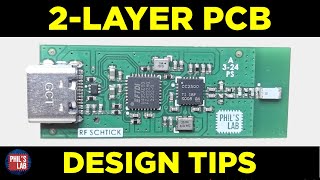
Aesthetic PCB Design Tips - Phil's Lab #84

Вставка
- Опубліковано 12 тра 2024
- Tips for creating aestheticly-pleasing PCB designs, which in turn also benefit functionality, manufacturability, and more. From grid sizes, placement, silkscreen, to edge shielding, and more - make sure to incorporate these tips into your next PCB designs! PCBs by PCBWay www.pcbway.com
[SUPPORT]
Free trial of Altium Designer: www.altium.com/yt/philslab
PCBs manufactured and assembled by PCBWay: www.pcbway.com
COUPON CODE: PCBWAY-PHILSLAB
Patreon: / phils94
Mixed-signal hardware design course: phils-lab-shop.fedevel.education
Advanced Hardware Design Course Survey
forms.gle/X4jwvtZeJ1jTXh7r9
[GIT]
github.com/pms67
[TIMESTAMPS]
00:00 Introduction
01:10 PCB Showcase
02:34 PCBWay (Coupon: PCBWAY-PHILSLAB)
03:14 Altium Designer Free Trial
03:39 Why Aesthetics Matter
04:51 Grids
06:22 Sectioning
07:37 Traces
09:35 Board Outline and Component Placement
10:43 Edge Plating/Shielding
11:49 Rounded Corners
12:35 Silkscreen
15:38 Surface Finish and Soldermask
17:26 Outro - Наука та технологія


In a previous job, we used mask color to specify rev or phase of the product. Development was red, confirmation prototypes were blue, and mass production were green for cost reasons. Made it very easy to see what version a board was
Ah yes, I believe I've heard of that being used before. Quite a cool method.
As a 35-yr+ veteran of EE, I can always tell the level of the designer by just looking at the bare PCB.
Except on white boards, I always put a rectangular box of silkscreen, to allow writing on with a fine permanent marker - useful to note issues while inspecting/ testing, numbering etc.
Also that white silkscreen could be used for layering a marking... in theory, since I've not actually done it.
Teardrops are also good for mechanical strength for larger parts, connectors etc. to avoid fracture of tracks where they meet the pad
Back when I did PCB layouts aesthetics were always important to me. It seemed that many engineers and other PCB layout people couldn't care less about the look, just get the layout done ASAP.
One engineer did complement me when he said "Wow, I can SEE the signal flow!"
Been designing pcb's for 20 years now.. My motto is that if it looks good, it will work good! 😊
I've always found that people think that something that looks good will also work well.
So if you're going to build a bad product, at least make it good looking.
16:49 Green Vs Black or other solder masks : the human eye is more sensitive to green and red colours making it easier to see the copper traces under green and red rather than black solder masks. This helps with debugging especially where traces are parallel with each other.
Great video thanks for sharing
Yeah, I love using inverted silkscreen for things that the end user wants to find. The user quickly learns to tune out the noise silkscreen, and just see the inverted, end-user things.
Yeah that. Top layer has TP1, TP2, etc. Bottom layer give a short description of what that test point is.
"Noise silkscreen" is a good way of putting it!
@@MegaKylef I'm tending to put assembly instructions on the silkscreen now. Instead of J1, J2 etc, I have the part number or wire colour, so the person assembling the board has a better indication of what goes where.
I think 0.5mm (or 0.25mm at a push/with smaller than 0402) placement grid should be a legal requirement for PCBs 😅 it makes boards sooo much nicer looking, quicker to arrange components (less options), easier to assemble… Easily the best board design tip I ever learned.
Thanks for making a video on this topic. The aesthetics bring me joy while designing, and that has to be worth atleast a teeny bit. :)
Thanks for watching :) I agree - it's actually one of my favourite thing about PCB design.
Phil has been knocking it out of the park the last few months. One fantastic video after another.
A tip: As Phil alludes, some of the aesthetic appearance tuning steps tend to come at the end of the pcb design steps. This is right when there's pressure to get the design files to the board house ASAP. To avoid forgetting one of these satisfying appearance steps, it's a good idea to maintain a checklist of items to perform at that stage. Both standard items, and any items that occured to you earlier for this specific board. And of course rerun the Design Rule Checks when done.
Another good looking thing is to use the gold plating as a font/indicator.
We usually don't use silkscreen, but often the customer wants some indicators, then I place a mask on the solder layer and the same on top to have a nice shiny looking indicator.
A man of quality 👌
Lots of good stuff here - thanks for sharing. My two penn'orth: I like to add silk screen rectangles and text around lower-level functional areas (e.g. regulators, filters, etc.) - I think of the person who might be repairing it in 20 years time...
I usually try and focus on adding as much symmetry as possible, if the deign allows for it. Most people seem to be drawn towards symmetric designs in general. Love the video as usual!
Exactly - there's something really satisfying about it.
Thanks for watching!
True, but symmetry can be a detriment to performance, so don't sacrifice performance for aesthetics.
This is very informative and well done. Thank you.😀
I started layout on circuit boards around 1979 on a light table, two sheets of frosted mylar, rolls of 40 thousandths tape and an xacto knife! For a hobby now I use Fusion360's integrated electronics module with the 3D CAD so I can make sure my boards fit into the enclosure. How far we've come!
Thank you for all your remarkable and fruitful videos Mr. Phil 🙏🏻🙏🏻🙏🏻
Thank you very much for watching! :)
Immidiately respect to UA-cam video ep creators that number their videos, makes it so mich easier to find useful ones. 👍
Phil, huge thank you for your videos, just thanks to you, and your videos, I started designing my own circuit and PCB. And just thanks to you I realized I can avoid soldering it by myself, and order complete assembly. Though my own designs are quite basic compared to your masterpieces, still I feel more confident with my habit.
Thanks a lot!
Thank you so much Phil. Great video!
What a great week, two videos in one week
This is one of the things I like about your boards, they look aesthetically pleasing.
Thanks, Khadem!
Great video
Great points in PCB design/fab.
Thanks for sharing your expirence with all of us 👍 😀
Thanks for watching, Asger!
very professional and helpful ,Thank you for sharing
Thanks for watching, Pham!
Let's just all accept that we love the beautiful PCBs since the childhood when we used break open old electronics to stare at these PCBs and we just absolutely love it when we get stare at the beauty of the PCB we freakong designed ourselves. We get to be the artist we used admired since childhood. And for that my friend, asthiestics is absolutely fucking worth it
Completely agree :)
PCB layout is like town planning. Where to put McDonalds... I hate seeing old PCBs in landfill or at the dump. They're so often works of art. Even your average motherboard is replete with care, inspiration and artistic flare - and somebody probably put their heart and soul into making it real. I have PCBs hanging on my wall (single sided naturally). Sad I know but it inspires me. Good job we have multi-coloured solder resist otherwise my bedroom would look like Kew Gardens!
Tks a lot for sharing your knowledge. Subscibed and liked all your videos.
Really. TKS A LOT
All the manufacturers I've ever used automatically punch the resist layer through silkscreen so you never get silk on pads.
I've never had an issue either (then again I never put silkscreen on exposed copper anyway) - however, it did come up in the IPC CID course, that some manufacturers will just not care and go ahead with it anyway.
I often spend way too much time making tracks look neat...
Tell me about it.. :D
Nice topic! I always make sure of the functional parts, but I treat them as art as well.
David Jones's PCB Design tutorial (i think I read a while ago on your recommendation) mentions only ever using thou/mils and metric only for manufacturing dimensions. I noticed you using metric. Wondered what you thought on this topic as someone brought up with metric.
On a different tangent: It depends what you are optimising for but I feel better to use fonts that are optimised for legibility at small sizes, typically newspaper fonts excel at this, century gothic is OK. Generally sans serif is a faux pas for small text when legibility is the priority. Counterpoint; Bell Centennial is a good example of a sans serif font optimised for density and poor printing used as small as 6pt, ideal for silk screen. Typically Egyptian style fonts excel. An equivalent Egyptian font like Lucida will be more legible than a san serif. Guardian Egyptian is a nice modern example of a font optimised for newspaper sized text. The grotesk style font used in most youtube thumbnails is often not great at peoples natural astigmatism leads to edges being blurred :)
This is content I like! Typography to the people!
Thanks for your videos🚀
Hey Phil, I have a request. It would be great to make a video on how to look for pcb design jobs. What could be the requirements or interview topics? etc.
I couldn't agree more with this and I believe any PCB designer will say they love the 'end bit' of tidying up ! and your right It gives you a bit of an artistic outlet like solder mask colours for instance. I like Matt black, as many do but I like anything Matt, my second choice would be green, I dislike red PCBs because a firm I worked for made all prototypes in red so they couldn't get out in the wild ! from then till now I consider red PCBs to be unfinished or simply wrong ( PCB prejudice ? Lol ! ) Regarding fonts only use one or two at the most as loads of different fonts look awful, apart from that it's about time we had a vid talking about this as it IS important...cheers.
Definitely is one of my favourite parts when it comes to PCB design. Matte green is nice as well, especially if the traces should be more visible.
Agree - I'm not much of a fan of red PCBs!
Awesome video !
Thanks!
Thank you for sharing
Thanks for watching, Arjan :)
I have never used Altium, but Kicad automatically takes care of most of the problems you mention. For example silkscreen on top of cover is automatically removed unless you specifically ask for it.
Great video, but regarding the grid size of not going smaller than 0.25mm how do you get the components to line up and the traces to enter the pad uniformly without making the grid smaller? Every time I use a 0.5 or 1mm grid I end up having to go smaller because it never looks quite right. Either the component isn’t lined up or the trace isn’t straight. I’m use Ki Cad 6 for my designs for reference btw.
Hi Phil, great video as always. I am a strong proponent of aesthetic PCB's. I do have a request to make a tutorial on routing in Altium. I find it very hard to route since Altium doesnt always allow me to place traces the way I want. It seems to fight me for it. And moving components after routing is a nightmare since the traces dont move with the component gracefully. Thanks
I have OCD, so this is very important to me
This is a really important aspect when designing prototypes for clients I've found. I work in the creative/event industry and the people I design for are very interested in aesthetics, even though as you say, nobody will see the tech in the actual product/event. Also, I recently made some business cards that can also play Tetris and hiding the vias under chips and between the LEDs in the 10x20 matrix - and even the routing of the tracks - was important (the card itself is only 1.6mm thick + the height of the LEDs, as the battery sits through the card - it all runs from a single ATMega328pb chip - and also shows other info and animations on the matrix depending on the mode its in :) ). Of course it helps that I'm VERY OCD when placing parts :)
I also tend to place parts that need to fit through a casing on cm boundaries when possible, as it makes it much more simple to measure and cut/drill casings accurately.
Nice lecture.
Thanks, John!
Thank you
Aesthetic is appreciated when sit and debug our designed boards, on commercial dev boards this is very much applicable.
For the ground edge of the board trick what’s the fastest way to do it? Did you just manually use lines and arcs or is there like a trick to do it quick?🙂
I am doing most of your recommendations not because I am a good engineer but because I have a form of OCD:))
Glad to hear you’re a fan of Century Gothic
Looks like that makes at least two of us! :)
My latest board had a big arrow on the bottom of it, with the lettering “this board is a skeleton, do not trust what it says”. Wonder what was below it in the shared panel?
I once built an ITX computer, and the tiny motherboard (Asus Z590-i) was so good looking, I just kept staring at it like a piece of art, before installing all the other components.
I do the same to be honest - something mesmerising about nice-looking boards.
I also like the aesthetic of rounded corners, and use that for all my PCBs, but I don't really see that PCB manufacturers can't mill sharp corners, as long as they are not internal sharp corners.
I think your boards would make great commercial success, I hope one day I can buy some.
Thanks, Vasile!
how do you make vias and pads have the same color as your layer?
Note that for scoring/snap options, rounded corners should be avoided. Panelization with these methods can dramatically reduce the cost in larger quantities.
Hi Phil. I often see stitched mounting holes which are also PTH. What are you thoughts? I just assume that the stitching is redundant unless it has to do with inner ground layers or better purchase with mounting hardware.
This is normally for PTHs that are Grounded. The plating for the mounting hole can be removed by the sharp thread of a screw, so adding vias provides a strong electrical connection even if this plating was damaged.
Its also to anker the copper, the twisting of the screw might rip of the pad otherwise
Can you show use how to lay out a complex board (8-12 layer etc) such that the tracks aren't crossing constantly. It's seems that you have the ability to layout without crossing at all. I hate how crossing looks.
I made the mistake of having the font size so small the power and ground marking couldn't be distinguished. Looked huge on the preview
I love your videos
Thank you, Neo!
Its so informative video , but I hv a question, for beginners pcb designers what kind of staff they need to study to be able to design
Most importantly something like electronics and schematics design. PCB design comes by the way or later.
Just checking, when you talk about silkscreen on copper around 13:20: you mean exposed copper right, and not that there is copper under the soldermask?
Yes, exposed copper or tented vias
I thought the same at first, but yeah, putting silkscreen over pads and vias.
I've been following for a while and this weekend I just managed to get my first full signal path through my code. Now I have no excuse but to try and learn to speak "Greek". I just get lost as soon as you start speaking in Mathematics. Literally as soon as I see a w (omega) I switch off. It's gibberish to me. Sometimes I can "see" what you are doing and understand what the code is doing, but I can't understand that in the language of Maths and I just don't speak it. I'm hoping to find a library and aid my learning by me only havng to figure out what I want and how to set it up.
If I may suggest one public project as a universal PLC with STM32 with CAN Ethernet Wifi with lot of IO for Home automation programming with ST Software
I add logos on the copper layer with enig finish, is this bad interms of functionality?
No, that's common in commercial pcb design. Only be careful, that you don't accidentally create some short circuit.
So long as your copper isn't connected to anything. It can looks really good!
Aesthetics are primary indicators of if something is going to work, work well, and be maintainable.
If the producer can't make it look good, they probably struggled in other areas.
How did you get the yellow colored silkscreen? There’s only black and white to choose on their site 🤔.
PCBWay offers it when you choose their 'Advanced PCB' service.
@@PhilsLab oh nice, and there are even more fancy colors (and other stuff I don’t have a clue of 😅).
Hi, I'm a beginner, I have a question, if you are working full time for a company and making a PCB for them, they are the product owners, so should I sign the PCB with my name or just put the company logo and version number?
Only the company data
where can i download this PCB file
Can we talk about Smile Wang from Pcbway lol
square corners should be fine with vscoring
❤
I see you removed all your designators, don't you think it would be more easy to have them at a lower font size and do add them?
As also stated in the video - you shouldn't go below 1mm character height if you care about readability. Then try and pack component designators on silkscreen on a tightly-packed board - pretty much impossible. In addition - what does adding designators help, given a properly done assembly drawing?
👍👍
Tenting vías is not recommended because some acid may remain inside and destroy the copper.
I end up needing my pcbs to be as small as possible, and to use only components I have on hand, and I hand solder everything. All my pcbs are ~20mm2, asymmetric and ugly as hell! ;D
I picked up on a trend of putting totally useless information on boards silkscreen. For example: "WARNING: FOR EXTERNAL USE ONLY" or "NOT TESTED ON ANIMALS "
Might need to try that out on the next board :D
@@PhilsLab My latest board 'graffiti'
i.imgur.com/CSlPMCN.png
👍🙏❤
I would actually buy an aesthetic PCB (preferably populated) as art - if I come across one...
No designators in your silkscreen?
Phil puts them on some boards and not on others. Having had to troubleshot so many boards that don't have component designators, I am very impatient with that practice.
Depends on how cramped the board is and what revision it is. If it's a prototype, sure - I'll try to put on designators, but for production runs or the like where everything has been tested, there is no need. A suitable assembly drawing will contain all the information you need in any case.
So you can easily turn them back on? Or is it an entirely new iteration? Wondering if EMS likes this approach. Looks very clean though.
Those mounting holes rub me the wrong way - annular rings are berely there, that machining around them is wtf.
It basically is proof-of-work for humans.
I'm beginning to think that Phil has an OCD when it comes to PCB design hence why he's so meticulous. This topic is not widely talked about in the technical space. After all, PCB design is not only purely engineering but also art.
A "pretty" low pass filter I made for a USB sound card based on a TI reference design ($$): i.imgur.com/0COBwae.jpg