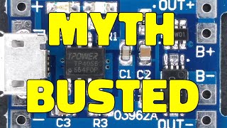
Increase charging current TP4056

Вставка
- Опубліковано 6 бер 2022
- 👉 ADS5012H : www.banggood.com/custlink/GGD...
👉 DT71 Mini : www.banggood.com/custlink/GmD...
👉 RD6018W : bit.ly/3oMozQe
👉 Super Bargain Day bit.ly/3v4cYzX
👉 Electronics Sale bit.ly/3u3a0KQ
TP4056 is a very cheap battery charger module, you can buy 4pcs for 1$. However, the charging current is only 1A. Today I will show you how to increase its charging current, very simple, just add a mosfet. The mosfet is controlled by pin 7 of the TC4056.
If you like my video, give me a cup coffee. Thank you very much.
Donate : www.paypal.com/paypalme/phdhung
Facebook group : bit.ly/CreativeElectronic
Contact: Magnetron0989821611@gmail.com
Phone: 0989821611
#Inverter
#Charging
#TP4056 - Наука та технологія


As the circuit change, it looks to escape TP4056's monitor and protection and use the P MOS charging always. It does not so recommend because it may burn out the battery.
de hecho a mi me prendio fuego la bateria Xd
who cares? Hype is must.
Adding an P-ch MOSFET in this way will no longer limit the output voltage to a safe level. Any kind of undesirable result can occur.
çıkışa zener diyot ekleyebilirisiniz. ayarlı olan tl431 olan bu işi görecektir diye düşünüyorum.
TP4056에 대한 영상을 잘봤습니다. 아주 좋은 영상인듯 합니다. 저도 따라 해보고 싶어 집니다. Good job 🥰😍🤩🥰😍🤩
Hey bro u can add a suitable resistor between vcc and charg pin as when the bat reaches the cut off voltage the gate of your mosfet will be floated so by adding the resistor u grantee that the mosfet will be off
Maybe there is resitor on board
I'm pretty sure the pin on the board is already driving an onboard FET. This is adding an extra Fet in parallel to that.
@@robmc3338 There is no external power mosfet.
@@robmc3338 😂so is it practical to do this reply
Can you modify the board to change the cut off voltage? It seems like the TP4056 I have don't cut off charging until closer to 4.31V-4.35V which I'm sure will trash the batteries in short time.
Can you do something similar with a stepper driver to drive bigger (higher current) motors? For example an open source driver like this one MKS SERVO42C or SERVO57B ???
Even if the current is evenly distributed across each battery, it makes 2.5 amps per battery, which can be dangerous. Especially since the structure of the batteries cannot be equal, some batteries are much more dangerous because they will normally charge faster. In my opinion, it is a circuit design that is not recommended.
I agree with You. This kind of batteries are really dangerous when You Charge them with higher currents than the nominal.
@@jjcreacionessoluciones Definitely a very dangerous video. Not everyone is as knowledgeable as we are.
I guess it makes whatever amps it gets, as the FET works in a switch mode :)
.
among other things, it is not certain that the current is distributed uniformly in all 4 cells, some could absorb more, some less increasing the risk of overheating.
Eu quero ligar um tp 4056 para carregar 9 células, será que carrega? Pra mim não importa se vai demorar a carregar, carga lenta acho até bom
Is it possible to increase MT3608 booster module ampere with MOSFET in this rule?
If so, please make a video of it.
We will test the maximum amperes of phone chargers with this TP4056 + mosfet, which is important in the power supply that will give 5 volts 10 amps. The application is very good, thank you.
No one else gonna mention about the 9 amp current on that thin wire? Im surprised it did not melt the insulation 😅
Is it possible to increase the amp of lm2596 by any MOSFET or transistor? just like Lm317🙂
The idea is very exciting .. but we need values of mosfet and resistance to give 3A or 4 .. that will be enough..
9amps is a very high current
Error, fake video, cant do it, it will burn
Top muito bom serve para vários projetos
It worked flawlessly thanks a lot
Hello,
Useful msg..
Hello brother, can i use this for 12v 10ah battery for battery chager??
Насколько я понимаю, транзистор работает в ключевом режиме. То есть регуляции заряда по току нет . Ток огранивает сам источник питания на 5 вольт . Решение не вариант.
Thanks for watching
окончание заряда контролирует микруха, по напряжению на банках.
@@user-oy8kd4ux5q да, но CC/CV тут явно не работает. Вернее, работает только ограничение по верхнему напряжению. Но там должны быть всякие trickle charge режимы и т.д. Будут ли они корректно работать или нет неизвестно.
@@wirtdonners4212 известно. не будут.
Тут показан вообще "апгрейд" для идиотов желающих спалить свой дом.
Здесь просто вставили ключ (транзистор) который тупо напрямую подключает АКБ к источнику питания. И разомкнётся только при достижении на батарее 4.2 В.
Токоограничения кроме сопротивления проводов нет (если его нету у БП)....
Да лучше тогда просто плату защиты поставить и так же напрямую к источнику подключаться.
Автор этого "улучшения" либо идиот, либо вредитель
@@user-jd6yf9yl6g Согласен, так себе идея.
Зарядный ток большой величины сокращает срок службы аккумуляторов. Зарядный ток должен быть не более 0.1А на 1А АКБ. То-есть, если АКБ 40А, то его максимальный ток зарядки 4А.
при такой схеме контроль тока зарядки вообще отсутствует.
Заблуждение. Зарядный ток литийных элементов может быть в половину от емкости батареи. Не путайте со свинцовыми.
Good idea but be careful your power source for charging must have “ CC “ mode “ current regulations” , high current damge the battery and dangerous must calculate how much current need for safe and good charging.
Wow nice post.. easy and simple. thank you very much
You should always monitor battery cell's temperature while charging with more than 1C (one-C) current.
As well as the temperature of the external field effect transistor. After all, the power on it will stand out considerable./ Равно как и температуру внешнего полевого транзистора. Ведь мощность на нём выделяться будет немалая.
hi, what is 1C mean?
@@ClassyJohn It means the Capacity of the battery. Example a 1000mah battery which is 1A battery can not be safely charged at 1A and it could cause damage to the battery or even make it explode. The typical safe recommendation is 0.5C which is half the capacity of the battery, so 500mah charge rate in this example.
@@Angryhelder What if a battery is charged with less than 0.5C, like 0.2, will it damage the battery?
@@naingtheawperc3817 preferably you want 0.5c or less so that is fine.
The circuit is interesting but don't take in consideration the real charging current per cell. Exist the risk of battery explosion due a excesive charging current. The TP4056 is design to supply 4.2 volts and 1 amp per 18650 battery. Please take in consideration the battery specifications before make risky circuits.
Can i use this for 3.6v battery?
Bro do module ko aapas me jodne par ampere badegi ya nahi. 1 module is 1 ampere max, jab ki Mera phone 2 amp tak support karta hai. Ek module se slow charge hoti hai . 2 module se fast charging hogi ? 🤔
sir my question is you are using which power supply for 220v AC to 5v DC supply i want to sea can you edit pictur in this video for refrence
how about if the input is 3A? it make a 3A output right??
Does the clamp meter only measure ac current?
I couldn't understand the working? How does the IC change from CC mode to CV mode? Your modified circuit always charges in the battery in CV mode.
bagai mana untuk pengisian baterai 18650 8 pcs mengisi cepat dalam satu module dapt megisi 10 jam untuk pembuatan lampu tenaga surya(energy solar cell) saya mencari modul itu
Is it possible to modify this module for AGM 6V 4.5Ah battery control?
So you are using the exit to the charging led (pin7) to trigger the mosfet ? You should inform viewers that they can't use an 5V 50A power supply to do this ...
Expose fake | Increase charging current TP4056
ua-cam.com/video/NtVNHI0mdtE/v-deo.html
Just connect that heavy gauge wire from the + of the input to the + of the output. 20amps instead of 10 amps.
yüksek amperin tehlikeli olacağı düşünülüyorsa 10 veya 20 adet pil için kullanıabilir yani 20 pili aynı anda şarj edebilmek için güzel
Can i use this to charge 12v battery?
Good battery can charge 1C or 2C but a lot battery with no brand very dangerous if charging 1C or more. I like your idea for increase ampere but better you give a note for new people in electronics. Btw how to increase charger if i just want 3A, 5V? Can you making video for me? Thank you
Hello, greetings, thanks for your tutorials that are very interesting, I want to ask you, how many 18650 batteries in parallel can the TP4056 module charge.
well i just tried 4 and seen smoking coming from it so its not 4 haha
A very simple though great solution to increase the current! Thanks for sharing it!
Are you sure it's great?
@@tuxede I don't think it's working, however i give it a try. When it work, the energy problem is solved :-)
@@richardnoordhoff4288 it isn't creating more energy, it just allows more current flow. that is possible, and for that this will work, however the schematic also showed a protection diode which is missing here, as well as you need to be sure it won't remove the protection functions of the cirquit.
more curent(certainly)
does it still protect the batteries(Perhaps, it does to a certain extend, but should still test it anyway).
I can use npn transistor?
Look at 3:36 on the DMM and think about where the current limit is here 😉
Does the shutdown still work reliably?
?
@@plutonianfairy Look at 4:22 - the input voltage is passed directly to the battery via the IRF9540. There is no current or voltage limit in the circuit. What should be the maximum charging voltage of a 18650 cell?
Can I take IRF Z44??
Reply must
if you add a circuit like that. IC TP4056 which has been designed by the factory will not be useful. This is the same as charging directly with the PSU
Expose fake | Increase charging current TP4056
ua-cam.com/video/NtVNHI0mdtE/v-deo.html
Wow amazing beautiful idea 👌✌️ thanks my friend 👍👍👍👍👍👍
Why you use N-channel MOSFET and current goes via body diode
What was the board and mosphet please
Ciao mi sono appena iscritto e ho visto il tuo bel video per aumentare la corrente di carica con il modulo TP4056. Noto che tu hai usato un modulo micro USB, io invece ho dei moduli tipo C i collegamenti sono gli stessi? Grazie per la risposta
A proposito ne approfitto per un'altra informazione questi moduli che ti ho menzionato non mi caricano più di 4,14V/4,15V dici che può dipendere dalla corrente che erogano? Quindi con la modifica da te provata dovrebbero aggiustarsi? Ovviamente tu avrai usato un alimentatore da banco che possa dare i 10A.
Show the out put voltage and completion of fuly charge of the Battery pack
Because of MOSFET the out put voltage will be 5v not 4.2v for fully charge voltage of the 18650 🔋 battery
Expose fake | Increase charging current TP4056
ua-cam.com/video/NtVNHI0mdtE/v-deo.html
Bro how to increase the power of xl4016?.
좋은 아이디어 감사합니다.
Woww. Tutorial yang mengagumkan. Thanks you....
Expose fake | Increase charging current TP4056
ua-cam.com/video/NtVNHI0mdtE/v-deo.html
IRF9540 gate voltage required 10v miximium how this possible that the gates of MOSFET are open and crossing 9 amp and 4.2 volts.
Very interesting your video. TP4056 has a current limit of 1A, I ask you, how do you limit the current? Where do the 9A come from? Who controls this new current? If I put a 5V 30A power supply, what would happen? Thank you very much and a big greeting from Argentina.
He bypass the IC with Z44 MOSFET
At 1:34 you can see on the pinout of the TP4056 that pin 2 connects through R-PROG to ground. This resistor's value tells the chip which output current to use - so it has "programmable" output, up to 1000mA. The pre-installed resistor will be chosen to provide this maximum rating.
With this hack, this circuit (output current regulation) as well as the circuit for voltage regulation are bypassed. So, you are feeding whatever voltage and current capacity your power supply provides directly into the battery. To answer your question, then, it is the internal resistance of the battery that dictates the current draw, up to the maximum rating of your power supply - 30A in your case. The battery's resistance would certainly limit the current to something less than that, but it would very likely be too much current for safety.
Therefore, the only function then that TP4056 is now providing is the charge termination, which is supposed to cut off the charging circuit when the current draw reaches C/10 ...typically this is around 100mA. It is unlikely that the TP4056 will provide this function at these higher voltages and current. So, if you're thinking of doing this hack you might as well just connect your battery directly to your 5V source!
Còn hiểu chỉnh được không bác chứ em thấy 2.25A với 4.4v hơi to nhỉ
Very helpful bro 👍
thank đã hướng dẫn phá pin cho nhanh hỏng cách này rất hay.
The way you increased the charging current is great, but remember you need to connect to a charge ballancer. I only know there are series connection ballancers, so I'm wondering what to do with a parallel charge. If anyone knows about this pls comment.
En estos casos, no necesitas un balanceador extra.
Схема хорошая, думаю ни кто больше 1,5-2 А заряжать не будет
схема плохая! транзистор не может регулировать ток и это не минуемая гибель акб или вовсе взрыв...
Это схема хороша если ты пожар хочешь устроить.
В этой схеме отсутствует ограничение тока. Вернее оно есть но только лишь из-за сопротивления проводов и мощности БП.
Просто поставь плату защиты на АКБ и подключи напрямую к БП и будет тоже самое, даже лучше, потому как у платы защиты есть хотя бы защита по току.
Which transisret no. And resistance value
excellent video friend to load the pack faster. I was wondering when you upload the video of the double EE55 5kw source. for the investor.
Expose fake | Increase charging current TP4056
ua-cam.com/video/NtVNHI0mdtE/v-deo.html
How you manage the overheating of tp?😱
As per spec, the 4056 outputs 4.2V on the charging circuit. Won't this hack increase the charge voltage to 5V (or whatever the input voltage is) thus risking overcharge damage to the cells as they reach capacity??
I think the original charge board will turn off the mosfet when the battery reaches 4.2V via the pin with the 10 ohm resistor he added.
Cables will need to increase to handle increased current, also the chips won't be able to run this continuesly only for short burst of time and then you have no safety mechanisms like reverse/return voltage build in that design
Який мосфет і резистор потрібно припаяти, щоб отримати 5А струму зарядки для 3 акумуляторів 18650. І для 3А струму зарядки для 2 акумуляторів 18650. Працює такий принцип на платах із захистом?
це фейк
I have two questions.
1) With this change, does the circuit continue to turn off current after the battery is charged?
2) I need a current of 2 A. Is this circuit suitable?
I would be grateful for an answer.
just add 2 modules on top of another in parallel, you will get 2A
@@JawadAhmadsahibzada I connected two TP4056E modules in parallel: for some reason, the output current did not change. On one of the boards, two diodes are lit at the same time.
@@sddfefr5686 I used 4 tp4056 in parallel to charge my power bank quickly. I tested around 3.8A going to power bank. But make sure you’re using 5v 2A charger minimum for 2 in parallel
Nice video, thanks, like it :)
Thanks, an amazing upgrade.
Can you explain me how calculate resistor to modify the charge current?
See you next
The maximum charging current is limited by the power supply itself. The gate resistor does not affect the charging current.
hello, good work, input 3.7 volts, 5 volts, 3 amps, can you make a circuit with an example mosfet
Thanks for watching
If it is a N channel mosfet, how to connect it?
Good job bro 👏👏👏
It's quite simple but really good to see! I wish there were more people like you!
Just make sure you solder it better, and rather solder a wire to the board than the resistor directly. You really do not want a short, don't mess up with lithium batteries!
Yes, this is just a test.
@@PhdHung I understand. Just telling other people.
Also, this mosfet has a little bit high Rdson for 10A. Check out the IRF5305
I think banks should be charged to the minimum of 10% of their storage capacity, for example if I have a 100Amp bank I must charge it to 10 Ah, so as not to increase the internal resistance every time I loaded it, the idea is great only that that mini battery bank is too small to load it that way. If you want to charge so fast, better use Ultra LTO Capacitors
@@rickhuntraslam2925 what you mean is you want to never discharge below 10%... there is already a security threshold. We do no discharge Li-Ion or Li-Po under 3V per cell, yet each cell could get down to about 2.5V before any real damage happens!
Also a 100A bank doesn't mean anything, it's 100Ah!
A are used to measure a current flow!
Ah are used to measure a capacity, it's how much A you need to draw to drain the battery in an hour!
That is a very common mistake I have even seen on official products like more or less famous bluetooth speakers!
@@Zebra_Paw ok
Wow man , you can do anything , it's a super useful project for me atleast...
But how much input we have to give , 5V 1A or 5V 2A charger is sufficient?
5V 2A is almost too much. By wiring the MosFET via the LED charge indicator, it gets an enormous current gain. Combined with the low resistance value and the polished, highly efficient copper antenna, it can convert the missing power from the magic around it.
Sorry for the joke, but output power can never be greater than input power. If you want 5V 10A at the output you have to provide at least 5V 10A at the input.
Woww mantaap bung.. Tanks.. Vidio nya ya
How can I change the charge current?
i think that mosfet is a bit over kill for that small pack of 18650 maybe add some resistance for the a to lower it to 7 or 6 so the battery can adjust to its load since theres no balancer to balance them
How do you balance batteries connected in parallel?
It doesn't need a resistor, the current regulation depends on the connected power supply.
@@wernerpeter9706 just skipped on some part lol but you can do balance the batteries using a resitor to lower the output from source or like you said just change the supply to 4v 2a
@@tossancuyota7848 That's not balancing, that's charge control. In a parallel circuit, there are no voltage differences between the individual cells that need to be balanced. If you set 4.2V and 2A on the laboratory power supply, why do you need a modified TA4056 module? In this case, 2 cables are enough ;-)
So this modification is not only dangerous but also pointless.
Expose fake | Increase charging current TP4056
ua-cam.com/video/NtVNHI0mdtE/v-deo.html
What's the temperature like on the mosfet ? No risk of overheating ?
~40*C
Somewhat 2V at 10A, "40C" is only if you live on a pole lol. Well, unless (and I guess that is exactly what happens) he overloaded the power supply so it is what defines the current, not the useless charger.
Expose fake | Increase charging current TP4056
ua-cam.com/video/NtVNHI0mdtE/v-deo.html
привет. ну а под нагрузкой можно проверить? подключить что нибудь?;)
это же только для зарядки
It s good cranking up the possible current flow but there is drawback which is the cut off current of C/10 requirement of the lithium battery. Even though you max the power to 10A and attach 10 ish amp/h battery, the charging will stop at 100ma or C/100 which is 10 times overcharge. Not sure about if the batteries explode in the short run though
Bu uygulama sakıncalı mı telefon şarj adaptorlerinin makisimum verebileceği akımı görüyorum kaliteyi öğrenmiş oluyorum 4 pil lityum paralel bağlı 10 - 12 ampere bu şekilde elimdeki kaynağında tabi 10 amper çıkış vermesi gerekiyor
@@burakerisen3979 Lityum şarj işlemi pilin kapasitesi bilerek bilinmiyorsa tespit edildikten sonra sabit volt sabit akım (cc-cv) yöntemi ile yapılır. Lityum piller kapasitesinden fazla şarj olmaya dirençli değildir, piller şarjını tamamladıktan sonra eğer kontrollü bir şekilde şarj işlemi sonlandırılmazsa iyi ihtimalle yıpranak ömründen ve kapasitesinden kayba uğrarlar, kötü ihtimalde ise ısınıp alev saçarak patlayabilir ki bu telefon şarj ederken isteyeceğiniz en son şey olur. Videoda kullanılan mosfet sabit şarj akımını artıracaktır ancak şarjın sonlanması gereken noktayı tp4056 entegresi yine kendi üzerinden geçen akım miktarı ile kontrol edeceği için piller aşırı şarj olabilir. Özet olarak sağlıklı bir çözüm değildir.
@@burakerisen3979 Telefon adaptörlerinin max akım değerini ölçmek için bir direnç kullanabilirsiniz. değerleri 5V, 2A olan bir adaptörü V=I*R, 5v/2A --> 2,5R direnç kullanarak ve direncin iki ucundaki volt farkını ölçerek üzerinden geçen akımı okuyabilirsiniz. dirençin iki ucundaki voltu dirençin değerine bölerseniz üzerinden geçen akım değerini bulursunuz. örneğin 1,8v / 2,5R = 0,72 A
Çok teşekkür ederim bilgiler icin
Good night sir
Your music are superb
Нету не какого ограничения по току, думаю можно спалить блок питания.
There is no current limit, I think you can burn the power supply.
True, but if you keep in mind that there will be 9,1A charging current you have to choose a ≥10A power supply.
за блок питания не переживай переживать надо за акб ,транзистор не может регулировать ток и это не минуемая гибель акб или вовсе взрыв...
Good and nice to add ampere
Expose fake | Increase charging current TP4056
ua-cam.com/video/NtVNHI0mdtE/v-deo.html
My dear, I came to implement the circuit on 4056, I have a different shape, can you tell me what to do and thank you
Expose fake | Increase charging current TP4056
ua-cam.com/video/NtVNHI0mdtE/v-deo.html
Thanks y for video is nice.
Harus cas menggunakan charger hp sja ya, atau bisa langsung di sambang dngn charger laptop atau langsung di colok ke kabel PLN.
Mohon Solusinya .!!!
Sy SDH rakit baterai lipo4 dg voltase 12V.
Pakai trafo jika ingin langsung sambung ke listrik pln
dari trafo kamu harus ubah dlu tegangan trafo menjadi dc
Anda about the voltage on battery during the charge?
voltage gradually increase to 4.2V, then it will cut off charging.
awesome ideas and easy to understand with steps, by the way, is it safe for the battery?
Hi,
How many watts is the resistance for 10 ohm? Please
And it can charge an iPhone?
1/4W bro.
@@PhdHung
Ok thank you bro 👍🏻
And if not, can it charge an iPhone?
How do I change the charging current to 200mah? 🤔
oh thx, i was looking for this, i was thinking how to drive a power mosfet on it and you got me on the led indicator, that's very clever to use it to cut the mosfet.
Bravo 👏👏👏
Awesome explosion
Very good!
Thanks bro
Супер братан! Спасибо за видео!
@Andrey Orel чтобы зарядить с большим током
@Andrey Orel разогнал модуль зарядки с 1 до 9А по току, для того чтобы параллельные сборки не заряжались вечность
@@Deemon1
А как теперь модуль понимает какое напряжение на акуме?
@@alexandr_84 , аккумулятор подключен штатным образом к плате зарядки. Плата контролирует напряжение и отключит зарядку когда нужно. Данный товарищ применил лайфхак. Управление дополнительным транзистором зацепил к ноге 7 контроллера - лампочка окончания зарядки. Загорается светодиод, мощный транзистор отключается. Колхоз во всей красе.
@@alexdubovik2119 я уверин на 99% что так только убьёшь акб силшком большой ток и тд.
whats wrong with u guys haters... he only show u it is possible to increase the current. its up to u to do it or not. and it easy to regulate the current.
Very Good...!!!
Có khi nào mosfet kích mở điện 5V từ nguồn vào ra đầu out luôn ko ad ! Mở vậy thì kích chạy 5V trưc tiếp qua luôn pin à !
khi nào đèn báo sạc sáng thì nó mới kích mở mosfet nhé
@@PhdHung nhưng khi mở mosfet thì nó cũng là mở ra out là 5V đúng ko ad ! Khi đèn báo đầy thì nó cũng ngắt mosfet ! Vậy thì chỉ là mượn mạch báo đầy để ngắt thôi đúng không ?
Expose fake | Increase charging current TP4056 #awesometech
ua-cam.com/video/NtVNHI0mdtE/v-deo.html
I am wondering why that TP4060 is not blown up at 9 amp without any cooling. Even at 1 am it gets pretty hot.
Not sure this video is fake or real.
Unfortunately, it's real. The TP4056 is still only supplying 1A (and has internal current limiting for over-temperature anyway). But the circuit is using the "charge" indicator output to turn on an external MOSFET between the supply and the battery and that is supplying the extra 8A. The IRF9540 has a resistance of around 0.2 ohms when turned on fully, so the current is being limited crudely by whatever the power supply is capable of. Not a safe circuit.
HOW about temp?
Hay mejores opciones con otros módulos como el MRB045 y no tener que andar modificando el TP4056 pudiendo llegar a un mal funcionamiento.
Drain pin should be isolated, not connected to module negative output. Module will damage if it gets more current at output.