For people who are still confused, here are what you should know: If there is no current flow, resister will not consume energy/voltage, therefore no voltage drop across resistor. Think of current as it was water flow, voltage is the pushing force to the water, if 1:there is current flow, resistor will "resist" current flow such that there is a voltage drop across resistor according to Ohm's Law, thats the resistor will "push back" the driving force(voltage) such that it matches the driving force of the other end of the resistor, thus voltage drop will be 5V. if 2: there is no current flow, resistor do not consume energy/voltage because V=IR I=0 V=0, in terms of water, there is no water flow, but the driving force is still here and still "pushing" although there is no water flow, thus voltage will not drop if there is no current.
It’s an ideal diode so it can essentially be replaced by a short as long as it is forward biased which it is. Thinking of it as a short means any voltage drop would not make sense.
Shouldn’t there be a voltage drop across the diodes in e and f. So shouldn’t it be 2.3 in e be a of the 0.7v voltage drop across that diode and likewise for f.
So in ideal diodes, they can be ON whenever they have a zero or more voltage at their anode? meaning they don't need to have a forward bias voltage of 0.7 V?
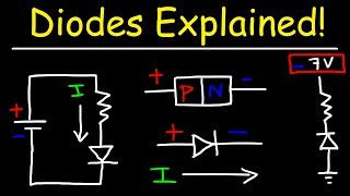
You are right, the way it is drawn is 5 volts. However, if we accept that the anode terminal has a -5 voltage applied to it, the diode is then operating in reverse bias, or operated in the reverse direction. This occurs when you apply a negative voltage to the anode(+) of the diode. He should re-draw the diode to be in the reverse bias orientation since a negative voltage is being applied to the anode, that is flip the diode 180 degrees. This would then agree with the instructors answer choice. Microelectronic circuits, Sedra Smith, 6th edition, P 166 section 4.1.1 .
I assume you are referring to the circuits "e" and "f" examples. They aren't connected in parallel electrically. Parallel means they have the same voltage across them. These don't. Each diode is connected to a different voltage. Only one of the diodes will conduct. The other diodes will have a different reverse biased voltage that does satisfy Kirchoff's Voltage Law. In example "e", only the diode connected on the left to 3 V will conduct. This makes the output voltage also 3 Volts (assuming ideal diode model). This voltage keeps the other two diodes reverse biased and "off". The diode connected to 2 Volts will have a 1 Volt reverse bias. The diode connected to 1 Volt will have a 2 Volt reverse bias.


Great explanation on the way diodes conduct. Very clear and gets to the point. Great job!
For people who are still confused, here are what you should know:
If there is no current flow, resister will not consume energy/voltage, therefore no voltage drop across resistor.
Think of current as it was water flow, voltage is the pushing force to the water,
if 1:there is current flow, resistor will "resist" current flow such that there is a voltage drop across resistor according to Ohm's Law, thats the resistor will "push back" the driving force(voltage) such that it matches the driving force of the other end of the resistor, thus voltage drop will be 5V.
if 2: there is no current flow, resistor do not consume energy/voltage because V=IR I=0 V=0, in terms of water, there is no water flow, but the driving force is still here and still "pushing" although there is no water flow, thus voltage will not drop if there is no current.
Shouldn't it be 0-(-5)=5V in c)?
Ya the answers of my book is -5v
part c is +5 V...The way V is labelled, it is the voltage across the diode, not the node voltage
yes i was thinking the same thing.
Thanks for the help, understood how diodes works in less than 10 minutes
wow. thank you so much. very helpful, straight to the point and easy explanation.
This course is perfect,thanks sir :)
Thank you sir.
Very helpful and straight to the point
What videos should I see, in order to fully understand this tutorial
Salt Lake Community College ... my Alma Matter for my generals and EE first courses before transfering to the U !!
I Still don't get it :(
excuse me , but i don't get why only one diode can be conducting in the 3 diodes problem ..
can u repeat it ?
謝謝老師的講解❤
really helpful prior to my quiz!
Why is there NO Voltage Drop across that Diode in A?
It’s an ideal diode so it can essentially be replaced by a short as long as it is forward biased which it is. Thinking of it as a short means any voltage drop would not make sense.
In problem (e) 1v will conduct because time taken for f/b is least one. So my point of 1v conduct is that right.
In real life situation the (a) Vo should be 0,7V - not 0V. Right?
Great video! Really helped
Thanks 👍😍😊
Amazing
Shouldn’t there be a voltage drop across the diodes in e and f. So shouldn’t it be 2.3 in e be a of the 0.7v voltage drop across that diode and likewise for f.
he is talking about Ideal Diodes so 0V, I believe you are referring to Practical Diodes, which makes you statement correct.
So in ideal diodes, they can be ON whenever they have a zero or more voltage at their anode? meaning they don't need to have a forward bias voltage of 0.7 V?
If you are still wondering a year later, that is correct lol
perfect
Thank you sir.
on Part D why is the voltage 0
Because its an ideal diode and voltage drop across ideal diode is zero and v is voltage across ideal diode hence v=0
@@regale5359 so if it a practical diode will the V still 0 ?
thank you sir
Hi, Please take 0.7 V into consideration to turn on the Diode.
He's talking about ideal diodes, so 0V drop. The standard 0.7V comes from an assumption of non ideal diodes
wonderful :D ur explaination's very clear :D
part c should be positive 5 volts
+Uzair Warraich incorrect, there is no way it can be +5 volts because the source is going from -5 V to ground.
+wjs no, because there is not voltage drop across the resistor, so it is pulled to 5 volts
The anode is at -5V and cathode at 0V. V is the cathode to anode voltage = 0-(-5V) = 5V!!!!
You are right, the way it is drawn is 5 volts. However, if we accept that the anode terminal has a -5 voltage applied to it, the diode is then operating in reverse bias, or operated in the reverse direction. This occurs when you apply a negative voltage to the anode(+) of the diode. He should re-draw the diode to be in the reverse bias orientation since a negative voltage is being applied to the anode, that is flip the diode 180 degrees. This would then agree with the instructors answer choice. Microelectronic circuits, Sedra Smith, 6th edition, P 166 section 4.1.1 .
toledo me va a clavar
furthermore, they cannot be different voltages in parallel it is a violation of kirchhoff laws, how did you dare make examples with different voltages
what wrong with it? we did a lab with the same circuit, where there are different voltages in parallel.
I assume you are referring to the circuits "e" and "f" examples. They aren't connected in parallel electrically. Parallel means they have the same voltage across them. These don't. Each diode is connected to a different voltage. Only one of the diodes will conduct. The other diodes will have a different reverse biased voltage that does satisfy Kirchoff's Voltage Law. In example "e", only the diode connected on the left to 3 V will conduct. This makes the output voltage also 3 Volts (assuming ideal diode model). This voltage keeps the other two diodes reverse biased and "off". The diode connected to 2 Volts will have a 1 Volt reverse bias. The diode connected to 1 Volt will have a 2 Volt reverse bias.