As an electronics enthusiasts i find your videos to be very informative and amazing. Such knowledge can only be gained through experience and im glad you share this with everyone. Thank you.
Although many changes were needed, this video is educational by showing the approach and considerations to upgrade the power output of switching power supplies. Great video!
Thank you for sharing this information with us and your experience. I have read most of the comments from your followers and I tell you, that is very impressive. I am an electronics enthusiast and have very little experience learned much from it and will share the video. From the Dominican Republic Guillermo keep it up.
Good video. As they say, the parts to make it costs pennies (usually), the knowledge to make it is priceless. In my case just finding the magnet wire to rewind the xfmr would cost many times simply replacing the ps with a bigger/better one but where would the knowledge come from? However, the safety concerns expressed in the comments are valid. Opening up and modifying any mains level electronic device is dangerous so don't do this unless you know and understand the risks. The shock you receive could be deadly!
Regards , Kasyan. Excellent channel. As your colleague , if you dont mind, i would add one precaution and warning - safety margins when winding SMPS transformer. In your video , i saw that you haven't left any space from end of winding to the end of transformer body. If you look closely , industrially made transformers have winding that is in wound in the middle of body ad have some space between ends. Sometimes they also use some insulating "sleeves" for ends of wire that connects to the transformer pins. That ensures better primary to secondary insulation and that can be dangerous from the safety point of view. Everything else is excellent , thank you for detail explanation , i really enjoy watching your videos. Keep up the good work.
All your videos show your expertise on electronics and very valuable advise. Very clear videos and with diagrams. I think i will finally decide to try your template files so I could try Jlcpcb boards.
Good day. Is it also pssible to step down a 19volt laptop power brick to output 12volts just by modifying the windings. Without using any extra components such as a regulator.
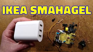
the casing looked identical to one I already have but the inside is completely different, I changed the voltage by changing the feedback resistor but I still need to make some tests
Can you find about small 6 pin smd chip in most of latest power supply, their is no information about that chip numbers on internet. Your video was just amazing and fabulous 👍👍👍👍
Just double the amount of turns on the autput and change the voltage of your Z diode to 22.8 v and make sure that the components on the output can handle the voltage. Im not sure but I think it is right.
It is possible to built or adapt this transformer circuits in a way that if nothing is connected as a Load, the whole circuit works as an open circuit for input stage??.. i mean, that if nothing is connected and the transformer still plugged, it stay there with zero power consumption
The idea is learning and the satisfaction you get from being able to do something like this... that guy was right you missed the point of the video....
Regularly i watch your channel. Please also explain which pins and layer of transformer corresponds to primary windings 1& 2 annd secondary winding 3 as per your circuit. It is confusing actually which winding is enhanced by you. Thanks.
Nice video but i have a question about 5 v dc android wall charger of 40 amps with switching FET 10N60 operated with a smd ic. Due to the fluctuation main input Ac 220 volts switching FET Transistor is burnt along with frequency controlled smd ic not available generally. Can i replace this burnt switching part of the circuit with other part of the circuit board ?
Very interesting in principle! In practice however, a 2A 5V charger replacement could be purchased for less money than the time (=money) it would take to make this modification. Great knowledge for enthusiasts and engineers, though! Using the same principle, one could modify a much higher-amp PSU to an even higher output, thereby saving money! :)
The answer is no it wont!! That's what I thought too. And usually this channel would have pointed this out but they didn't. I wonder if they just missed it....
You have to be crazy to do all this work when you can buy what you made for $5. What would be interesting is to know how to change a 5v 5amp power supply to 12v 5amp
interesting, would have been nice to know the AC input voltage applied during the initial output analysis and upon completion how it performed over the entire input AC voltage range.... not to mention temperature rise of key components ( before and after )... Cheers
Based on the plug I'm going to go out on a limb and say 220 to 240 volts would be the input. Tbe plug type is type C which is European Asia South America ungrounded
@@frantickoala994 thxs, kinda figured that, the label on the power supply listed input Voltage: 100 to 240 V AC. normally when you measure an output voltage one states at what input voltage. it's also a good idea ( & design testing ) to measure the output ( range ) over the entire input (range) as there will be some variation . . . and especially after any modification(s) have been made.
Find a pin from the main ic that goes through a resistor to the output. Cut the trace, solder a trimmer potentiometer in there. Should get to 15/15.5v.
I don't like this topology as it often fails, you can't tell when it fails. And this kind of power supplies must not be used to charge any mobile device, its insulations are as unreliable as its price. Many death cases can be found, associated with it. They must be banned for being used as a charger. Anyway I appreciated your modification on this thing.
@@HMPirates, ei ki6u din age e ekta death case sunlam, mobile charger theke, e sob, Mi-Samsung er charger e hbe na, egulo e sob "jali mal" gulo theke e hoe. Aage nije dekho tarpor amar kotha ta baje ki valo amay bolbe. Ta chhara, ekhane ekta y-rating er capacitor primary to secondary te thakar kotha, seta era dei na, er jonno e primary to secondary winding e breakdown hoe. Era zener bebohar korechhe, ekhane tl431 ic die reference ante hoe, seta besi accurate hoe, ekta 5v zener e ±0.5v obdir tolerance thake( due to temperature fluctuations), fole exact 5v dei na circuit ta. Ekhane output filter capacitor ta o low ESR noe fole phone e charging er somoy noise dhukte pare, seta mobile er charging ic ta ke damage kore onek somoy, seta o consider korte hbe. Ami nije ekta kinechhilam ebong use kore tobe e bolchhi, tai ja bolechhi jene bujhe e bolechhi.
@@HMPirates aar serokom hole ekta kine test korte paro, koto din charger gulo chole dekhe nebe! Transistor match hoe gele circuit ta onek din jabe, kintu seta r chance khub kom.
These are switching PSUs. They are insulated from the line by the transformer. Inside the case, they are perfectly insulated. Don't go scare random people on the internet please.
@@somedude2492, I don't need to scare anybody, everyone has their own intelligence to judge which is correct. I have worked with this kind of stuffs, and this kind of power supplies (using one MAIN switching transistor) can often fail, excluding rare occasions. I have also opened the transformer myself and saw that it doesn't have more than one layer of insulation tape between primary/auxiliary and secondary winding. And the insulation too isn't a proper kapton tape. And everything isn't insulated. Metal-body smartphones are also available in the market that has a common ground connected directly (galvanically) to the external metal body, which may lead to shock if the 0.5mm thin insulation in the transformer or the 1nF 1kV capacitor in the charger fails for some reason. If you don't believe me, you don't have to, go check out DiodeGoneWild 's youtube channel or bigclivedotcom 's youtube channel. They have explained everything practically. Please do some research before criticising someone. After that if you can prove me wrong, I will withdraw my words from the comment section.
Incredible how cheap chinese manufacturers are. Slightly higher quality components cannot cost that much more and performance gains are amazing. Have you checked if all the components are within their power rating range? What about temps?
Chris Donuts, all manufacturers do this cutting costs on components. I work on retro computers from the 80s out of the US such as commodore 64 etc. You must see the cost cutting there. Going into the history of commodore business machines, the cost cutting is very core to the heart of commercial electronics as consumers view electronics as luxuries. Wallwarts tend to be cheap and fail. When they do, you buy another cheap one to replace it. Problem is where do you stop cutting costs and make it durable?
There are "Verizon" labeled chargers that charge at a lot more. The best one I've found is 12v to cell. At Verizon they are expensive. My typical 12v to cell charger is about 500 mills. these are 1200 mills. Not sure how they do it, I need to measure the actual charging voltage for a clue.
She is suggesting that the voltage lowers from the charger. I need to check the Verizon charger to know. Problem, the charger is micro out only. I have the same tester, it does have a micro in, but I've not used it.


As an electronics enthusiasts i find your videos to be very informative and amazing. Such knowledge can only be gained through experience and im glad you share this with everyone. Thank you.
Although many changes were needed, this video is educational by showing the approach and considerations to upgrade the power output of switching power supplies. Great video!
a lot of you may not understand, but this is a very quality video
But not a quality comment, without capitals and proper punctuation... Sad.
Piece of cake, i did that step by step in a record time of 39 days. 🤣
at least you did it in 39 days. some of my projects are going on for years.
Yeah i did it with in 2-3 days didn't get any considerable output and burned the transistor further experimenting 🥺
😄😄 atleast you did it
1 year now still thinking to do it
This channel shows me videos that I was searching for ages
Thank you for sharing this information with us and your experience.
I have read most of the comments from your followers and I tell you, that is very impressive.
I am an electronics enthusiast and have very little experience learned much from it and will share the video. From the Dominican Republic Guillermo keep it up.
WOW. You taught an OLD DOG to RECYCLE junk he was about to put in the TRASH. EXCELLENT TUTORIAL.
Good video. As they say, the parts to make it costs pennies (usually), the knowledge to make it is priceless. In my case just finding the magnet wire to rewind the xfmr would cost many times simply replacing the ps with a bigger/better one but where would the knowledge come from? However, the safety concerns expressed in the comments are valid. Opening up and modifying any mains level electronic device is dangerous so don't do this unless you know and understand the risks. The shock you receive could be deadly!
Excellent information. Just what I needed for experimenting.
If you have more examples please show us.
Thanks a lot!
I am a big fan of your work. You have a talent for design.
Finally Very clear and clean video. Thank you very interesting.
Regards , Kasyan. Excellent channel. As your colleague , if you dont mind, i would add one precaution and warning - safety margins when winding SMPS transformer. In your video , i saw that you haven't left any space from end of winding to the end of transformer body. If you look closely , industrially made transformers have winding that is in wound in the middle of body ad have some space between ends. Sometimes they also use some insulating "sleeves" for ends of wire that connects to the transformer pins. That ensures better primary to secondary insulation and that can be dangerous from the safety point of view. Everything else is excellent , thank you for detail explanation , i really enjoy watching your videos. Keep up the good work.
I live when she said "Everything is simple ". Your husband is lucky lol
Thank you. Makes understanding much easier with this video.
All your videos show your expertise on electronics and very valuable advise. Very clear videos and with diagrams. I think i will finally decide to try your template files so I could try Jlcpcb boards.
This video is very informative and clever. Outstanding work lady!
⭐🌟⭐🌟⭐ Kasyan TV , you are the best !
The most exciting explanation on smps on u tube. Thanks
Great vedio. Detailed explanation. No doubts or questions. A big thanks
Thanks, I can definitely do this at home 😭
Its actually not that hard, but its still kinda pointless :D
nice video... could you please make the same videoforthe charger with mosfet and IC power?
Good day. Is it also pssible to step down a 19volt laptop power brick to output 12volts just by modifying the windings. Without using any extra components such as a regulator.
Hi im looking to do the same thing to run a cb radio at around 13v. Do you know how?
Nice variable resistor you got there
This video is very informative just like all other videos keep up the great work
At least not another scam to make clicks
the casing looked identical to one I already have but the inside is completely different, I changed the voltage by changing the feedback resistor but I still need to make some tests
would you mind publishing a switching power supply for audio amplifiers? These works typically with +30-50V and - 30-50V (symmetrical) range.
Go to technical long channel it is his regular work
there are MANY problems with that
RE ENFORCING THE TRAILS WITH SOLDER
le Usb connectors : thin metal sheets brrrrrrrrrrrrr
Ahparik Aka I thank you very much. Great Vid. Greeting from California. Misak
Excellent narration and easy to follow, thank you
Wow.....that was really cool....and very useful! Thanks!
Excellent information. Please we need more explanation Thanks for sharing us
I like the narrator's voice in this channel..😉
The uploader is definitely an engineer. No hobbyist use fluke as their multimeter :)
I do.... But i just like quality products
Can you find about small 6 pin smd chip in most of latest power supply, their is no information about that chip numbers on internet.
Your video was just amazing and fabulous 👍👍👍👍
Also the light bulb is a good safety feature whilst testing, but would always recommend isolation transformer…….
could you pleas show a detail video that your making that pc smps power supplay
Nice, your chalnel is full of information.. 👍👍👍
good content: explains well desired result and use of (ahem) junk box materials to extend the performance of sub standard device.
I like to know the variable resistor you used, i like to test my wall adaptor also.
is tranformer app can be use to find windings for mobile chargers transfomer
can i increase output current in optocooler less power supply? as same circuitry
That was so cool, I love modifying existing circuits.
Hi can you please tell me how to change a 5v 5amp power supply to 12-14v 5 amp? Would use it to run my cb radio. Thanks alot
nice video, it help me alot
Is it posible to change google assistant sound to kasyan tv host sound.
ha ha ha
Wish i could get that schematic along with components value.
Cool mod... To point video with valuable information
Thank you for sharing and explaining everything so well. Quality video!
Searching this kind of video from years.
Thank you,very good and informative video.
what is the outer wire size?
I need opposite! To raise voltage from 12V to 24V, how to do that???
Just double the amount of turns on the autput and change the voltage of your Z diode to 22.8 v and make sure that the components on the output can handle the voltage. Im not sure but I think it is right.
It is possible to built or adapt this transformer circuits in a way that if nothing is connected as a Load, the whole circuit works as an open circuit for input stage??.. i mean, that if nothing is connected and the transformer still plugged, it stay there with zero power consumption
Cool video but for the effort you may as well just buy a suitable power supply in the first place
Your missing the point.. this is a fantastic video but you just can't see why it is..
@@talclipse no I understand that it's cool that you can change components of a plug for it to have a greater output of power but it's not worth it
The idea is learning and the satisfaction you get from being able to do something like this... that guy was right you missed the point of the video....
@@keithking1985 the title says how to. This is supposed to be like a tutorial but you would just buy a better power supply.
Then y u watch the video 😂
Really interesting, man! 😃
Great job!!!
I bet the components are already driven above their specifications, and this is doing it even more.
How much do you bet?
Excelente trabajo. Felicidades por el esfuerzo de hacer el video y sobre todo, gracias por compartirlo.
Regularly i watch your channel. Please also explain which pins and layer of transformer corresponds to primary windings 1& 2 annd secondary winding 3 as per your circuit. It is confusing actually which winding is enhanced by you. Thanks.
Good job
Great video.
Thanks for the detailed explanation
Nice video but i have a question about 5 v dc android wall charger of 40 amps with switching FET 10N60 operated with a smd ic. Due to the fluctuation main input Ac 220 volts switching FET Transistor is burnt along with frequency controlled smd ic not available generally. Can i replace this burnt switching part of the circuit with other part of the circuit board ?
Worth learning the structure and funtionality of the adaptor, but never recommended to fix the components just because of the danger
Please publishe a 30amp 12v solar charge controller without micro processor
Wow great video. 👌
Can you demonstrate with explanation how can we turn a PC SMPS to a variable power supply.
He already did it :)
Great Teacher!
Thanks
Awesome. Would be nice to see you make a 5volt psu with 2.5amps please.
Very interesting in principle! In practice however, a 2A 5V charger replacement could be purchased for less money than the time (=money) it would take to make this modification. Great knowledge for enthusiasts and engineers, though! Using the same principle, one could modify a much higher-amp PSU to an even higher output, thereby saving money! :)
It's time for to update this video we can do it while lockdown
The question is if the Power-Transistor can withstand the higher current without cooling?
The answer is no it wont!! That's what I thought too. And usually this channel would have pointed this out but they didn't. I wonder if they just missed it....
You have to be crazy to do all this work when you can buy what you made for $5. What would be interesting is to know how to change a 5v 5amp power supply to 12v 5amp
very informative video. 👍👍
interesting, would have been nice to know the AC input voltage applied during the initial output analysis and upon completion how it performed over the entire input AC voltage range.... not to mention temperature rise of key components ( before and after )... Cheers
Based on the plug I'm going to go out on a limb and say 220 to 240 volts would be the input. Tbe plug type is type C which is European Asia South America ungrounded
@@frantickoala994 thxs, kinda figured that, the label on the power supply listed input Voltage: 100 to 240 V AC. normally when you measure an output voltage one states at what input voltage. it's also a good idea ( & design testing ) to measure the output ( range ) over the entire input (range) as there will be some variation . . . and especially after any modification(s) have been made.
Like ur messy workspace!
Make cheap pd trigger circuit
very interesting content .. and I learnt many significant things ,..
Fantastic Guru
Dear, please make video on how to fix electric shock in laptop charger.
Pl make a video on increasing voltage from 12V to 15V to use as a carbattery charger from old computer power supply.
Find a pin from the main ic that goes through a resistor to the output. Cut the trace, solder a trimmer potentiometer in there. Should get to 15/15.5v.
Beautiful video , thanks !!
@Kasyan TV What is the micro socket on that tester for ?
How about increasing the switching frequency?
I don't like this topology as it often fails, you can't tell when it fails. And this kind of power supplies must not be used to charge any mobile device, its insulations are as unreliable as its price. Many death cases can be found, associated with it.
They must be banned for being used as a charger.
Anyway I appreciated your modification on this thing.
Hushhh, baje kotha
@@HMPirates, ei ki6u din age e ekta death case sunlam, mobile charger theke, e sob, Mi-Samsung er charger e hbe na, egulo e sob "jali mal" gulo theke e hoe. Aage nije dekho tarpor amar kotha ta baje ki valo amay bolbe.
Ta chhara, ekhane ekta y-rating er capacitor primary to secondary te thakar kotha, seta era dei na, er jonno e primary to secondary winding e breakdown hoe.
Era zener bebohar korechhe, ekhane tl431 ic die reference ante hoe, seta besi accurate hoe, ekta 5v zener e ±0.5v obdir tolerance thake( due to temperature fluctuations), fole exact 5v dei na circuit ta.
Ekhane output filter capacitor ta o low ESR noe fole phone e charging er somoy noise dhukte pare, seta mobile er charging ic ta ke damage kore onek somoy, seta o consider korte hbe.
Ami nije ekta kinechhilam ebong use kore tobe e bolchhi, tai ja bolechhi jene bujhe e bolechhi.
@@HMPirates aar serokom hole ekta kine test korte paro, koto din charger gulo chole dekhe nebe!
Transistor match hoe gele circuit ta onek din jabe, kintu seta r chance khub kom.
These are switching PSUs. They are insulated from the line by the transformer. Inside the case, they are perfectly insulated. Don't go scare random people on the internet please.
@@somedude2492, I don't need to scare anybody, everyone has their own intelligence to judge which is correct.
I have worked with this kind of stuffs, and this kind of power supplies (using one MAIN switching transistor) can often fail, excluding rare occasions.
I have also opened the transformer myself and saw that it doesn't have more than one layer of insulation tape between primary/auxiliary and secondary winding. And the insulation too isn't a proper kapton tape.
And everything isn't insulated.
Metal-body smartphones are also available in the market that has a common ground connected directly (galvanically) to the external metal body, which may lead to shock if the 0.5mm thin insulation in the transformer or the 1nF 1kV capacitor in the charger fails for some reason.
If you don't believe me, you don't have to, go check out DiodeGoneWild 's youtube channel or bigclivedotcom 's youtube channel. They have explained everything practically.
Please do some research before criticising someone.
After that if you can prove me wrong, I will withdraw my words from the comment section.
Excellent work
good video and nice voice :D
Please do same thing
With 36V 10A Powersupply
Increase voltage/ increase current 😅
Incredible how cheap chinese manufacturers are. Slightly higher quality components cannot cost that much more and performance gains are amazing. Have you checked if all the components are within their power rating range? What about temps?
Chris Donuts, all manufacturers do this cutting costs on components. I work on retro computers from the 80s out of the US such as commodore 64 etc. You must see the cost cutting there. Going into the history of commodore business machines, the cost cutting is very core to the heart of commercial electronics as consumers view electronics as luxuries. Wallwarts tend to be cheap and fail. When they do, you buy another cheap one to replace it. Problem is where do you stop cutting costs and make it durable?
There are "Verizon" labeled chargers that charge at a lot more. The best one I've found is 12v to cell. At Verizon they are expensive. My typical 12v to cell charger is about 500 mills. these are 1200 mills. Not sure how they do it, I need to measure the actual charging voltage for a clue.
12V to your cellphone? That thing will blow up
@@somedude249212v Verizon charger. ………… …….. think man
She is suggesting that the voltage lowers from the charger. I need to check the Verizon charger to know. Problem, the charger is micro out only. I have the same tester, it does have a micro in, but I've not used it.
Or maybe its an out ?
Awesome video 😊
More useful project maam
Nice work, awesome
I am interest in usb ampere meter
Useful video 👍
wao ere experto en funte comutada. como podria armar una fuente de la boratorio de 0 ,30 voltios a 10 ampere ajustable!!!
Good job!!!
Need 10A output
MORE POWER !
That was great!
Supper i must try