Op Amp Gain | Details Calculations Formulas

Вставка
- Опубліковано 24 сер 2024
- Operational amplifiers are used in many circuits - one of the main applications is in amplifiers. Here the operational amplifier gain is of key importance.
Although there are both inverting and non-inverting amplifiers which have their own calculations, there is a generic equation for these circuits. The generic formula can be used to develop the equations for the inverting and non-inverting configurations.
The gain of these operational amplifier circuits is governed by the level of negative feedback. Applying negative feedback provides a defined level of gain, wider bandwidth, lower distortion as well as a number of other advantages. However it is often the operational amplifier gain that is of major importance.
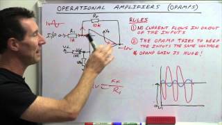
When looking at the inverting amplifier circuit, the equation for the circuit can be calculated from the simple formula Av = R2/R1.
For the non-inverting amplifier the gain is slightly different and can be calculated from the formula Av = 1+ (R2/R1).
It is also possible to use the non-inverting amplifier as a buffer amplifier with a unity voltage gain by looping the output back to the inverting input, i.e. R1 = infinity and R2 = zero. In this way the voltage gain can be calculated to be 1.
So in summary both inverting and non-inverting amplifier gain is easy to calculate using the simple formulas.
More information can be found at: www.electronic...
Also subscribe to our UA-cam Channel: / electronicsnotes


My professor wasted the whole entire classtime deriving the gain formulas and by the end of it I was exausted and didn't even know what an Op Amp did. Thanks for making this so simple.
Glad we were able to help!
And I'm here for the same reason...
One of the most beautifully explained opamps videos ever. Cheers to the creator🥂
Thanks for your comment. Really appreciate the fact that it helped.
This has been immensely helpful, THANK YOU!!
Thank you! simple and clear
You're welcome!
Sir,You are great! So thankful for this video.
You are most welcome. I’m glad the video was useful. Thank you.
Perfect. Thank you so much !
Thanks sir for your explanation 👍
Glad you found it useful.
I like how in my circuits class my professor keeps referring to gain and makes no explanation of what it is. Thankfully there is youtube.
Glad you found the answer.
Thumbs up, dude. A couple things worth pointing out:
1. No current flows into the inputs
2. Voltage difference between inputs is zero
Based on #1 above, we see that the non-inverting amplifier does not draw current from the input source. The inverting amplifier does draw current. So even though the ideal op-amp has "infinite" impedance, in inverting mode, that is no longer the case. This could be an issue for a source that has limited current capability.
Thanks for the comments
One of the clearest
Glad the video was helpful.
Thought this was one of them ridiculous Hindi videos with not even subtitles 😍
Hope you found it useful.
Crystal clear explanation 🙏🙏💯
Really glad you found it useful. Thank you.
straight to the point !
Glad the video was useful.
many thanks for the amazing video it been great help
Glad it helped
Can you remake that intro from 30 seconds to 2 minutes? It would be helpful for Electronics Engineers and the old ones like me, who need to brush up the old skills.Cheers!
I’ll take a look at that.
very clear
Glad you think so! Thanks for your comment.
This video really helped me!
👍
Glad we were able to help. Thanks for the comment.
Great video subbed and pinged that bell!
Thanks so much for this! :)
Great explanation
Thanks for your comment.
Thanks a lot, buddy!!!!!! 😎
Glad it was helpful
From a circuit analysis point of view, how does one come to the value of 1+(R2/R1) for the gain of a noninverting op amp ?
Hi, you can use two golden rules for an op amp as follows to solve that: There is no input current drawn into the op amps at all and there is a VIRTUAL short between the two inputs of an op amp(they are of same voltage). Using this and normal circuit tools like ohm's law, you will be able to get that gain. Hope it helps even if its after 8 months!
@@harinachiappansubramanian9206 Thanks! :)
@@GiraffeNVC No problem man, had to learn this op-amps topic online entirely for my project with no prior info, and youtube videos and comments saved me. Hope it helped you as well
nice video helps allot liked subed!
nice video-thumbs up
Thanks for you comment. Glad you liked the video.
@3:10 - how we can turn the amp up to 11
What's the difference between "amplification" and "gain" of an operational amplifier? Thank you in advance 4 your attention!
Well there is actually very little difference between the two terms - it's more semantics. People generally tend to talk more technically or specifically in terms of gain, i.e. it has a gain of ten, but use the term amplification for more general talk. You would rarely say it has an amplification of ten, but it would be quite correct in terms of the grammar, etc.
@@ElectronicsNotes thank you very much! I was confused. So they're practically synonyms, got it!
it is helpful
Where can I see more about the "and many more things" circuit at 0:15?
We have plans to do videos on more op amp based circuits, but in the meantime there are descriptions about more op amp circuits on our website: www.electronics-notes.com/articles/analogue_circuits/operational-amplifier-op-amp/circuits.php
Sir what is the nearly gain of operatioal amplifier?
Why the diagram is the same? 4:10
The two diagrams at 4.10 are different. In one the input is attached to the - or inverting input to provide an inverting amplifier, whereas for the other the input is applied to the + or non-inverting input to provide a non-inverting amplifier. Although in both cases feedback is applied to the inverting input as it is negative feedback, both configurations are different.
ElectronicsNotes Thank you i understand i am just wondering why both circuit is connected to - 😂
How to make an adjustable gain control should I use only potential meter instead of R2 or pot with series resistor
You could do it the way you suggest, but I would tend to feed the output across a potentiometer with the slider providing the output to the next stage.
If i want to try a mod on a low pass filter circuit, in order to increase gain, the change on r1 and r2 also changes the low pass frequence? Should i lower r1 or increase r2, if i want to increase gain? Can i use a pot in series with r2? Thanks.
It’s not always easy because you can upset the damping and cutoff frequency. You might like to read this article: www.electronics-tutorials.ws/filter/filter_5.html
Wrong symbol decleration of inverting and non inverting opams......
Is it possible to give 100% feedback on inverting amplifier without any resistor Because i want to make stereo power amplifier to bridge mode
Yes, the non-inverting configuration is often seen as a buffer with 100% feedback.
www.electronics-notes.com/articles/analogue_circuits/operational-amplifier-op-amp/non-inverting-amplifier.php
see it goes to eleven
why have a unity gain buffer, i never understood
The unity gain buffer is used to "buffer" the previous stage. The circuit has a high input impedance and low output impedance, thereby enabling a circuit that cannot be loaded to have the buffer to provide the low impedance output needed for other circuits.
hey! plz can u help me on how to Design and simulate an inverting amplifier with a gain of 150???
plz help
Unfortunately we cannot help with the actual designs as I would not be able to spend much time on the website. We get a lot of requests for help, but cannot deal with specific enquiries like this. I would though suggest that 150 is a very high gain level if you want to have any sort of bandwidth.
R2=150 kOhm R1=1kOhm :)
I know this was a year ago, but for anyone else seeing this and having a similar question:
Your gain is equal to R2/R1, if we have a gain of 150, we need any 2 resistors that combine such that R2/R1=150.
The easiest way would be ok 150/1, but that's not realistic for resistors, and OPAMPs require resistors of higher value (we used 10k/1k for my lab assignment at uni). So take your 150/1 and just multiply it by 1000. Thus, R2=150,000 ohms and R1=1,000 ohms.
@@TheRussell747 150k/100k = 1.5
👍
Anyone can show equations, could have derived or showed us how you got to that would've been much more helpful
Yes, it is possible to derive the equations as you can see onto e accompanying page to the video: www.electronics-notes.com/articles/analogue_circuits/operational-amplifier-op-amp/gain-equations.php When making he video I was very mindful of what people would want and the time spent on deriving the equations. My view is that most people will just want the equations - but may be I was wrong???
@@ElectronicsNotes No you were not. Thank you Sir.
@@ElectronicsNotes the video was great. It was short and to the point for those procrastinators of us (aka myself). I got the info I needed, and nothing extra, in an efficient and quick manner without feeling like it was all thrown at me at once.
But, you've also included the link, so those who wish to know more detail (like the guy being a prick about it), are able to instantly go to a reference that has the information they need; rather than spending 30 minutes just to find the relevant info first.
The video was great, keep doing what you're doing.
Circuits giving you a nigtmares? Pin Point androidcircuitsolver on google