I was confused about the sign of example 1 until I realized equation 2 should be (0-V0 ) = (50 microamps)(25K ohms), yielding V0=-1.25V. The voltage drop across the 25K resistor is 0-V0, which is the tricky part. In example 2, its strange to think about negative resistance (IMHO), so I'd suggest R = -V0/i1. It's the same math, just seems to better reflect what is happening in the circuit. In example 3, I believe the equation to compute V0 should be 2-V0 = (1mA)(5K) = -7V.
@@andy2a2m Yeah I think that's the answer too. It looks kinda like an inverting OP AMP so it checks out. Shame he didn't update a correction. I would've gotten tripped up too if I didn't go into the comments. Edit: Actually, no it doesn't. It looks more like a non-inverting OP AMP. I didn't take into consideration that current could be flowing from the output to the ground instead. Disregard my comment.
Truth be known, I'm obsessed with this device (and the transistor, LOL). I was a circuit board designer (mechanical layout of circuits) for years and was always impressed by the many uses I've see with op-amps. This video instills great confidence! Thank you for the time you put into making these videos!
Nice! Op-amps were so confusing to me at first but once I started to figure them out and saw how incredibly useful they are, I admit I got a bit obsessed as well.
I was also a PCB layout draughtsman - never ceases to amaze me how we were just seen as monkeys with tape (yes I am that old) when in fact we could quite often have to fully understand the circuit design to lay it out properly - we in fact had the same skills as the circuit designer - and then some. Nice video chap.
At 9:36, how do we know that the current through 2KOhM resister (i1) is the same as through the 5KOhM resister. Shouldn't the current be different on the 5Kohm side? Not intuitive there.
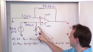
2:41 a small question as I have already seen similar explanation but one thing is not allowing me to sleep ;) why don't we add those resistances? I knoe that no current enter the inverting input of OpAmp but I see two resistors here 10 k and 25 k but we calculate current for the one of them 10k ? I don't get it. Normally to calculate the current I would add all resistors and divide it by the voltage right? for example 5V / 10 000 ohms + 25 000 ohms to get the total current ..or we just treat that 25k resistor as an "invisible" resistor for the moment to calculate the right output of the op-amp or something like that?
That's a great question. The reason we only calculate the current for the 10K resistor is because, in this question, we know the voltage across the 10K resistor (because we know the voltage at the inverting input) but NOT the voltage across the 25K resistor (because we don't know Vo). So, given what information we're given, we cannot calculate the current through both of them from the beginning. But we know they have the same current through them so we find the current through the 10K resistance and, with that information, we find the voltage across the 25K resistor, giving us Vo.
@@CircuitBread This still doesn't make sense to me. If we know no current is flowing into the op amp and instead passing through both resistors in series, why wouldn't you have to calculate the current such that i = .5/(10K+25K) like you normally would with two resistors in series? For example, imagine you just have a simple circuit with two series resistors with a 5V power source, then saying "let's just calculate the current using the first resistor and ignore the second one". What is special about the op amp that allows us to ignore that 25K resistor when calculating the current? Why doesn't this behave like two resistors in series leading to V_0?
@@rwharrington87 I had the same question, only rephrased to "what does the op-amp actually do?" And I guess here lies the answer: the op-amp output "draws" the necessary voltage, since it tries to make the inputs the same. And since we assume that there is no current flowing into the inputs, the 25k resistor sees i1 as current. Otherwise the op-amp wouldn't do anything at all... I hope someone can confirm or disconfirm this?
As he mentioned, you can just view this as a voltage divider. The current through flowing through the resistors is identical, as they are essentially in series configuration. This means taking the total resistance R = 4k + 8k, and dividing the voltage by it to get the current I = 3V/12k =250uA. Now to find the voltage drop over the 8k resistor, we just multiply the current through it by its resistance. V = 8k * 250uA = 2V Hope this helps :)
We have .5V from the source to the non inverting input, not from the source to the output. That means that between the source and non inverting output (where the potential is 0V) we have a .5V voltage drop, therefore we can calculate the current that goes through the 10K resistor. The voltage between the source and output is 0.5V+1.25V=1.75V, and if we apply ohm law we have i=1.75V/(10k+25k)=50uA, I hope this make it more clear@@abrahamjones3635
Another method of calculating Vout using the gain of the opamp. Gain=Vout/Vin, since same current I1 is flowing through both resistors, Gain=R2I1/R1I1=R2/R1=25Kohm/10Kohm=2.5. Vout=Gain*Vin=2.5*0.5=1.25V. The sign of Vout should be negative because the input on the inverting port of the opamp is higher than that on the non-inverting. So Vout=-1.25V
Hi sir!! I'm bavithra from Tamilnadu.I had a Cadence interview on April 28. I watched your video I was very useful sir. Thankyou sir for teaching me in understandable manner.But I need your help sir I didn't have enough materials to practice these type of problems.Can you refer any book for preparing my interview sir? Thankyou sir. I hoped you will reply to my comment sir.
I'm glad you found the information helpful! For further study, you can explore our textbooks available at www.circuitbread.com/textbooks. Utilize the search bar on the left to quickly locate topics of interest.
Seeing you get a bit lost in the solution made me feel slightly better about myself, lol. But it was well explained, and I've subscribed to your channel.
This doesn’t have nearly enough views! I would literally lose sleep over how op-amps worked and circuit analysis in general. Thanks to this I’ll sleep peacefully now. I really feel that the theory for electronic circuits is made overly complicated by those that are teaching this but the way you’ve explained this was straight to the point! Perhaps that’s something to do with limited application of their skills outside of an academic course. I think it’s brilliant you leave your mistakes in because, even though it’s simple algebraic operation still so easy to make a mistake. Seeing the reasoning is good
we dont know the voltage between the non inverting input and output, but we know that between the non inverting input and ground we have a 2V voltage drop, therefor we can calculate the curent that goes from node that connects the 2K and 7K resistor to the ground, which is 2V/2k=1mA. If 1mA exists that node, then 1mA needs to entry that node, and the only way is through the 7k resistor (KCL)
Another thing I would explicitly state for the pedagogy of circuit theory is that you should never do nodal analysis on Vout as it does not have the same assumptions for conventional nodes in that current does not accumulate in any node. I find that some of my tutees did not know this because it was simply implied but never clarified.
I am a bit confused between Example 2 and 3. How come in example 2 it is 0 - Vo but in example 3 it is Vo - 2V? (I am asking about the Vo being subtracted vs not)
Great question! It is somewhat arbitrary. As long as you state your current flow assumptions correctly, you can do it either way. So, in example 2, I assumed that current was flowing from the inverting input to the output. Whereas in example 3, I assumed that the current was flowing from the output to the inverting input. That's the only reason. I could have assumed the opposite and swapped those, but then the sign of the current (whether it was positive or negative) would have flipped, because my assumption of the direction would be different. Does that help?
I’m confused on that too actually, if you assumed current is flowing from high to low when solving for current down the 2kohm resistor wouldn’t it be from positive to negative across the 5kohm resistor as well (from the negative terminal to Vout)
To anyone that is still confused: In example 1: the 25k ohm is the feedback resistor Rf, the 10k ohm is the input resistor Rin, Because the supply is connecting to negative side, which means the signal must be inverted and amplified, The multiplier is Rf / Rin = 25k ohm / 10k ohm = 2.5, again, it is inverted, so it is -2.5 So the final answer, the output is 0.5V * -2.5 = -1.25V
In example 3, because the current path is only one way, so, we can use 1mA multiply by 2k + 5k ohms (they are in series, no current going into op amp as the rules stated), the answer is 0.001A*7000ohms, 7V !
This confused me when I was in college as well - we discuss it briefly in our intro video and are actually doing final review of another script that will touch on it again (at our pace, it will probably be another 1-2 months before it's published). Here's the one we did awhile ago: ua-cam.com/video/zH-5ls0YAI0/v-deo.htmlsi=hKlGOWLUR6hBOgak
Putting the formula their gives your brain more power to calculate other stuff. Basically like working memory on a pc. Weirdly enough we are wired quite similarly
Hi for example 1 could you explain why the current going through the 10k and 25k resistors was defined by 0.5V/10k Ohms instead of 0.5V/(10k + 25k) Ohms?
Hi Georgei! The important thing here is to remember that the inverting and non-inverting inputs to the op-amp are the same voltage level. Since the non-inverting input is tied to ground, you can assume that the inverting input is tied to ground. Thus, the current going through the 10K ohm resistor is found by (0.5-0)/10K. And, since you know no current goes into the input, you know that same current has to go through the 25K ohm resistor. I hope that helps!
@@CircuitBread I had the same question and you cleared it up perfectly! Thank you so much! Also, I just want to say how thankful I am that you answered this. Even though the video was uploaded 11 months ago.
Im actually still confused on this; if no current flows into the inputs then the only current path would be through both the 10k and 25k resistor right? So wouldnt the current flow be defined as .5 / (10k+25k) ?
@@mcpoogle9058 hi, I know this is an old comment but i will explain anyway. We have .5V from the source to the non inverting input, not from the source to the output. That means that between the source and non inverting output (where the potential is 0V) we have a .5V voltage drop, therefore we can calculate the current that goes through the 10K resistor. The voltage between the source and output si 0.5V+1.25V=1.75V, and if we apply ohm law we have i=1.75V/(10k+25k)=50uA, I hope this make it more clear
@@mcpoogle9058 Yeah I think we need a video between the introduction and this one that explains how the equilibrium is reached and how the voltage/current flows with respect to that second resistor. I definitely missed something or it wasn't explained fully.
i have a question . It might sound dumb you know normally in circuits when we they say current isnt flowing through tat wire they dont regard it why was it different in the first question
Kinda! This is actually an inverting amplifier and the equation for Vo/Vi is -R1/R2, so we could do -(25/10)*.5 to get the final output a lot faster. For most situations, you'd just use this equation to make your life simpler, but the idea was to show how to solve for op-amp problems utilizing the characteristics of an op-amp. For this, the learning is in the process more than the result. Hope that helps!
Hi Spencer! Since we know the inverting input is at 2V and the resistor to ground is 2K ohms, we know that the current through that resistor is 1mA. As the 2K and the 5K resistors are in series, the current through the 5K resistor has to also be 2mA. And that's how we find the output voltage of the op-amp. I hope that helps!
Great video... I was struggling with op amps, your video help me enormously. I have a question. How at 6:41 you get negative R? I rewatch that part many many times and still don't understand. Thanks!!!
Hi there! This is a problem that I've seen a lot and have definitely done myself. It goes back to first step where we show the equation as (0 - Vo)/R = i1 It is very easy to drop the 0 and forget that the negative sign stays! So that's where it's simplified to -Vo/R=i1 and then that negative sign switches over to the other side. Does that help?
Another way to state it is that (conventional) current always flows from a higher voltage to a lower voltage. So the zero volts at V+ *has* to be higher than what Vo is. Thus Vo must be negative valued.
Exactly! 0V or ground can be somewhat arbitrary. It's just a reference point and to have a negative voltage just means the voltage is lower than that arbitrarily chosen reference voltage level.
I don’t want to be the wise guy because I am not. Perhaps there is a small math error in the above video in the beginning 2:25 minutes in the video? U (Volt= V) / R (Ohm = Ω) = I (Amperes = A) therefor 5V/10KΩ i.e., 10000 Ω = 0,5 milli amperes or 0,0005 Ampere or 500µAmpers (Micro Amperes) not 50µAmpers. So 0.0005A x 25KΩ = 12,5 V not 1,25V. Ω=ohm symbol
Hey Bendt, I had no idea this was going to cause so many problems when putting this problem together but there have been many comments on this. The period in front of the .5V seems to be missed very easily. So, your math is totally right but with the wrong input. It's .5/10K not 5/10K, so the answer in the video is actually correct. I appreciate you taking the time to provide the feedback!
@@CircuitBread omg i cant believe i missed the "." 😂..reminder for me to pay close attention! Thanks again, btw perfect release time; I am prepping for my exams and opamps a big chunk of it!
The output should be -1.25 but you are correct about the amplification. I think the confusion comes from the input voltage, which is .5, not 5. .5 * -2.5 = -1.25
yeah, I just wasted 30 minutes of my life arguing with chatGPT over that one and I was right all along. Just had an existential crisis when it told me all my fomulas wouldn't work because "it's got a virtual ground" or whatever. I'm a little mad, but mostly relieved honestly. Can't believe nobody else caught it
Can you just show the process? Like in the third example with the voltage divider, please just do the math and show it. We’re not experienced like you and can’t just look at it and go “Oh it’s two volts”. This is what I always hate about educational vids like this is it’s always the most convenient problems they are solving when I will see nothing like that on any exam or problem
Phew, you scared me! I hate it when I mess up my math. In this case, you are correct with your math but you're reading it wrong. You're using 5V, not .5V. In the question, it is .5V/10K, which does give us 50 microamps. Thanks for the scrutiny and feedback, I *do* like to be corrected when there are mistakes, so don't hesitate if you see anything else that looks out of place.
Nice one. Suggest always to put a zero in front of a real number that only has a fractional part I.e 0.5 not .5 I was scratching my head because I thought it was 5 👍
can you explain how you dropped volts using simple math in 3rd question, when 3 volts passes 4R it drops one volt and when it passes thro 8R it drops 2V, how?... I ain't no math genius
The 3V are dropped over 12K ohms total. I'm not sure if it helps to think about it this way but, with 3V, it's easy to divide that 12K ohms into three parts and you will drop 1V per 4K ohms. So you'll drop one volt over that 4K resistor - giving you 2V at the non-inverting node. This is a semi-intuitive way to look at it but may not be the best when approaching it for the first time. The more rigorous way to do it would be to look at it like a voltage divider. I recommend checking out our tool on this that can help you calculate it, shows the actual equation, and can let you play with it until you get a better intuitive feel for what's going on: www.circuitbread.com/tools/voltage-divider
These were more the theoretical problems with op amps. The practice problems are much different, like: - the input current is not really zero, especially not in the case of bjt op amps - in certain cases you need to take care of the input offset voltage, especially in the case if you use op amps as comparators. - when you operate with pulse voltages at the inputs you have to make sure, that the operating voltage stays stable, even if you need to operate with a certain capacitive load at the output. So you have to use stabilization capacitors between the Vcc and GND pin of your op amp or two of them if you operate with a symmetrical operating voltage. Otherwise your circuit will fall into oscillations - the nonlinearities of the op amp input circuit can demodulate rf. So if you want to build up an audio amplifier it is sometimes necessary to use a low pass filter at the signal input to suppress rf interferences to avoid that you have some closely located radio station music in the background of your audio amplifier output. - if you need higher voltage amplifications (for microphone or phono signals), you need to make sure, that the gain bandwidth product doesn't compromize your amplifier at the higher frequencies. Also the input referred voltage offset and noise voltage become important in such application cases. etc.
It's complicated and I don't know how much of his personal life he'd want me to share but he's alive, healthy, and unbelievably stressed and sad. When I met him he was living in Mariupol and there'd be times we were talking during the 2014 Crimean invasion that there'd be explosions in the background, so that's why he moved to more central Ukraine. But Mariupol is where he grew up and he still has family there, so it's heartbreaking to see it as an active warzone.
Dang! It's always hard to find the balance between boring people with too many details or confusing people with too few details. Sorry that the balance wasn't quite right for you... For that, what happens is that the 1mA on the right gets multiplied by the 5Kohms on the left (to cancel it out of the denominator on the left), so .001A*5000Ω = 5V.
Haha, it’s amazing how many people comment on the toast not popping up. The toast/toaster is just part of our branding and we were originally going to do a bunch of different outros but never got around to it, so for a lot of our videos we just have the toast going down. I guess it adds some suspense. 😅
You are teaching some very bad information here. I’ve taken my time to see if it’s just interpretation, but it isn’t. 1. The voltages at the two input pins are NOT always the same! If they were, the OpAmp would have no use. An OpAmp is an ideal differential amplifier. That’s all it is. The voltage difference at the two opposite polarity inputs is the input signal of any differential amplifier. If there is no difference, as you say explicitly over and over, the output will always be 0v. 2. The output pin should be considered a perfect current sink. What’s a perfect current sink? Well, ground is. Treat it as ground for the purpose of feedback R value computations.
All of them? Any of them? Could you let me know what you're referring to? We've had questions in the past about these but it seems like the biggest mistakes he made was not investing in handwriting practice.


Mistakes make this learning experience even more real!
great video man, reminded me of how the ideal op-amp calculations work after almost a year of not doing them
Glad it was helpful!
I was confused about the sign of example 1 until I realized equation 2 should be (0-V0 ) = (50 microamps)(25K ohms), yielding V0=-1.25V. The voltage drop across the 25K resistor is 0-V0, which is the tricky part. In example 2, its strange to think about negative resistance (IMHO), so I'd suggest R = -V0/i1. It's the same math, just seems to better reflect what is happening in the circuit. In example 3, I believe the equation to compute V0 should be 2-V0 = (1mA)(5K) = -7V.
thanks for corrections, It made me understand. But In example 3, third equation; where is 5V comes from? Am I missing something?
from what you said 2-V0=5V, V0 will be -3V not -7V
the answer is actually 7 volts
@@mustafanaber 1mA*5k ohms
@@andy2a2m Yeah I think that's the answer too. It looks kinda like an inverting OP AMP so it checks out. Shame he didn't update a correction. I would've gotten tripped up too if I didn't go into the comments.
Edit: Actually, no it doesn't. It looks more like a non-inverting OP AMP. I didn't take into consideration that current could be flowing from the output to the ground instead. Disregard my comment.
Truth be known, I'm obsessed with this device (and the transistor, LOL). I was a circuit board designer (mechanical layout of circuits) for years and was always impressed by the many uses I've see with op-amps. This video instills great confidence! Thank you for the time you put into making these videos!
Nice! Op-amps were so confusing to me at first but once I started to figure them out and saw how incredibly useful they are, I admit I got a bit obsessed as well.
I was also a PCB layout draughtsman - never ceases to amaze me how we were just seen as monkeys with tape (yes I am that old) when in fact we could quite often have to fully understand the circuit design to lay it out properly - we in fact had the same skills as the circuit designer - and then some. Nice video chap.
At 9:36, how do we know that the current through 2KOhM resister (i1) is the same as through the 5KOhM resister. Shouldn't the current be different on the 5Kohm side? Not intuitive there.
i am writing on the 9th nov ,you saved me from lot of anxiety
very clear explanation. Thank you for taking the time out of your life to do this.
You are very welcome
2:41 a small question as I have already seen similar explanation but one thing is not allowing me to sleep ;) why don't we add those resistances? I knoe that no current enter the inverting input of OpAmp but I see two resistors here 10 k and 25 k but we calculate current for the one of them 10k ? I don't get it. Normally to calculate the current I would add all resistors and divide it by the voltage right? for example 5V / 10 000 ohms + 25 000 ohms to get the total current ..or we just treat that 25k resistor as an "invisible" resistor for the moment to calculate the right output of the op-amp or something like that?
That's a great question. The reason we only calculate the current for the 10K resistor is because, in this question, we know the voltage across the 10K resistor (because we know the voltage at the inverting input) but NOT the voltage across the 25K resistor (because we don't know Vo). So, given what information we're given, we cannot calculate the current through both of them from the beginning. But we know they have the same current through them so we find the current through the 10K resistance and, with that information, we find the voltage across the 25K resistor, giving us Vo.
@@CircuitBread This still doesn't make sense to me. If we know no current is flowing into the op amp and instead passing through both resistors in series, why wouldn't you have to calculate the current such that i = .5/(10K+25K) like you normally would with two resistors in series?
For example, imagine you just have a simple circuit with two series resistors with a 5V power source, then saying "let's just calculate the current using the first resistor and ignore the second one". What is special about the op amp that allows us to ignore that 25K resistor when calculating the current? Why doesn't this behave like two resistors in series leading to V_0?
@@rwharrington87 I had the same question, only rephrased to "what does the op-amp actually do?" And I guess here lies the answer: the op-amp output "draws" the necessary voltage, since it tries to make the inputs the same. And since we assume that there is no current flowing into the inputs, the 25k resistor sees i1 as current.
Otherwise the op-amp wouldn't do anything at all... I hope someone can confirm or disconfirm this?
Best description on op amps I've found yet... And I've looked around a lot. Subscribed! Thank you sir🙏🏾
8:20 Sorry. To me, this isn't as simple. How did you know to drop 1 volt over the 4k resistor and 2 volts over he 8k resistor?
Yessss
As he mentioned, you can just view this as a voltage divider. The current through flowing through the resistors is identical, as they are essentially in series configuration. This means taking the total resistance R = 4k + 8k, and dividing the voltage by it to get the current I = 3V/12k =250uA. Now to find the voltage drop over the 8k resistor, we just multiply the current through it by its resistance. V = 8k * 250uA = 2V Hope this helps :)
amazing explanation and bringing us in your mind to let us learn how to think while solving problems. thank you!
I never understood anything about those things. Seeing those 2 rules being applied made it all click. Thanks!
My question is why do'nt we consider the 25K resitor when we are calculating I1? Isn't the same current I1 flowing through both resistors?
That's exactly what I was thinking, if you found an answer please let me know.
We have .5V from the source to the non inverting input, not from the source to the output. That means that between the source and non inverting output (where the potential is 0V) we have a .5V voltage drop, therefore we can calculate the current that goes through the 10K resistor. The voltage between the source and output is 0.5V+1.25V=1.75V, and if we apply ohm law we have i=1.75V/(10k+25k)=50uA, I hope this make it more clear@@abrahamjones3635
I have the exact same question.
Another method of calculating Vout using the gain of the opamp. Gain=Vout/Vin, since same current I1 is flowing through both resistors, Gain=R2I1/R1I1=R2/R1=25Kohm/10Kohm=2.5. Vout=Gain*Vin=2.5*0.5=1.25V. The sign of Vout should be negative because the input on the inverting port of the opamp is higher than that on the non-inverting. So Vout=-1.25V
great explanation
how do u calculate in the third practice problem the 2 volts. cause i dont understand that part
So because there is a voltage divider you use Vin ( R2 / R1 + R2 ) to get Vout. Which is 3v ( 8k / 4k + 8k ) giving you Vout of 2v.
All understandable in a easy way ! Thanks good buddy !
at 9:08 why did he find the current across i1?
Hi sir!! I'm bavithra from Tamilnadu.I had a Cadence interview on April 28. I watched your video I was very useful sir. Thankyou sir for teaching me in understandable manner.But I need your help sir I didn't have enough materials to practice these type of problems.Can you refer any book for preparing my interview sir? Thankyou sir. I hoped you will reply to my comment sir.
I'm glad you found the information helpful! For further study, you can explore our textbooks available at www.circuitbread.com/textbooks. Utilize the search bar on the left to quickly locate topics of interest.
Seeing you get a bit lost in the solution made me feel slightly better about myself, lol. But it was well explained, and I've subscribed to your channel.
This doesn’t have nearly enough views! I would literally lose sleep over how op-amps worked and circuit analysis in general. Thanks to this I’ll sleep peacefully now.
I really feel that the theory for electronic circuits is made overly complicated by those that are teaching this but the way you’ve explained this was straight to the point!
Perhaps that’s something to do with limited application of their skills outside of an academic course.
I think it’s brilliant you leave your mistakes in because, even though it’s simple algebraic operation still so easy to make a mistake. Seeing the reasoning is good
Thanks! I'm still self conscious of my mistakes but I hope they help people somehow. And, particularly, I'm glad this was helpful to you!
Sir, thank you for this explaination and including the mistakes that I do.
Nice video, thanks.
In the last example, I think you have 1mA flowing through 2kΩ + 5kΩ, which gives us 1mA * 7kΩ = 7V
we dont know the voltage between the non inverting input and output, but we know that between the non inverting input and ground we have a 2V voltage drop, therefor we can calculate the curent that goes from node that connects the 2K and 7K resistor to the ground, which is 2V/2k=1mA. If 1mA exists that node, then 1mA needs to entry that node, and the only way is through the 7k resistor (KCL)
Excellent and straight forward. Thank you.
circuit bread #1 fan right herreeee
Another thing I would explicitly state for the pedagogy of circuit theory is that you should never do nodal analysis on Vout as it does not have the same assumptions for conventional nodes in that current does not accumulate in any node. I find that some of my tutees did not know this because it was simply implied but never clarified.
I am a bit confused between Example 2 and 3. How come in example 2 it is 0 - Vo but in example 3 it is Vo - 2V? (I am asking about the Vo being subtracted vs not)
Great question! It is somewhat arbitrary. As long as you state your current flow assumptions correctly, you can do it either way. So, in example 2, I assumed that current was flowing from the inverting input to the output. Whereas in example 3, I assumed that the current was flowing from the output to the inverting input. That's the only reason. I could have assumed the opposite and swapped those, but then the sign of the current (whether it was positive or negative) would have flipped, because my assumption of the direction would be different. Does that help?
I’m confused on that too actually, if you assumed current is flowing from high to low when solving for current down the 2kohm resistor wouldn’t it be from positive to negative across the 5kohm resistor as well (from the negative terminal to Vout)
Understood this topic, thanks!
To anyone that is still confused:
In example 1:
the 25k ohm is the feedback resistor Rf,
the 10k ohm is the input resistor Rin,
Because the supply is connecting to negative side, which means the signal must be inverted and amplified,
The multiplier is Rf / Rin = 25k ohm / 10k ohm = 2.5, again, it is inverted, so it is -2.5
So the final answer, the output is 0.5V * -2.5 = -1.25V
In example 3, because the current path is only one way, so, we can use 1mA multiply by 2k + 5k ohms (they are in series, no current going into op amp as the rules stated), the answer is 0.001A*7000ohms, 7V !
In the second example could you write the final answer as R= -Vout/i
I am confused about the negative voltage, do you have a video that explains what that negative voltage means?
This confused me when I was in college as well - we discuss it briefly in our intro video and are actually doing final review of another script that will touch on it again (at our pace, it will probably be another 1-2 months before it's published). Here's the one we did awhile ago: ua-cam.com/video/zH-5ls0YAI0/v-deo.htmlsi=hKlGOWLUR6hBOgak
Putting the formula their gives your brain more power to calculate other stuff. Basically like working memory on a pc. Weirdly enough we are wired quite similarly
Why isn't I1 calculated using the equivalent resistance? I am confused.
Hi for example 1 could you explain why the current going through the 10k and 25k resistors was defined by 0.5V/10k Ohms instead of 0.5V/(10k + 25k) Ohms?
Hi Georgei! The important thing here is to remember that the inverting and non-inverting inputs to the op-amp are the same voltage level. Since the non-inverting input is tied to ground, you can assume that the inverting input is tied to ground. Thus, the current going through the 10K ohm resistor is found by (0.5-0)/10K. And, since you know no current goes into the input, you know that same current has to go through the 25K ohm resistor. I hope that helps!
@@CircuitBread I had the same question and you cleared it up perfectly! Thank you so much! Also, I just want to say how thankful I am that you answered this. Even though the video was uploaded 11 months ago.
Im actually still confused on this; if no current flows into the inputs then the only current path would be through both the 10k and 25k resistor right? So wouldnt the current flow be defined as .5 / (10k+25k) ?
@@mcpoogle9058 hi, I know this is an old comment but i will explain anyway. We have .5V from the source to the non inverting input, not from the source to the output. That means that between the source and non inverting output (where the potential is 0V) we have a .5V voltage drop, therefore we can calculate the current that goes through the 10K resistor. The voltage between the source and output si 0.5V+1.25V=1.75V, and if we apply ohm law we have i=1.75V/(10k+25k)=50uA, I hope this make it more clear
@@mcpoogle9058 Yeah I think we need a video between the introduction and this one that explains how the equilibrium is reached and how the voltage/current flows with respect to that second resistor. I definitely missed something or it wasn't explained fully.
i have a question . It might sound dumb you know normally in circuits when we they say current isnt flowing through tat wire they dont regard it why was it different in the first question
Superb video 🎉🎉
excellent explanation 👍🏽
Why in second problem o -vo was taken but in last problem it was opposite?
i confuse that why at third problem you said its gonna be 2 volts sir
In exercise 1, since this is a non inverting amplifier, couldn’t we use (25/10)0.5 ?
Kinda! This is actually an inverting amplifier and the equation for Vo/Vi is -R1/R2, so we could do -(25/10)*.5 to get the final output a lot faster. For most situations, you'd just use this equation to make your life simpler, but the idea was to show how to solve for op-amp problems utilizing the characteristics of an op-amp. For this, the learning is in the process more than the result. Hope that helps!
How did you get 1ma across the 5k resistor in problem 3? Shouldn't that be 0.4ma ?
Hi Spencer! Since we know the inverting input is at 2V and the resistor to ground is 2K ohms, we know that the current through that resistor is 1mA. As the 2K and the 5K resistors are in series, the current through the 5K resistor has to also be 2mA. And that's how we find the output voltage of the op-amp. I hope that helps!
@@CircuitBread Ah thank you. I was following the current from the wrong pin so I didn't notice that they were in series.
Great video... I was struggling with op amps, your video help me enormously.
I have a question. How at 6:41 you get negative R? I rewatch that part many many times and still don't understand.
Thanks!!!
Hi there! This is a problem that I've seen a lot and have definitely done myself. It goes back to first step where we show the equation as (0 - Vo)/R = i1 It is very easy to drop the 0 and forget that the negative sign stays! So that's where it's simplified to -Vo/R=i1 and then that negative sign switches over to the other side. Does that help?
Another way to state it is that (conventional) current always flows from a higher voltage to a lower voltage. So the zero volts at V+ *has* to be higher than what Vo is. Thus Vo must be negative valued.
@@CircuitBread if we subtracted 2v from Vo in equation that would give -3v. is this correct?
I am confused, how can there be a -1,25 volts on the Vout? Shouldn't that be positive? Just need some help. Sorry for the dumb question.
I think I get it, it is a negative signal compared to ground? Correct?
Exactly! 0V or ground can be somewhat arbitrary. It's just a reference point and to have a negative voltage just means the voltage is lower than that arbitrarily chosen reference voltage level.
Thank you!
You're welcome!
Good job.
Cool video, well done, thank you for sharing it :)
Thanks for watching!
I don’t want to be the wise guy because I am not. Perhaps there is a small math error in the above video in the beginning 2:25 minutes in the video? U (Volt= V) / R (Ohm = Ω) = I (Amperes = A) therefor 5V/10KΩ i.e., 10000 Ω = 0,5 milli amperes or 0,0005 Ampere or 500µAmpers (Micro Amperes) not 50µAmpers. So 0.0005A x 25KΩ = 12,5 V not 1,25V.
Ω=ohm symbol
Hey Bendt, I had no idea this was going to cause so many problems when putting this problem together but there have been many comments on this. The period in front of the .5V seems to be missed very easily. So, your math is totally right but with the wrong input. It's .5/10K not 5/10K, so the answer in the video is actually correct. I appreciate you taking the time to provide the feedback!
@@CircuitBread yeah, putting .5 instead of 0.5V was a mistake, easy to overlook the point.
hey! love the vid! I seem to be getting -12.5V for question 1 because my i1 value is 500mu Amps, not 50mu Amps..?
Thanks! Did you happen to use 5V instead of .5V? That seems to be the most likely cause making your current 10x what it should be.
@@CircuitBread omg i cant believe i missed the "." 😂..reminder for me to pay close attention! Thanks again, btw perfect release time; I am prepping for my exams and opamps a big chunk of it!
Had missed it too.
Thanks 👍
In the first problem, the output should be -12.5V, not -1.25V. The closed loop amplification of the inverting amp is -2.5 not -0.25 (Acl = 25k/10k)
The output should be -1.25 but you are correct about the amplification. I think the confusion comes from the input voltage, which is .5, not 5. .5 * -2.5 = -1.25
I also felt in this trap. Did calculations with 5v instead of .5v
The answer is -12.5 V for first problem
yeah, I just wasted 30 minutes of my life arguing with chatGPT over that one and I was right all along. Just had an existential crisis when it told me all my fomulas wouldn't work because "it's got a virtual ground" or whatever. I'm a little mad, but mostly relieved honestly. Can't believe nobody else caught it
Can you just show the process? Like in the third example with the voltage divider, please just do the math and show it. We’re not experienced like you and can’t just look at it and go “Oh it’s two volts”. This is what I always hate about educational vids like this is it’s always the most convenient problems they are solving when I will see nothing like that on any exam or problem
For practice problem 1, 5V/10K-ohh is not 50 micro-amps, it will give 5e-4.
Phew, you scared me! I hate it when I mess up my math. In this case, you are correct with your math but you're reading it wrong. You're using 5V, not .5V. In the question, it is .5V/10K, which does give us 50 microamps.
Thanks for the scrutiny and feedback, I *do* like to be corrected when there are mistakes, so don't hesitate if you see anything else that looks out of place.
Nice one. Suggest always to put a zero in front of a real number that only has a fractional part I.e 0.5 not .5
I was scratching my head because I thought it was 5 👍
That has caught a couple of people - I'll try to remember to do that in the future. Thanks for the feedback!
can you explain how you dropped volts using simple math in 3rd question, when 3 volts passes 4R it drops one volt and when it passes thro 8R it drops 2V, how?... I ain't no math genius
The 3V are dropped over 12K ohms total. I'm not sure if it helps to think about it this way but, with 3V, it's easy to divide that 12K ohms into three parts and you will drop 1V per 4K ohms. So you'll drop one volt over that 4K resistor - giving you 2V at the non-inverting node. This is a semi-intuitive way to look at it but may not be the best when approaching it for the first time. The more rigorous way to do it would be to look at it like a voltage divider. I recommend checking out our tool on this that can help you calculate it, shows the actual equation, and can let you play with it until you get a better intuitive feel for what's going on: www.circuitbread.com/tools/voltage-divider
I1 = 5 /10 k
= 0.5 milli amps or 500 micro amps (not 50 micro amps)
Voltage drop across 25 k ohms= 0.5 ma* 25 k
= 12.5 volt
Vout = - 12.5 v
These were more the theoretical problems with op amps. The practice problems are much different, like:
- the input current is not really zero, especially not in the case of bjt op amps
- in certain cases you need to take care of the input offset voltage, especially in the case if you use op amps as comparators.
- when you operate with pulse voltages at the inputs you have to make sure, that the operating voltage stays stable, even if you need to operate with a certain capacitive load at the output. So you have to use stabilization capacitors between the Vcc and GND pin of your op amp or two of them if you operate with a symmetrical operating voltage. Otherwise your circuit will fall into oscillations
- the nonlinearities of the op amp input circuit can demodulate rf. So if you want to build up an audio amplifier it is sometimes necessary to use a low pass filter at the signal input to suppress rf interferences to avoid that you have some closely located radio station music in the background of your audio amplifier output.
- if you need higher voltage amplifications (for microphone or phono signals), you need to make sure, that the gain bandwidth product doesn't compromize your amplifier at the higher frequencies. Also the input referred voltage offset and noise voltage become important in such application cases.
etc.
How is Sergei these days?
It's complicated and I don't know how much of his personal life he'd want me to share but he's alive, healthy, and unbelievably stressed and sad. When I met him he was living in Mariupol and there'd be times we were talking during the 2014 Crimean invasion that there'd be explosions in the background, so that's why he moved to more central Ukraine. But Mariupol is where he grew up and he still has family there, so it's heartbreaking to see it as an active warzone.
@@CircuitBread sorry to hear that. send him best wishes and thanks for his great work.
The gain is 2.5 so output voltage is -12.5 v please edit video
The input voltage is .5, not 5. So -2.5 *.5 = -1.25 not -12.5V - those decimal points can be easy to miss!
It would be useful for dunces like me if you explained the 'obvious'🤔 simple maths, I have no idea how you got your 5V from in the last equation
Dang! It's always hard to find the balance between boring people with too many details or confusing people with too few details. Sorry that the balance wasn't quite right for you...
For that, what happens is that the 1mA on the right gets multiplied by the 5Kohms on the left (to cancel it out of the denominator on the left), so .001A*5000Ω = 5V.
@@CircuitBread Thanks for that. Not a complaint, I loved the pace of the video just my math isn't up to scratch so ended up rather confused😮💨
kilo -> k
Kelvin -> K
me waiting for the toaster to pop up...................
what's the use of the toaster at the end? I didn't get it. 😂
Haha, it’s amazing how many people comment on the toast not popping up. The toast/toaster is just part of our branding and we were originally going to do a bunch of different outros but never got around to it, so for a lot of our videos we just have the toast going down. I guess it adds some suspense. 😅
9:04
Do some quick Meth? No thanks, it's too early.
😂 And here I get on my kid's case for speaking clearly...
I m the 555 th person liked this vid . 555 a great symbole for the great ic 😅 thank sir for the vid
You are teaching some very bad information here. I’ve taken my time to see if it’s just interpretation, but it isn’t.
1. The voltages at the two input pins are NOT always the same! If they were, the OpAmp would have no use. An OpAmp is an ideal differential amplifier. That’s all it is. The voltage difference at the two opposite polarity inputs is the input signal of any differential amplifier. If there is no difference, as you say explicitly over and over, the output will always be 0v.
2. The output pin should be considered a perfect current sink. What’s a perfect current sink? Well, ground is. Treat it as ground for the purpose of feedback R value computations.
its not 50 micro amps .. its 500 micro amps ... so the output should be -12.5 V I suppose
we have 0.5 V, not 5V, it's easy to mistake because he put .5
🤨
whats up with the toaster
The fact that we show a toaster or that the toast doesn’t pop up?
try to be careful with your solutions, so many errors and we are learning from you.
People make mistakes as long as he catches them it’s fine
There is a good chance he makes them on purpose to show where you can make mistakes. Similar to electro boom
👁🔺
His answers were wrong
All of them? Any of them? Could you let me know what you're referring to? We've had questions in the past about these but it seems like the biggest mistakes he made was not investing in handwriting practice.