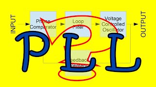
This is the best explanation of a loop filter I have ever seen. Not only pure theoretical, but with a practical switch, which makes it easier to grasp.
I'm not a regular youtube commenter, but I feel like I really have to in this case. I follow your channel closely, your videos are very valuable to me. They provide a lot of theoretical insight, yet are practical enough to not forget why you are explaining/learning this. I also like that you take the time to explain things very thoroughly, making things look very simple even though I wouldn't even know where to start when researching these things myself. I hope you keep on producing these nice videos!
I totally agree with the other commenters You did a great job with your explanation. I like how you didn't just start in the phase domain. It makes sense to look at PLLs in the phase domain but I personally find it rather unintuitive so starting in the frequency domain made it very clear for me. I recently experimented with adding an adder in the loop filter and adding on an audio signal to implement FM modulation. It was quite interesting to get it stable but it worked out pretty well in the end. Looking forward to the next part, generating the actual circuit from a high level control model like this is another quite complex task.
Very nicely explained the role of the zero!!! I came to your videos while I was troubleshooting spurs of my PLL. Looking forward to videos on bandwidth vs noise of all kinds and lock time. Keep up the good work Sir!
Good explanation. I see in practice the oscillations in the loop with wrong designed filter. It is a rare tutorial for PLL where this concept is described.
incredible job! this explanation is gold, i don't like when in youtube videos an explanation is dirt simple or out of reach complex but yours was just perfect to understand with basic knowlage. please keep on going! 73, IU3IRR
I always wondered really what was meant by Phase Margin in a loop filter...you made this so clear in this video, thanks for the lesson -I'm now subscribe and your English is fantastic to me; keep em coming.
I like how you pronounce error hhh. I like how you try so hard and repeat yoursel over and over to explain and give the audience a chance to digest the idea. I also understand english isn't your native language so it's hard for you to express your ideas easily. overall I like your sharing your projects. thanks.
You trying to correct someone else's pronunciation(I am glad you did because I didn't understand what he was saying!!!), but you also made "a-hor" on your spelling of "yousel" instead of "yourself".
Thanks! If you think that the transfer function of the filter is from current to voltage, you will see that in both cases (only the capacitor, or the lead compensator) have the 40db/dec at lower frequencies (pole at 0Hz)


Support the channel becoming a Patron
patreon.com/allelectronics
After watching this, now I understand how VCO vs low pass filter matters. Thank you GREAT TEACHER!
🙏🏼🙏🏼🙏🏼🙏🏼
This is the best explanation of a loop filter I have ever seen. Not only pure theoretical, but with a practical switch, which makes it easier to grasp.
Thanks!
I'm not a regular youtube commenter, but I feel like I really have to in this case. I follow your channel closely, your videos are very valuable to me. They provide a lot of theoretical insight, yet are practical enough to not forget why you are explaining/learning this. I also like that you take the time to explain things very thoroughly, making things look very simple even though I wouldn't even know where to start when researching these things myself. I hope you keep on producing these nice videos!
Thank you!!
I cannot tell you how incredibly well you presented this topic. You have helped me understand so much. I can't thank you enough.
Thank you so much man!!
This video is fantastic--thank you so much! I love how you explain the fact that the VCO is an integrator for the phase!
I totally agree with the other commenters You did a great job with your explanation. I like how you didn't just start in the phase domain. It makes sense to look at PLLs in the phase domain but I personally find it rather unintuitive so starting in the frequency domain made it very clear for me.
I recently experimented with adding an adder in the loop filter and adding on an audio signal to implement FM modulation. It was quite interesting to get it stable but it worked out pretty well in the end.
Looking forward to the next part, generating the actual circuit from a high level control model like this is another quite complex task.
Bravo! This was a beautiful explanation 👏
Thanks!
Very nicely explained the role of the zero!!! I came to your videos while I was troubleshooting spurs of my PLL. Looking forward to videos on bandwidth vs noise of all kinds and lock time. Keep up the good work Sir!
Glad it helped!
Good explanation. I see in practice the oscillations in the loop with wrong designed filter. It is a rare tutorial for PLL where this concept is described.
Glad it was helpful! You can learn these fundamentals by studying classical control theory.
@@AllElectronicsChannel I have studied it, but it was about 20 years ago )
excellent understanding PLL
Thank you!
incredible job! this explanation is gold, i don't like when in youtube videos an explanation is dirt simple or out of reach complex but yours was just perfect to understand with basic knowlage. please keep on going!
73, IU3IRR
Thanks!
I always wondered really what was meant by Phase Margin in a loop filter...you made this so clear in this video, thanks for the lesson -I'm now subscribe and your English is fantastic to me; keep em coming.
Thank you so much Camo! Welcome to the channel!
Nice explanation of theory behind pll filter, looking forward to your ltspice simulation video and the advanced topics..
I like how you pronounce error hhh. I like how you try so hard and repeat yoursel over and over to explain and give the audience a chance to digest the idea. I also understand english isn't your native language so it's hard for you to express your ideas easily. overall I like your sharing your projects. thanks.
Thanks man!!
thanks man, i was stuck at "a-hor"
You trying to correct someone else's pronunciation(I am glad you did because I didn't understand what he was saying!!!), but you also made "a-hor" on your spelling of "yousel" instead of "yourself".
Tuque tuque redisfleg 🙏🏼🙏🏼🙏🏼
Great video very clear and understanding even if it's not my native language (French) thank you
Welcome to the channel, Frederic!
Excellent explanation!
Simply excelent! I thought that the second capacitor added at min 24 was already take it in account on the phase detector transfer.
Thanks! If you think that the transfer function of the filter is from current to voltage, you will see that in both cases (only the capacitor, or the lead compensator) have the 40db/dec at lower frequencies (pole at 0Hz)
Awesome explanation!!
Glad you think so!
Thank you so much bro for sharing your knoweldge , you have a magic technique to explain things , god bless you inchallah
Thanks and welcome!
where were you Gregory when UA-cam started.. lovely lecture as always been
Hahahahaahah
Muito bem explicado ! Seus insights fazem a diferença. Keep up the good work !
Thanks!!
Great Work!
🥳🥳
thank you :D
Excellent.
Thanks!
A question how to filter SDM?
Can you explain power monitoring circuit
damn, this is sooo good
very good.👍
Thanks for the visit
What does VCO mean
Voltage Controlled Oscillator