{1081} Very complicated Repair, SMPS input short circuit, no output

Вставка
- Опубліковано 4 сер 2024
- In this video number {1081} Very complicated Repair, SMPS input short circuit, no output . when connected to series test lamp, lamp gives full illumination indicating short circuit, no output voltage. i demonstrated step by step troubleshooting and repair
TO SUPPORT THIS CHANNEL;- Bank account IBAN;- PK94 HABB 0008 4779 0028 4403
Title; MUHAMMAD ASHRAF. Swift code; HABBPKKA / HABBPKKA007. Habib Bank Limited, Chowk Azam
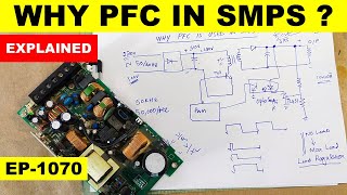
In this video number {1081 } I explained how to repair delta electronics PMC-24V300W1BA 24 volt 12.5 ampere EOE13010225 switching power supply. its repair and troublshooting process was very complicated due to short circuit in power MOSFETs, their gate drive components, pulse trtansformer, PFC section rectifier S6J 6 amper, 600 volt SMC / DO-214AB rectifier, A2 smd marking zener diode UDZV 5.1B 5.1 volt zener diode
5IN smd diode MMSD4148 Switching diode, 200V, 200mA,
pulse transformer one winding open circuit
You are Invited to Join Haseeb Electronics
/ @haseebelectronics
Please check other videos
SMPS no output • {966} SMPS Is not work...
SMPS step by step repair tutorial • {528} How To Repair SM...
How to download circuit diagram, service manual • {558} How To Download ...
Transistor, IGBT, MOSFET equivalent • {233} How to find Equi...
Broken plastic gear repair • {679} How To Repair Br...
You can Follow me on :-
Instagram: / haseebelect
Facebook: web. profile.php?...
#deltaelectronics #24vsmps #repair
00:00 how to repair delta electronics thailand 24 volt smps
00:52 24 volt smps no output voltage
02:20 MOSFET gate drive components damaged
03:03 smps input short circuit
04:11 pfc section troubleshooting - Наука та технологія


Awesome repair. You asked for suggestions and all I can humbly ask for is that when you check components that you say what you are checking and what you are checking for. For instance, when you checked the 1n60c3 mosfet, explain that there is a diode between the source and the drain and that's why you get .5 volts when you put the positive meter lead at the source and the negative meter lead at the drain. Also that you need to turn the mosfet on by putting the positive meter lead on the gate to turn it on and then turn it back off by reversing the leads. It should be noted that not all meters have enough positive voltage on them to turn on a gate. A current limited supply is a MUST for every bench, even if made with an lm317 regulator and two 9 volt batteries to simulate a positive and negative rail.
Your videos have so much information in them, that I hate to make any comment at all. I DO LOVE that you've added written descriptions to the faults you find and what then readings should be. Anyway, your videos are perfect the way that you make them, so take my suggestions however you want, you're still the best power electronics videos out there! Thanks for all you do!
No need to explain everything or the video will be longer..anyone with fair amount of electronic knowledge will understand what he is doing his videos are not for beginners.
@@fmforever4 Yes, I was reluctant to comment this and realized that the length of the videos would be lengthened. Maybe once in a while is better. Oh well, my two cents. I do like the shorter length videos. He does break down these components in other videos. Thanks for your input.
Very tricky repair, avesome metod! It has been very interesting follow you along the time! 😊
Sir we are happy because you are with us in this situation I don't have a kind person to help but we are luckily got you. You most talented and good quality.God Bless you sir.and I hope surely God bless you sir. We love you so much sir
I enjoyed this great adventure with cup of coffee!!! Nice problem and hard of course. Nice repair!!! My humble thanks.👍👌👍
Coffee and Haseeb is how I start my mornings! I'm "lost" the days there are no new Haseeb videos! Ha Ha.
Very good Bhai, best idea to remove diode with 2 ,25watts soldering irons 😊 too much smd parts to remove.ok very best job done 👍
Thanks and welcome
Very nice video. Good faultfinding and good explained.
Really need more patients sir. Hats of to you❤
Great work
Amazing, very difficult reparation but well solved. Great wonderful explanation. Thanks a lot
You are welcome
As I previously watched the video in that case the problem will find after the fuse . Thanks sir
It would help a lot if you explained how the power supply got damaged. The chain of destruction.
A very interesting repair, thankyou.
Do you have any idea what caused the failure, as it seems a significant amount of components were damaged across multiple circuits.🤔.
Thanks for the great videos, keep up the good work. 👍
Wooow, Soo soooo informative, this vid one of the most important vid I have ever seen, many tricks, we really need like this vid with different faulty components, please Haseeb more vids we need like this one. Many many thanks for your amazing efforts.
Nice vedeo, informative and knowledgeable vedeo. Thank you so much. God bless you.
You are most welcome
Great work Mr Haseeb !!!....
¡Gracias!
Thanks a lot 💕
Super
Ooooovvv. Çok zorlu bir tamir oldu. Yedek parça hazinesi iş gördü. Yaşasın eski parça deposu😅😅😅. Tabii usta tamirciyi unutmayalım😅😅😅👏👏👏
👏👏👏👏👏
Very nice information. Thank you sir.
👍👍👍
awesome job
Sir thanks very informative vedio sir please explain the solar inverter without battery which knows Khan inverter in Pakistan
Sir vedio ko urdu may banai bahut mehrbani Hogi
I am from Pakistan
welcome bhai
i will try to arrange solar inverter
urdu mein ye video 24 April 2024 ko upload ho gi
Jazakallahu khaerah,,, 👍
Thanks for sharing
Hola mi estimado Haseb , muy dsñada esa fuente , sospecho de un mal diseño , los MOS suelen ser engañosos, antes de medirlos siempre pongo en corto las terminales , se cargan muy fácilmente y muestran un corto , tambien suelen funcionar sin el PFC , tengo algunas de esas delta , suelen fallar , he tenido dificultad para encontrar sus diagramas , muy instructivo tu video , eres un profesional , un abrazo !!!
Emeğine sağlık efendim. Pfc bölümde köprü diyot pfc kontrol entegresi veya mosfet arızası olabilir.
This was a great video. Thank you. What are the pulse transformers used for in a smps?
A lot of work to repair the power supply 😮
👍
❤❤❤
The quality of your microscope video camera is much better than your normal video camera, Please upgrade your primary video camera quality 👍🏻
thanks a lot for your valuable suggestion. sure i will try to upgrade it soon
@@HaseebElectronics what is microscope camera?
it is Andonstar Digital Microscope 407,
you can check video number 807 for more details
ua-cam.com/video/w6Bf2R1piOA/v-deo.html
@@HaseebElectronics Maybe you can make a list of equpments you use, and put them in description of every video.
❤❤❤😮😮😮
How are these Delta SMPS getting blown up? What is the customer using these for?
What confuses me is expecting diode readings to be of high resistance one way and OL the other. But some diode readings have resistance both ways and are still considered good?
Sir I have a ATX power supply and make it regulated voltage control by seeing your video and it's work. But it is not maintain the voltage properly, if I connected load it can not maintain voltage. why, give me a solution.
If its a short circuit the fuse should blow so fault is either before the fuse or is not a short circuit but maybe switching device is faulty with mains connected directly to transformer.
Sir, Thank you very much for making this video. Sir, kindly help me understand what was the cause of failure of this power supply. Secondly, in such a huge short circuit, why didn't the Fuse blow off. Thank you very much in Advance. God is with you. Take care.
Every short has non-zero resistance. If the resistance is high enough the fuse won't blow (or the fuse was defective which is extremely rare). Why it failed? Fan stalled, semiconductors overheated and eventually shorted. Shorted mosfet passed high voltage to the gate and wrecked havoc.
Hello Haseeb. I have a pheonix contact industrial smps 24v 10a. The following problem persists.
When connected to mains with a series lamp, the lamp glows and doesnt turn off. I did the following inspection.
I seperated the primary from the secondary section. Now when connected the lamp glows for a few seconds then goes off. I have stable voltage at main capacitor and vcc capacitor. I reconnected the secondary. Now again the lamp glows but i have stable 24v in output section.
What could be the fault.
Stable input voltages, all components good, diodes good, stable output voltage, but the series lamp keeps glowing. Could it be the IC or the optocoupler? Please guide.
If the fuse is OK than the short is not in the primary part but could be a partial short in the secondary part of the SMPS
Salam, i believe it might be something that shorts with a resistance just enough to glow the lamp but not enough to blow th fuse, maybe bridge or small short in the SMPS transformer...
Haseeb sir what is instrument name which you are using to clear Pth hole. Please share instrument name and if possible let me know from where to purchase
it is WELLER WR3M rework station
made in Germany
you can purchase online from indiamart
www.indiamart.com/proddetail/weller-wr3m-3-in-1-high-end-electronic-pcb-soldering-9437196497.html?pos=7&kwd=weller%20wr3m&tags=A||||7554.316|Price|product|||TS|stype:attr=1-br|qr_nm:gd|res:RC4|com-cf:nl|ktp:N0|mtp:Brn|qry_typ:P|lang:en|wc:2
many reasons CX capacitor or the two cy, Bridge , Mosfet , IC PWM , Filter capacitor,mov
THANKS FOR GRAET JOB COUDLE YOU PLASE SUGGEST ANY HOT GUN FOR REPAIRE SMD BORED ATMID PRICE WITH 110 INPUT VOLTAGE THANKS ADVANCE.
I think the pfc switching is stuck means the mosfet will be short drain and source joint together.
Nice repair sir...did you use the same board for the spare parts? Would it be possible to fix the board using a generic SMPS?
Thanks
Yes i am getting parts from a scrapped same model power supply.
Used parts are more reliable and cost effective
hi Herr haseeb Bitte how to chick sefuse D6x9z0
Danke
What is the reason of this type fault when fuse not burning out but, half shot circuit,,,, high voltage why not work mov,,,, voltage fluctuations why not work capacitor,,, wht is the reason,,, behad shukriya
Short between live and neutral after fuse.
Dear Sir,thanks for your useful contents,What do you propose for testing an automatic relay stabilizer input voltages(140-170-190-220-240) without Variable Ac Power Supply?
Variable ac source is good
VERAIC brand variable auto transformers are very useful for variable voltage
@@HaseebElectronics Really appreciated for your advice. But asking "without Variable Ac Power Supply", I ment instead of using variable auto transformer, what can I do?Do you have any alternative way for this?
@@amirsh4633 Appropriate sliding resistor and a voltmeter. Or resistor network.
The bridge rectifier IA shorted
Mov short,,, bridge rectifier short not fully short out put side short or semi short
Mosfet
Haseeb sir, I have a question. I have one 12V 30A SMPS. I tried to upgrade it to have 36V at the output. I changed its output capacitors to 50V, changed the diodes and changed and increased the secondary coil turns (it was 4 earlier, I made it 12) and I also changed the feedback resistances. It tested the SMPS with 60W series lamp and it worked normally and the lamp didn't glow at all, the SMPS was giving 36V at the output but when I connected it directly to mains one of the primary transistors gets shorted. I replaced the transistors and tried two more times but every time when I connect the SMPS directly to mains, one of the switching transistors gets damaged..
Can you please help me find what I am doing wrong here and what should I do next? All other components like diodes, small transistors and capacitors are good in the SMPS. The SMPS is based on TL494 IC and works on half bridge topology. The SMPS also has an NTC of 4.7ohm for current limitation.
Please Please help me out.🙏🙏🙏🙏
You can't modify the secondary like that. Your power transistors see your transformer as an non-linear impedance, not just resistance. Transformer has a core, and you are driving it into saturation. When the core *saturates* your transistors will die. Lamp helps because it will limit saturation current to a level that the transistor can withstand. But this is not your only problem. Let's say your power supply is 80% efficient. 12V * 30A = 360W. It's losses (heat) is 360*0.2=72W. By boosting it's output voltage 3 times, you've increased its losses at least 3 times. I mentioned only the basics, leaving out advanced considerations.
But I have not changed its primary winding and it still follows it's turns per volt consideration, so there is nothing for the core to saturate at no load. I haven't applied any load to the SMPS in all the tests..
@@subhasishbhaduri2938 Transformer is an impedance convertor. By changing its secondary you've changed its characteristics. When you turn on the SMPS for the first time, empty capacitors on the secondary are behaving like the short circuit. Anyway you can measure the current waveform on the primary side with an oscilloscope and see if the saturation occurs. Please let me know the results of the measurement.