Creating a Spectrum Analyzer using an Arduino and a Non-Inverting Operational Amplifier

Вставка
- Опубліковано 20 сер 2024
- This is a summary of everything I learned trying to create a Non-Inverting Operational Amplifier circuit in order to feed an audio signal from a soundbar to an Arduino microcontroller so I could drive LED lights based off of the music playing.
Hope this is helpful and that I didn't make an egregious errors in the video lol.
Once I have the project setup inside my van I'll upload the source code I used.


That was absolutely fantastic. Your explanation of the circuit theory and practical application was formatted and delivered perfectly for me to grasp the concept.
Thanks I've gotten a lot of feedback from people who seem to know what they're talking about, I think the final design isn't too great but it worked, the whole digi-pot solution is convoluted imo. This was mostly me trying to learn new things through trial and error and trying to slap solutions together to whatever problems I encountered lol.
Auto Gain control in preamps like this is traditionally done using a JFET and a peak detector circuit. The JFET serves as a voltage-controlled "potentiometer".
you don't need 2 power supplies, for negative voltage make Virtual Ground with a voltage divider with 2 resistors and 2 caps of same value
Correct !
;)
even better would be to use a second op amp as a v-ref
Works for logic levels, but better is if you use zeners and transistors. I use that for amplifiers and it works great. Also, it removea a lot of hum and hiss
i literally was watcing about single rail supply and vitual ground yesterday thats funny
You can not use that on OPA, because they draw too much current which makes the voltage collapse.
Ive watched several videos on this subject. What stands out from all the other videos is the fact you cover way more theory, if I had found this video in the beginning of my venture I wouldn’t know all the things you didn’t cover here. Thanks for all your time and energy. It helped more then you could know.
Thanks! Glad it helped some.
The ATMega328p ADC reads a signal between 0 and the voltage on the AREF pin. Optionally, you can configure the mega to connect AREF to the its internal voltage reference, roughly about 1.1V, making it pretty ideal if you had a positive signal from 0-1V.
There are many ~6V opamps with RRIO (rail-to-rail, input & output) that let you use the [almost] full swing of voltages from top (5V) to bottom (0V) of the power supply rails you give them.
Automatic gain for the win. Long ago I made a circuit to "listen" to music and flash neon to it. I made a wide range AGC. I could plug the input into a wall socket and it would be fine, yet it could pick up the signal from a turntable without a preamp.
Nothing bad happens if you connect the opamp output to negative input. It will operate in it's most linear region and will act as a buffer.
Fantastic video. Your detailed explanations were very helpful for my novice level understanding of op amps. This is a project I might try to build.
Thanks! If you do try, I'd highly recommend trying to find a soundbar with a pre-amplifier output line, or to just ignore the whole digital potentiometer idea entirely. Trying to solve these issues on the fly lead to this becoming more convoluted than it needed to be. A good learning experience, but not a great final design!
As far as the .ino code to control the LED lights, there's several really good videos on youtube already that show how to do that.
Very well presented! From a seemingly simple plan to bias and amplify your audio signal to it getting overly complicated quickly. I'm not an expert but I've been working on a similar problem to condition the audio signal for input into a microcontroller ADC. I've picked up some ideas examining a few simple Arduino based tiny oscilloscope circuits and such. May I suggest a few alternative solutions
Most importantly tho you could do with a pre-amplified 'line-out' from your source, I see this had already been mentioned by another poster here. Double-check if your sound-bar has it already, it should be a 3.5mm audio jack hole. This will save you a major headache by cutting out the convoluted 'auto gain control' system you are designing and you can get back to your simpler original design! Still it will be good experience nonetheless building something that complicated, it may come in handy somewhere else 🙂
I haven't looked up the specific op-amp you're using but I know that there are rail-to-rail op-amps available that will allow your signal to go nearly to the supply voltage limits without clipping
You don't specifically need to wire the op-amp to 'non-inverting' mode, the inverted signal will work fine for your spectrum analyser and the circuit will be simpler
But if you decide you want to keep it non-inverted then remember you have a pair of op-amp in the 8pin package. The circuits I've seen have the biasing and the gain done on separate stages , not sure if there's an advantage to it this way or maybe it's simpler
Try the LM27762 chip to drive the negative side of your op-amp, it generate the negative supply voltage via charge-pump circuit from the positive. This chip can be invaluable in situations like this 😉
Hope you find some of the above suggestions useful. I guess there is no right or wrong way, just what you may find is suitable for your circuit
Thanks for the thought out comment, I agree that this project quickly became convoluted as I attempted to understand and solve the issues I ran into. Much more a walk through of my learning experience than anything.
I found little to no good documentation out there on how to use an op-amp the way I wanted to and hopefully my video and further comments like yours can point others in the right direction.
@@himynameischris2175 can u give clear circuit diagram
The only signal conditioning crucial for driving an MCU is to keep the voltage on the input pins from swinging below ground or above the MCU supply rail. The simplest way to do it is to use a rail-to-rail opamp like the MCP6002 and drive it from the same supply as the MCU. If you must use a TL072, then put an appropriate Zener (or TL431) across the MCU input pins and drive it from the TL072 output via a 10K resistor.
It should not make any difference whether you use a line-level output (≈ 500mV) or output level (≈ 2V) from the soundbar. You still will want an adjustable gain somewhere between 1-2 or 10-20 or so, so you can match differing music levels. Just use a plain, old-fashioned log potentiometer for R2 and adjust it as required to get an output range just below clipping.
The TL072 will swing to within about 500mV of either rail, so it's not too bad, considering its age. Nevertheless, a rail-to-rail opamp with a single 5V or 3.3V supply will save a lot of design headaches.
The only issue with using an audio opamp in non-inverting mode is that the input impedance is simply the input resistor, which is likely to be considerably less than the input impedance in non-inverting mode. However, if the source impedance is low then it's not a problem.
The advantage of using the second opamp to supply the bias point is that it mustn't be left floating, so you have to tie its inputs somewhere. If you connect your 2.5V bias directly to the second opamp's non-inverting input and then connect its output to its inverting input, you can use its output as a very stable 2.5V reference in order to bias the first opamp. That kills two birds with one stone.
You don't need a negative voltage supply, and switching regulators (e.g. charge pumps) are inherently noisy. I really wouldn't recommend using them in audio applications. HTH.
very nice. It's so good to see analog still being taught; alan, retired analog engr.
The way you bring us along through the project development is really good!
Impressive. Great narration and video effects. I learned very much today. Keep up the great work.
Thanks, glad you liked it
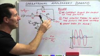
I'm a novice with electronics. However, one small correction. My understanding is that the inputs of an op-amp never have current flowing into (or out of) them. When you were concerned about the digipot being 0 and currently leaking into the inverting input, that would NOT happen. In fact, when the output is directly connected to the inverting input like when the digipot is set to zero ohms, the op amp just becomes a buffer with a gain of 1. It's actually a common use of an op amp when the source has high internal impedance and you need it to drive a circuit with low impedance.
See Dave Jones "EEVblog #600 - OpAmps Tutorial - What is an Operational Amplifier?"
You definitely have a career in Electronics dude! Keep up the good work, you brought back memories to me from back in the day whew I was playing with breadboards and stuff, congrats and thank you!
There is input leakage current in the opamp. This favors lower resistors. Additionally input capacitance can limit frequency response if feedback resistors are too big. Input offset voltage need not be considered because the dc gain is low.
If that's a dual op-amp chip you can use it to generate a virtual ground circuit to both bias the input signal and eliminate the need for a second voltage source.
I like the idea and the concept of where you were going but did have an issue with the op amp. If the sound input has a brief peak of high energy, the output level could exceed the input specification of the ADC input on the micro controller. And more than likely, there will be a significant excursion past those limits at power up due to the position of the capacitors in the circuit. Or if anything went wrong on the op amp side, you could be dumping about -10 or +10V on the input pin. A quick solution might be to add a resistor between the op amp and the microcontroller, to limit the current flow into the protection diodes on the chip. I generally like to use a rail to rail op amp running at the circuit voltage (usually 3.3V for my designs)., this means i don't need extra voltages and automatically provides a limit on the output within the acceptable range of the ADC input. And no negative voltages either. For a circuit like this, an inexpensive op amp like the MCP6001/6002(dual) would probably be fine. This part is also available in a DIP package as I recall which will make it easier for you. Pretty cheap as well. There are tons of other acceptable op amps from Microchip, Texas Instruments, Analog Devices and others.
Also, you generally don't have to worry too much about the feedback drawing too much current to the - input, the inputs are usually very high impedance. As long as the overall divider doesn't exceed the capable output current of the op amp, there shouldn't be an issue. Staying in the 10K to 100K range is usually a good compromise, if the impedance gets too high, bandwidth could suffer due to input and stray capacitance and be more likely to pick up noise. For low frequencies, I generally work around 10K, for analog video I will use 1K or less.
Also, don't forget a bypass cap on the power pin(s), it will help keep things stable and keep noise lower.
For biasing, I would have probably just used divider resistors to power and ground directly on the + input, eliminating an extra resistor and cap. I don't believe the slight noise improvement of the extra parts will help here, especially with good, stable and clean power supplies.
Those are just my suggestions. Keep learning, sharing and trying new things. If you can get your hands on an old National Semiconductor Linear Applications book, it will help open up a big analog world. I think the earlier 1978 to 1982 versions were best (in my opinion). Good luck and keep going.
Thanks for the input, I have a background in computer science but the electronics side of things I'm iffy on. The video was mostly the product of me just trying to teach myself this stuff and learn by trial and error, I'm sure I could redesign it to be a lot better/smarter. It's difficult finding good sources for info on specific things like op-amps online.
I'm away from home currently but I want to do a followup to this when I'm back.
The AREF pin can be provided with any voltage desired between 0-5V, and will define the top voltage for ADC conversions when analogReference(EXTERNAL) is called. Using this pin requires reading the manual and some calculation, since a 32K resistor is connected to it.
Of course, you still need to shift or discard the negative voltages.
There is also INTERNAL1V1 for 1.1 volt, and some have AR_INTERNAL1V0 for 1.0 volt, which means you don't need to amplify that extremely in the first place.
Some things to mention.
You should add series resistor and 2 clamping diodes in parallel to ground (a zener and a reversed shottky) for extra protection.
Also, by setting a different vref on mcu, you could reduce required gain. The uno has a vref pin as well as an additional internal 1.1v vref.
If you set vref low enough, you may be able to remove the opamp entirely with limitation on minimum amlitude for best results.
"You should add series resistor and 2 clamping diodes in parallel to ground (a zener and a reversed shottky) for extra protection. " ....to the input from the RCA plug ?
please elaborate.
X9C104 can be 0 ohms without causing ANY problems. In fact, virtually any modern OP_AMP can work as a VOLTAGE FOLLOWER or BUFFER, by connecting inverting input directly to the output.
Yup they are literally made to be not only be stable but have a at least 45deg phase margin as a follower
Yes I was going to say that too. As long as R2 is high enough to limit the current to sane levels R1 can be 0. Opamp pins have really high impedances and would just act as a buffer as you've said.
Cool video. Great explanation.
Great video! WIll definitely use it when I finally assemble my analyzer
Hello, subscriber 438 here. Happy to discover your channel. I look forward to your future projects.
That was beautifully clear. Thank you. :)
Just use a second opamp. Power them both at 24V and then use the second amp as a buffer for a two-resistor voltage divider to produce a virtual ground. Reference everything to this and you have +/-12V from your single bench supply.
Looking forward to more of your tutorial videos (electronics related). Very good explanation.
I'm traveling, but plan on continuing once I'm back home. I'm excited to revisit this and do it better.
It would have been easier and more linear to use the TL072 in an inverting setup powered with a 5V single ended power supply. The absolute polarity of the audio signal is irrelevant in this application. This way you set the DC offset (bias) with a voltage divider on the non inverting pin. This way the bias does not mess with the audio input of the circuit. This is probably why your signal was so non linear when approaching clipping as the signal was skewing the bias. Also a simple resister/diode on the output would give you a simple "crowbar" protection of the Microcontroller's input.
The snag is that the TL072 doesn't swing rail-to-rail, so you'd lose up to around 1V of your 5V range. Something like an MCP602 is designed for interfacing directly into an MCU and isn't expensive, also the unused amp is a good way to derive a solid 2.5V bias point. Using a 4.7V Zener (or a TL431) on the output via a 10K resistor would provide both positive and negative protection for the MCU.
Not really. The input cap decouples the previous stages so that's not why. The linearity is similar for both. The reason for clipping is that the opamp just isn't rail to rail
@@thewhitedragon4184 Agreed. The linearity is very slightly worse in non-inverting mode because both inputs must rise and fall with the input signal, so any non-linearity in the common-mode response is mixed into the output. With any decent opamp it's an almost negligible effect, though.
The TL072 has garbage output swing. It's a decent audio amp but you need like ±5V to operate it. Meaning you'd need like 9V supply or 12V supply minimum. That being said it's noise and distortion are great. It's a good preamp if you have a higher supply voltage or just need to get an electret mic to like a 100mV
@@thewhitedragon4184 Actually, the TL072 with a single 5V supply has a typical output swing from 0.18V to 4.3V under light loads, which was a lot better than many of its contemporaries when it became available in the late 1970s. The real problem was phase inversion and lock-up on the negative swing.
I think that to call its output "garbage" is a bit of modern revisionism, because for audio use (especially with high-impedance sources), it was the only affordable solution for many years.
I do agree that higher supply voltages make it a much more tractable device, though, and its high frequency drive performance with ±15V rails is still the best at its price.
btw, most of the gain control can be done in hardware. feed a copy of output into a full wave rectifier (using another op-amp), divide by 2 via resistors, feed into a peek detector then into a comparator comparing to half mcu vcc, take the logic pin of comparator and put on the up/down pin. for increment pin supply a 20khz (recomended) clock through an and gate (could use nand doesn't matter), the other input comes from an or's output. one or input comes from the comparator, the other comes from a gain increase enabler (could be a comparator-triggered time delay or a button to vcc and resistor to gnd or a pin on mcu to trigger via ir or wifi or bluetooth).
Fairchild/Onsemi makes a really nice photo-FET optocoupler, the H11F3M, that can act as remote voltage -controlled resistors whose value can be changed over a wide range from 100Ω to 300MΩ by changing the current through the photodiode input. A simple diode/resistor/capacitor from the output of the opamp to drive the photodiode with around 1-10mA will produce a 10:1 change in the resistance that can be used as the feedback resistor to make the simplest practical agc circuit. The only snag is that HF11F series is a bit pricey at around £3.50 for 1 off from Mouser.
Input impedance of OpAmp is so high you don't have to worry 'bout currents it sinks.
Ideal OpAmp has infinite input impedance. For your application you may consider any single chip OpAmp you choose as ideal one.
"I managed to kill my second digi-pot by accident" got me right in the feels, and I've got 40 years experience.
Beautifully explained, Many Thanks Sir..
... Rather than connecting to a variable signal, I would have connected a small amp in parallel with the soundboard input, so I could have a strong consistent signal regardless of speaker volume.
Great tutorial
Thanks for including the schematic diagrams.
With a single audio signal, it makes no difference if it gets inverted or not.
If working with an alternating signal into an opamp with a monopolar power supply, use the series input capacitor as shown, and follow it with a bias voltage sufficient to bring the output within the power supply rails.....the video shows this, but only for the reason of not presenting negative voltages to the Arduino. BTW, if after amplification by a positive-only opamp circuit, it is desired to have the signal be bipolar/alternating again, follow the output with another series capacitor, then a resistor to ground to re-bias.
And you would want to run the signal through several bandpass filters, one for each bar and then sampling them individually to get a true spectrum representation.
he must be running Fast Fourier Transform on the Arduino to separate the frequency bins for spectrum representation. Which is accurate enough if the sampling window size is large enough, however, higher the sample window, higher the processing latency.
I tend to not use breadboards, exactly for one of the reasons you evoked, it's impossible to know if it's wired correctly but with flaky connections or if you fucked something up. At first I thought it was making me waste components, but by building up circuits modularly enough I now think it's not really worse. Of course I'm just a beginner so take this with a grain of salt :)
I used a lot of breadboards in school and yeah they can be flaky with connections and really like to make oscillators
@@jhoughjr1 oscillators that quickly turn into fireworks
@@fmdj sometimes but op amps don’t have the magic smoke that electrolytic caps have
You could have routed microcontroller Vcc to the analog circuitry, then divide it in two to make proper desired bias voltage for the input AC signal. Then just simply use rail-to-rail OP Amp, like TLC271 (TLC272 for drop-in TL072 replacement), or newer TLV9101(TLV9102 for drop-in replacement).
However, why throw away a perfectly good TL072 already in your possession? Regarding the signal diving too close to negative (ground) rail, resulting in clipping, you could have used 2.5V bias inside the amplifier powered by 5V, but add another AC coupling capacitor between output of your amplifier and analog input of your microcontroller, with DC biasing (using microcontroller 3.3V Vcc ) on microcontroller side of the output capacitor.
Truly tidius, hardworking but Yes comes with it ideas, innovations things beautiful for all
A very low r1 is not a problem: the inputs on the op amp are high impedance, and the other path is 100k
Also, the inverting configuration is probably more flexible without any downside.
I wish you were my lab instructor
At 2:47 "More detail's better, right?" Quite right, so why not amplify the signal up to ± 5V and simply clip off the negative half before feeding it into the arduino? You would get double the resolution, since the negative half of an audio signal contains just the same information as the positive half.
At 9:14 "having the resistance of R1 near zero is probably a bad idea". No, it really isn't. It's quite normal for an opamp to be used as a non-inverting buffer, where the output is connected directly to the inverting input. Opamps are designed to work like that, and the current drawn by the inputs is normally quite negligible, certainly for audio applications. There really is problem with "leaking" or "current drain" through the feedback. The TL072 has an output impedance of 0.25Ω and can easily supply 50mA, so stop worrying about current draw.
As @Joel Styler pointed out, you must have something like a 100nF ceramic capacitor across the supply close to the IC, as it's crucial for stability. I also agree with him that high impedance means noise pickup and high-frequency loss due to stray capacitance. You could easily drop your feedback resistors down by a factor of 10 or more to improve noise immunity. You're certainly more likely to see R2 around 1K in practical audio circuits.
You also need to tie the unused opamp's inputs to something, rather than leaving them floating. The best bet is to tie the unused non-inverting input to the 2.5V bias voltage you already have, and tie the unused inverting input to the unused output.
The most important improvement you should make to the circuit is to clip the signal going into the Arduino to keep it in the range between ground and 5V. A simple way is to use a TL431 as a 5V Zener across the Arduino input and drive it from the opamp output via a 10K resistor.
If you now know that the output is constrained to the range 0-5V, then the digital pot -- fun as it is to play with -- is complete overkill. A simple trim pot for R1 will be more than adequate and will allow you to quickly set the display to match the music level.
The value of Cfilter sets the frequency at which the gain starts to roll-off and for audio use we would normally set it so that its reactance equals R2 at around 20Hz. That implies a capacitor of around 100nF if R2=100K or 10μF if R2=1K.
You don't need two supplies. Many opamps are designed to be used with single-supply. The TL072 is a BiiMOS opamp and is described in its datasheet as "wide-bandwidth high-output-drive single supply" and it was quite good for its time. Nowadays, there are CMOS opamps that can swing to within less than 100mV of either rail, so one of those (e.g. MCP6002) would be a good upgrade.
Finally, it is good practice for automotive use to remember that the supply voltage can be anywhere from around 12V to 14V, depending on whether the engine is running. So the usual way to make the bias point independent of the supply voltage is to use another TL431 as a 2.5V Zener in place of your R3, ensuring that the non-inverting input (and hence the output) stays at 2.5V regardless of the supply voltage.
I think I would use a Schottky diode (for removing the negative half) and analogReference(INTERNAL); statement.
While the theory of the non-inverting op-amp is fine, there are a few problems here. First, powering your op-amp from 12V in order to drive a 5V microcontroller is crazy, as it will eventually result in its death. Just having too much noise (e.g. touch input wire) or having a poor connection on a wire will be sufficient to inject 12V into it. Second, I'm not even sure the digital potentiometer is designed to stand 12V (which might be how you killed the other one). You absolutely need to use the target power to power your chip. Another point, instead of having an automatically adjusted bias you could just use the more common virtual ground using 2 resistors and have the output centered around half of the power voltage. It would accurately pass the amplified input to the uC and you would have no clipping. Finally, connecting this to a microcontroller is not a good application of a non-inverting amp, because it's much easier to invert the value in the uC (use 1023-Ain and that's done), and for a spectrum analyzer you don't even care about the polarity at all!
Your Arduino has a stable 3.3 V regulated output, which makes you independent from the varying voltage from the battery.
Unless the battery voltage gets close to 3.3V
If I may, add 1 more resistor in your input between the input cap and the the mix point of the offset voltage. google: op amp summing amplifier, you will see each input as an input resistor. This is basically what you have done, the offset voltage is just another input to be summed. you have inline on that one, but missing the inline on the input. overall good job
Unfortunately, an opamp operating in non-inverting mode isn't a summing amplifier. If you want to mix two or more inputs, you need a virtual ground and that only occurs at the inverting input.
There is no point in placing a resistor in series with the input in the non-inverting configuration as it would do nothing other than create a resistive divider between itself and the 1M resistor used to bias the non-inverting input for dc.
I'm confused about the gain range you chose, being about 1 - 3x
If max P2P is 1v, then your max output would be 3v. But that's your max gain against max input. If your input volume is much less, you can't increase your gain to compensate, you've already maxed it.
I like this video
When you said "we don't want to invert the signal" my immediate thoughts were "but why though?". You're already digitally processing the signal to spling the bands, which I like, but any phase shift (in this gain multiplying with a negative is a 180 deg phase shif) in the signal isn't going to be reflected in the amplitude spectrum. Plus you could have just multiplied by -1 digitally.
Yeah I suppose inverting it or not doesn't affect it in the end, good point.
The buffer 74125 chip is not helping here. I'm assuming you are powering it through 5V, which according to the datasheet, would make the threshold for a high signal be 3.15 volts. I think that's not exactly the progress you have hoped for. I believe you wanted to make a logic level shifter that would accept 3.3V logic and output 5V logic, which you also don't need.
The datasheet of the X9C104 states that anything above 2 volts is considered a high input and anything below 0.8 volts is considered a low input, so the logic signals from the ESP should be more than suitable
One more thing, what's up with resistor R6 seperating the 5V of the ESP from the X9C Digital Potentiometer and the 74125 chip? why do you want to limit the current if you are using a supply voltage that's well inside the range of recommended operation parameters?
I want to make a followup to this video where I get a new soundbar with a pre-amplifier output line so I can eliminate the sloppy digi-pot idea all together. Then I also want to go over arduino code for a circuit with just an op-amp. I never posted arduino for this video because the digi-pot ordeal made the code very convoluted and I figured it was nigh impossible to follow, which kind of defeats the purpose of a guide/demonstration like this.
If I recall, R6 was put in to limit current flow going into the digi-pots Vcc. I had 2 of those digi-pots, and the first one I used died shortly after using it, I assumed I killed it with too much current on that line.
i see a slight problem coming. some songs etc. have long durations of low to no amplitude. to fix this you would need a delay of 1 minute or more before attempting to raise gain. ideally, adjustable to your preference or by using a button to manually raise to peak.
Good video. Too bad you don't have more of those. (Electronics. How to do stuff. Etc)
wouldn't this be easier to use a wider voltage input adc with higher bit count and just read the i2c or what ever output?
a headphone amp would put the the potentiometer on the input signal before the opamp
That is the dustiest arduino I have ever seen lmao
great video!
Brilliant!
👍🏻👍🏻👍🏻
Huh? Your Powersupply has two rails already, + (red), + (black) and GND (green). Also every ComputerPSU has + and - 12V rails.
Hey Chris I'm ready to build this now 😃 in the description it says you uploaded the source code but I can't find it. Any help would be appreciated 🙂
But you did not show how to feed audio in arduino and then drive the leds
Is the input voltage that you're getting from the phone connectors the equivalent to the output voltage you would get if you used 1/8 inch headphone jack?
If I understand correctly you're going from RCA phono connectors into your circuit. I'm wondering what the deltas would be to use it with a headphone jack.
I really liked the video until you added the digital potentiometer which isn't a proper way to do this, instead the signal should come from the pre-amplifier circuit. Thanks for sharing by the way. And will you make one for the software too?
Yeah my main goal with the video was just to share what I learned, the issues I ran into, and how I went about solving them. I'm no expert so I'm sure there's better ways but I found very little info online about using op-amps the way I wanted to.
The reason i never ended up posting the arduino code to go with this is pretty much because the code is super tailored to how I wired this stuff up and kinda convoluted so I figured it would be pretty darn hard to read and understand what going on. Plus there's several other good videos on UA-cam that go over the code for this pretty well.
Recently I had the idea of creating a followup to this video where, once I'm back from my road trip, I take into account some of the feedback I've gotten on this video so that I don't need the overly complicated digi-pot idea. That way it'd be nice and simple and I could upload the .ino code too. It'll be a while till then though.
Thanks, but to be honest: to use d-pots for the bias-voltage control, an calibration routine and a digital switch ( aka transistor ) to protect the adc input while calibration was the obvious choice and took just 2.5 sec to work out in theory…
What’s the purpose of R5?
When using dividers as a voltage reference, you wanna make sure you don't draw current from that node otherwise your voltage drops. For a circuit like this it isn't really needed since the input impedance of this opamp is on the order or TOhm, basically infinite, so no current will flow out of that reference node.
You are using similarly to a pull-up resistor, where that node will be set to the reference point via R5, but in this case you don't really need it.
Too bad your soundbar doesn't have a true "line out" which would mean that the output level is unaffected by the volume control, that would avoid having to build an AGC as you did. You'd also run into the same problem using a "headphone out" which would have some amplification built into it.
Well a soundbar with that would definitely be something to specifically look for if I was going to build another project like this. Didn't know that was a thing.
@@himynameischris2175 I was originally drawn to your video because I have a similar problem with a spectrum analyzer I am building. I want it to work with both line out and headphone out without having to have both the master gain (from input source) and an additional gain (with a knob) to feed the analyzer. Having studied the problem, I think your approach is not convoluted, you definitely need some form of AGC. I'd prefer not to go the digipot approach, instead I would prefer something more "analog" that doesn't require uC support. One approach I've come across is using an LDR/LED (i.e. "vactrol") from the output to adjust the gain. I haven't yet tried it, but it seems like a simple solution that may meet my needs. If you search youtube for "automatic gain control LDR", you should find some relevant videos.
Also, you might have been able to keep your single ended 5v supply with an OPA341 or LT1013.
@@Enigma758 great comment! nice video, Chris. I think you could get much the same effect by doing AGC digitally. more bits will sound better, but since you're just driving a spectrum analyzer display you'd end up with a similar display. in other words, take the highest sample minus the lowest sample in the last X samples (the envelope, or volume) and use that to normalize the signal. small envelope = more gain and vice-versa. You'd still need an op-amp circuit to shift and amplify the signal, but you could use a regular potentiometer to trim the ADC input signal so it never went over the max voltage then leave it alone. using a digital pot is pretty cool I must admit :)
@@RealJohnnyDingo I've decided that AGC is not what I want since I also want to display VU. AGC = compression and that works against a VU meter. My current approach is to use a rail to rail op amp and even so, running it at a higher voltage than the ADC range. I am using a zener to clamp the output so as not to damage the ADC. I still need a pot since I want utilize as much of the ADC resolution as I can. Furthermore, since I'm not using AGC, I need to pot to adjust the gain from different sources.
Right... EXCEPT, THIS IS NOT A SPECTRUM ANALZYER
this is a Graphic Equalizer
if it were a spectrum analyzer
you would have at least 1 input to sample the signal coming in.
Audo would not come out
Instead you would have Parametric readings
You would have properties of the signal such as
PER BER
POST BER
M.E.R.
S.N.R.
Q.E.F.
etc etc
Hence THE INSTRUMENT IS ANALYZING something
and has a quantifiable reading
what do you have
a bunch of blinking lights reacting to an audio file
NOT EXACTLY THE SAME THING
is the code ready?
Hi Chris, if I want my audio signal to read from my mobile phone for example how would I do this? Also how did you get your speaker to play the music and send that audio signal to the op amp. I am just abit lost on how you take the raw signal and get it to the arduino and to play at the same time.
Also what Op-Amp did you use, Thanks :)
Getting a signal straight from a phone (using the 3.5mm audio jack) might be tricky but I haven't tried that. In the video, I was connecting my phone (or laptop) to the soundbar I bought via Bluetooth. The soundbar I bought has a variety of wires/connections, one of which was the two RCA plugins that will repeat any audio signal the soundbar is playing (I read this in its manual).
If you don't want to use a soundbar, I wonder if simply buying a female 3.5mm port and connecting your phone to it using a male to male 3.5mm wire would do the job. That might work, but I'd have to try it myself to be sure. That might also introduce the varying voltage based on volume issue I was having with my soundbar when really you want the sound level to not affect the voltage amplitude.
I thought I said it in the video but I used a TL072 op-amp.
@@himynameischris2175 Okay got ya. The second half of the video was all about aliviating the voltage delta based on the volume of the the audio signal, but what if the volume was fixed, would you even need to have changed anything?
🌟🌷🌟
compartilha o codigo ino
?
AVR can easily do FFT should you nuke the Arduino firmware and just code ASM ;) Tried it, one op-amp to somewhat crank the input up and it is all done.
What is AVR? Haven't heard of that.
@@himynameischris2175 The 8-bit core later used in Arduino boards. Guess an ESP (which at least has a higher clock) could do FFT even under FreeRTOS.
Hi is your source code ready?
share ino code for arduino
I'd recommend watching this for a walkthrough of the code:
ua-cam.com/video/Mgh2WblO5_c/v-deo.html
The code I wrote is sloppy and very specific to how I was testing the different parts.
Darn, I came here for the software - I know op-amps, oh well (poor title selection)
since the Arduino is reading only positive signals on the analog ports why didn't you use a germanium diode to clip the negative side of the signal and keep the positive side on the other hand output of laptop on the audio out port is 5v peak then no need for the op amp. if you ar worried about the clipped time for the negative side you don't have to worry you are only visualizing the sound not hearing it so distortion will not matter a lot, also if you insist on op amp use another type of op amps
Mostly because I have no idea what a germanium diode is, lol. I have a background in computer science but all my electronics knowledge is self-taught. It's difficult finding good sources for info on this stuff online. I want to revisit this analyzer idea in a few months when I'm back in Cali to incorporate some of the feedback I've gotten.
@@himynameischris2175 A germanium diode is just a diode made of germanium. It has different electrical properties then a silicon diode. It has a smaller voltage drop but ultimately they all just diodes
You don't want to clip the negative of a signal if you want to process it's harmonic content. Do an FFT on sin(x) and the FFT on sin(x) but only positive. The spectrums are different. This isn't just lighting a lamp reactively to the level, but also frequency content.
Edit: you could, however, make three filters to split the signal into three bands(or however many), then just clip the negatives. But I think just saving the whole wave is better since you can then just digitally filter the signal
Circuit diagram gives me
you rock chris 🙌