I took one of the audio jacks off my 8X8X8 LED cube circuit board and put it in a pair of headphones for a coworker. It originally was a hardwired cord that got cut in a car door. My coworker just bought a new M/M phone chord with microphone to plug into the headphones and he couldn't be happier!
You could use a timer instead of delay with an interval of 25ms. Leave the mcu to keep cycling round the loop and record the max, mean or average value per timed interval. Reset the value(s) after each interval. Might look a little better.
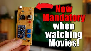
Great circuit. I'm gonna give it a try. How can I get the circuit to respond to a certain frequency so that I can build an array and make a spectrum analyser?
Use filter capacitors and blocking diodes to notch each frequency, Use LM3915s or LM3916s to save space. Chain them to stack 20 or more LEDs in each graph.
honestly, as nice and simple as that code is, it would be rather slow. to keep it using arduino but to get max responsiveness you could use the map routine to 8 and then use that value to drive the pins directly with PORTX... personally I wouldnt even use the arduino tools and would just run raw c with DDRX and PORTX but I'm a masochist.


I took one of the audio jacks off my 8X8X8 LED cube circuit board and put it in a pair of headphones for a coworker. It originally was a hardwired cord that got cut in a car door. My coworker just bought a new M/M phone chord with microphone to plug into the headphones and he couldn't be happier!
You could add an analogue pot to control the sensitivity by scaling your offsets. The Arduino map function is good for that.
Came for the circuit, stayed for the ukulele.
Thanks Karen! As always your projects/tutorials are intriguing. Keep them coming.
Presented in such a fun, smiley manner.
Ha, I never used the notation shown to trigger an led. Another thing learned. thanks Karen.
You could use a timer instead of delay with an interval of 25ms. Leave the mcu to keep cycling round the loop and record the max, mean or average value per timed interval. Reset the value(s) after each interval. Might look a little better.
Nice! Perfect illustration for "killing a fly with a canon".
For me, I would wire the RED LED's into an ESP32 to send commands to the house WiFi so that when the kids got too loud, internet goes down.
Oh haha good idea
You evil genius! 😎🤘
i like your teaching style💯
Amazing, I think if you add a capacitor on each LED you may have some cool fade effects!
but will be costly somehow
the code is using a linear scale to drive the VU meter... its a logarithmic scale for audio.....
Thinking the same thing... I'd go log.
That's why i didn't include LM3914 in my comment.
Yeah Master
Your recompense
Bigger than all
God bless you
Merci
FR.
Thank you!
How can I display my output on screen if I am measuring liquid quantities? Right now I am reading them physically by taking into the bottle
Karen adding to her cool factor again
[puts on sunglasses] Always. 😎
@@maker_karen1785 When you're cool, the sun shines on you 24 hours a day.
Awesome video!! Thanks for uploading it! I don't know why but it bugged me the way "aux" was pronounced. 😆
How do you pronounce it? I said it the same way I’d say auxiliary.
You are talented.
Great circuit. I'm gonna give it a try.
How can I get the circuit to respond to a certain frequency so that I can build an array and make a spectrum analyser?
Use filter capacitors and blocking diodes to notch each frequency, Use LM3915s or LM3916s to save space. Chain them to stack 20 or more LEDs in each graph.
Wow!
Incorporate it into a turbo meter on my sports car. It already has a meter of sorts built in but I would have to stare at the dash to read it.
subtitles would be great
greatings from germany.
Anyone remember Knight Rider? Thinking this could be used to build his (KITT's) voice box display.
I used same one to build controller for chasing strobe lights
Oops! You didn't want scan display on front. Sorry. In that case, read my other post for LM3915 chip.
It would be perfect with more LEDs on a home made DDR machine 😉
Was that a Cartman "here" you said? ;)
Haaaaa cantiiiik
No gloves?
I shoot at my home now where I CONTROL THE THERMOSTAT!! MUAHAHAHA!!
Hi Karen
honestly, as nice and simple as that code is, it would be rather slow. to keep it using arduino but to get max responsiveness you could use the map routine to 8 and then use that value to drive the pins directly with PORTX... personally I wouldnt even use the arduino tools and would just run raw c with DDRX and PORTX but I'm a masochist.
Oh yeah Lady.