first time I really get the meaning and the use of PID, with such Dutch knowledge and know how I was able to grasp the full understanding of the PID. Thank you very much, I will keep my eyes on your videos.
Nice video. I love PID controllers. I know PID theory is literally only the tip of the iceberg with control theory, but it's so useful I think everyone should learn it. Anyways, I made a similar project using my Arduino recently. I didn't use the PID library though, but I've since had a look through the library and it does everything that I did, so its pretty much the same. I modelled mine in the s domain and then converted to z domain using tustin's method as a first order approximation. I know there are better ways out there but this was perfect for me, as I'm only designing a PID controller for a heater. Truth be told I don't actually need a PID controller (proportional would be fine on its own as you wouldn't notice the decaying oscillations) but I just thought it was fun to do. I mapped the transfer functon of the heater also using my arduino, as it's only a first order system I could model it as an exponential equation and then convert it into the s-domain easily. Overall it was a fun project
Hi man, please can you share your work too? I've just learned pid theory and now I want to start putting it on practice with all the concepts of Control course
I have a question, why is the input signal around 75? I though the input could be any value, the setpoint was a fixed value and the output was the one supposed to be as close to 75 as possible
Hi everyone.I want to make line following robot using Arduino.İt is almost finished however ı am stuck with PID tuning.Can You suggest a method which ı can use for PID tuning
First change the values in your input to : Input = map(analogRead(5), 0, 1024, 255, 0); This reverses them again. Then you must adjust the setpoint. In my case (Setpoint = 200;) works well. If it does not work for you, play around until it does. Hint: Do this in an environment with little light.
Duidelijke video! ik zoek een dergelijke oplossing alleen dan op basis van pulsen. Dus wil de pulsen als input gebruiken, kopieeren op een bepaald moment als Setpoint en deze benaderen middels een servo op een klep. Is dit te doen denk je met een arduino?
HI there, nice video i am using your code for a project. however my ouput is working weird. It works only with 0 or 255. My project is a motor going to a target value with a pot value. But the motor is going full power to the target and then backward etc... . Any idea why?
idk why, this code does not work for me at all. I used the same code and same input, but the Output totally shows a different value. It's not stable around 75 at all.
Thank you so much about this video. Could I ask you that what happen if you use another sensor like BH1750. Could you show me how to control the light automatic with Bh1750 by PID
if our value is below the set point it will have maximum brightness but if it is above we have zero brightness , what can we do so it can maintain the value at the set point
Thanks for this video, I required one video clip from you how to control PID based on temperature and setpoint the output should be 0-10VDC is it possible on Aurduino
I can't understand how the library works in coolling. If i set the setpoint 25 (temp) and input = 23 - the output will increase. But if input will be 26 and upper - the output will be 0
You must change the PID settings to reverse for cooling. PID myPID(&Input, &Output, &Setpoint, 2, 5, 1, REVERSE); then the output increases if your input is above the setpoint.
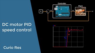
There is a problem with the print statements.... Serial.println(Output); Serial.print(" "); Serial.println(Setpoint); ... there are two "Serial.println" statements. This affects the plot. You only need the last one! The plot then makes a whole lot more sense. As it is... it makes no sense at all.
Dear Sir, Please guide me regarding implementing PID based model using Matlab simulink to code directly in aurduino. And secondly recommend me any tool to fetch data from hardware in real time and analyze its model based result in matlab at the same time
I dunno, that's what I want. I want to create a self balancing robot, it has to work with pid but for input variable we can't pass value of a angle with DC motor. So it has to be stepper or servo motor, if you find a way to get it done with DC motor please help me out.
Quick questions cos I am a new on Arduino. 1- Can you give me a short explanation why do need to map 0, 1024 and 0, 255? 2- how can you get the value to Ki = 10 and the other equal zero? I hope you can give me a every short explanation. Thanks you
@Vannarong Tith, 1- You don't need to map the input from adc range to byte range, if you put the setpoint also in the adc range of the input-pin. The setpoint here is in the byte range of the output, therefore this mapping. Setpoint and input have to be in the same range, output can have another range. (output default 0-255) playground.arduino.cc/Code/PIDLibrarySetOutputLimits
You first know the functions of the PID library then you explain. Incomplete explanation. Sorry to say this but I have to say it. Always think that the person in front of you, don't know anything and teach them from scratch. You did not mention anything what is PID exactly, You did not mention the functions in the program properly, how those functions are working, the calculation behind it. So much to explain. U did a pretty bad job.
In fact al the bs explanation before acc DOING something is what makes this topic a pain in the ass to learn but super fun to do. He did it in a way in which one wants to know more and can do an ejm at home in ten min, get curious and learn with passion, instead of painfully shoving tons of Laplace boring crap on the viewvers. He did a great job and you are the problem
you can calculate it with "PID Tuner" in MatLab. you have first of all to make a step response of LED, then you collect the data, which is (Brightness and time). After that, you import it to "System identification Toolbox"(also in MatLab) to get the transfer function, which will you used in PID Tuner.
Thanks a lot my German friend. Really, appreciated your German English video. I learnt a lot from your good video. Thanks again. best regards gul Rukh Khan grkhan@hec.gov.pk


first time I really get the meaning and the use of PID, with such Dutch knowledge and know how I was able to grasp the full understanding of the PID. Thank you very much, I will keep my eyes on your videos.
Thanks Naboulsi this is perhaps the nicest reaction I have ever had
What a clever way to explain something so difficult! Amazing and well explained! Thank you!
Nice video. I love PID controllers. I know PID theory is literally only the tip of the iceberg with control theory, but it's so useful I think everyone should learn it. Anyways, I made a similar project using my Arduino recently. I didn't use the PID library though, but I've since had a look through the library and it does everything that I did, so its pretty much the same. I modelled mine in the s domain and then converted to z domain using tustin's method as a first order approximation. I know there are better ways out there but this was perfect for me, as I'm only designing a PID controller for a heater. Truth be told I don't actually need a PID controller (proportional would be fine on its own as you wouldn't notice the decaying oscillations) but I just thought it was fun to do. I mapped the transfer functon of the heater also using my arduino, as it's only a first order system I could model it as an exponential equation and then convert it into the s-domain easily. Overall it was a fun project
Hi man, please can you share your work too? I've just learned pid theory and now I want to start putting it on practice with all the concepts of Control course
long time im waiting for this ...my balancing robot will get balance soon ...
did you accomplished
Great video. PID controllers are a very useful tool for automation and control.
Finally, I found a video that shows how to use PID.Thank you.
Thanks Mert, my pleasure
WATCHED 'EM ALL! THANK U
Thanks for the information, I used the code for my project of university :)
But you have Kp and Kd = 0, so P and D are disabled, you only have the integrator correcting for you
Welkom terug logmaker! Thanks for the interesting vid!
I have a question, why is the input signal around 75? I though the input could be any value, the setpoint was a fixed value and the output was the one supposed to be as close to 75 as possible
Aren't most outputs 0-1023 not 0-1024? I'm pretty new to this so could be completely wrong though
Well explained something so complicated.
Thanks a lot , i used this for my college project
Didn’t know pid was this “simple” using Arduino !
this vide teached I How to stduy PID controlled. thank you ! very much.
Great video. PID controllers are a very useful tool for automation and control.
There is video for Arduino to Matlab convert to
Hi everyone.I want to make line following robot using Arduino.İt is almost finished however ı am stuck with PID tuning.Can You suggest a method which ı can use for PID tuning
Excuse me, how can I use this library for a PID controller with inverse action?
i got exactly the same pb. and i Don't have the answer too
First change the values in your input to : Input = map(analogRead(5), 0, 1024, 255, 0);
This reverses them again.
Then you must adjust the setpoint. In my case (Setpoint = 200;) works well. If it does not work for you, play around until it does. Hint: Do this in an environment with little light.
Very good video. I am going to try a loop with pressure transducer and a small pump later today. Thanks!
Duidelijke video! ik zoek een dergelijke oplossing alleen dan op basis van pulsen.
Dus wil de pulsen als input gebruiken, kopieeren op een bepaald moment als Setpoint en deze benaderen middels een servo op een klep. Is dit te doen denk je met een arduino?
This video helped me a lot. Thank You!
can you give inputs on how to implement auto tune feature for the PID?
would be great help if you could...
Why we used Direct in PID declaration
Sehr schön. Danke dir :)
what does the DIRECT keyword in the PID instance mean?
can we use this for self balancing robot.....?
Thanks for the new video. I always learn something new.
my input is PWM (rpm/s), how can i adjust this code ?
Hi. i want auto tune pid. it is imposible? Can you help me
HI there, nice video i am using your code for a project. however my ouput is working weird. It works only with 0 or 255. My project is a motor going to a target value with a pot value. But the motor is going full power to the target and then backward etc... . Any idea why?
does the setpoint 75 mean the value 75 between 0-255 (pwm)?
What software did you use for the Prototyping Board representation at 3:10 ?
probably fritzing
what is the maximum frequency of digital pin3 in this code ???
idk why, this code does not work for me at all. I used the same code and same input, but the Output totally shows a different value. It's not stable around 75 at all.
what should be kp ki kd values?
Isn't it a value between 0 and 1023 for analogRead? 10bits
What do you use for the light sensor? Its a LDR with some kind of amplifier. 0 tot 5volt.
Its this one: www.lightake.com/p/3-Pin-Light-Sensor-Module-for-Arduino-_E8123.html
Which photosensor did u use?
Hey great tutorial! Do you have a link to the photosensor you used in this video?
Thank you so much about this video. Could I ask you that what happen if you use another sensor like BH1750. Could you show me how to control the light automatic with Bh1750 by PID
Can you provide kp ki kd value for setpoint of 0 to 10000
Great vid! Can I change to ultrasonic sensor?
setpoint = 75 a range of values from 0-255 or an actual value?
Depends on what your sensor reads, for example my ultrasonic reads distance so i will use desired distance as setpoint
How do you set up the serial plotter?
if our value is below the set point it will have maximum brightness but if it is above we have zero brightness , what can we do so it can maintain the value at the set point
yeah, i also got like that
can you use the same program with a two pin light sensor?
how to determine Kp, Ki, Kd.
Where can i find that serial plotter of is it a new feature on arduino IDE??
Below the monitor in the menu
Every parameter can cause oscillations if set too high.
Sorry! why 1024? it's not from 0 to 1023?
Can you create pid control with temp sensor a mosfet? Open close ?
very nice explain . could you show me about PID follow line ?
Thanks for this video, I required one video clip from you how to control PID based on temperature and setpoint the output should be 0-10VDC is it possible on Aurduino
I can't understand how the library works in coolling. If i set the setpoint 25 (temp) and input = 23 - the output will increase. But if input will be 26 and upper - the output will be 0
You must change the PID settings to reverse for cooling.
PID myPID(&Input, &Output, &Setpoint, 2, 5, 1, REVERSE);
then the output increases if your input is above the setpoint.
I should point out that this appears to be the opposite of how a PID controller is supposed be set up.
10x very very...….very much. it is helpful for me u saved me!!
There is a problem with the print statements.... Serial.println(Output);
Serial.print(" ");
Serial.println(Setpoint); ... there are two "Serial.println" statements. This affects the plot. You only need the last one! The plot then makes a whole lot more sense. As it is... it makes no sense at all.
Dear Sir, Please guide me regarding implementing PID based model using Matlab simulink to code directly in aurduino. And secondly recommend me any tool to fetch data from hardware in real time and analyze its model based result in matlab at the same time
thank you for sharing your experience
Thanks for what you shared with us it was a very helpful video
Simply explained
Good video...
nice video thanks ,please how i can change the periode of PWM??
And with the PID can you also synchronize dc motor speeds?
I dunno, that's what I want. I want to create a self balancing robot, it has to work with pid but for input variable we can't pass value of a angle with DC motor. So it has to be stepper or servo motor, if you find a way to get it done with DC motor please help me out.
Thank you much!!
that's amazing thank you for doing this
👌
could u please tell me how to install library file
Muito obrigado pelo vídeo! Será útil em um projeto!
Quick questions cos I am a new on Arduino.
1- Can you give me a short explanation why do need to map 0, 1024 and 0, 255?
2- how can you get the value to Ki = 10 and the other equal zero?
I hope you can give me a every short explanation. Thanks you
Look on May Chanel three is a playlist tot Arduino biginners
We need to map those values, because arduino works on atmega chip which can only store those values between 0-255
One more question how can get real PID for my self balancing robot?
@Vannarong Tith, 1- You don't need to map the input from adc range to byte range, if you put the setpoint also in the adc range of the input-pin. The setpoint here is in the byte range of the output, therefore this mapping.
Setpoint and input have to be in the same range, output can have another range. (output default 0-255) playground.arduino.cc/Code/PIDLibrarySetOutputLimits
How to constantly change pid values on arduino uno r3
thank you so much. This is a very useful video
Thank you!!!
i need code for using pressure sensor output to control a steeper motor operated valve through arduino if possible
you can easily find it at GitHub, just google it
Leuke video man
Thanks for explaining. Love your accent btw
I guess it's Russian accent.
@@shreyas7801 it's an extreme Dutch accent
May I ask what your accent is?
Sounds super german but I might be wrong
@@pepinpuercoespin1 it's french
You first know the functions of the PID library then you explain. Incomplete explanation. Sorry to say this but I have to say it. Always think that the person in front of you, don't know anything and teach them from scratch. You did not mention anything what is PID exactly, You did not mention the functions in the program properly, how those functions are working, the calculation behind it. So much to explain. U did a pretty bad job.
In fact al the bs explanation before acc DOING something is what makes this topic a pain in the ass to learn but super fun to do. He did it in a way in which one wants to know more and can do an ejm at home in ten min, get curious and learn with passion, instead of painfully shoving tons of Laplace boring crap on the viewvers. He did a great job and you are the problem
how to calculate Kp,Ki and Kd??????
tuning mate, try and error
Zeigler Nicols criteria
How to calculate these values to control position of a DC motor using rotary encoder
never works lol
you can calculate it with "PID Tuner" in MatLab. you have first of all to make a step response of LED, then you collect the data, which is (Brightness and time). After that, you import it to "System identification Toolbox"(also in MatLab) to get the transfer function, which will you used in PID Tuner.
Very nice
hello my i ask you with email or something ?
Dont eat to mic sir
Thanks
I can barely hear you man... :/
yea good project
can you plzz... show the connection of pid and arduino and sensor
What do you mean? connection? Its all in the library....?
ich liebe dich
Ich liebe dich auch
謝謝
Thanks a lot my German friend. Really, appreciated your German English video. I learnt a lot from your good video.
Thanks again.
best regards
gul Rukh Khan
grkhan@hec.gov.pk
he sounds dutch
clearly a Dutch guy!
Which photosensor did you use???..
Ds 1307