I have been using these frequency dividers in my microcontroller-based projects for almost a year for different purposes but until now I didn't know how it was possible to "divide" a clock frequency, it just makes no sense when you look at it that way, but the picture depicting this "division" actually explained it perfectly, all you do is increase the T by the amount of N you want. I still don't know how these digital blocks actually work but at least I know how they change frequencies
In one of the above video you said for delay we have to use dual edge triggered flip flops but in this video u are using either posedge or negedge ff for delay .. why?
D flip flop will add 1 clock cycle delay whether its posedge or negedge triggered. Can you please elaborate more how have you generated q2 from q1 in f/3 problem?
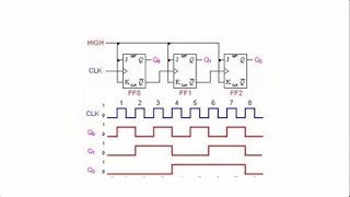
As we notice that in mod 7 counter, States are 000 001 010 011 100 101 110 If we take Q1, it's changing from 0 to 1 or 1 to 0 right after 2 clock pulses That is, the frequency of Q1 is f/4
There is a mistake in you timing diagram of Q3 at 16:30. The pulse for Q3 at the end of the timing diagram is wrongly delayed by half clock cycle instead of 1 full clock cycle.
for frequency divide by 3 ckt you have taken Q1 and did shifting for the wave generated through d-ff and did or we got output at 3-4.5(On)cycle and 4.5-6(off)cycle. why dont we take Q0 as both have 33.3% duty_cycle? is there any reason taking only Q1?why?
Hello Ajay, sorry for the delayed response .. I am sending you a snapshot, Q is missing in it .. Can you please draw it?? I am trying to give you an answer to your question. drive.google.com/file/d/1Os9bVzfb8K_HrcnSjsCCRO4BKxXvHh4k/view?usp=sharing
hello, i try by myself to create the f/7 as you shown in the video but there's a problem becase the last falling edge given exsta half clock cycle at '1'. and i am not get 50%. thank you very much for your video!
@@TechnicalBytes Hi i got the same result , for divide by 7 , if we delay the msb by 0.5 cycle and or it with non delayed version , the final result is -> on period = 4 cycles and off period = 3 cycles and failing to meet 50% duty cycle, could you help here ?
Excellent explanations. How to get access to a video on divide by fractional number. It says to join the channel but no explanation what this means. Thanks
Actually, some of the videos are not publicly available. Those are available to members only. if you want to become a member, then press on the 'JOIN' button near subscribe button.
you can press on the following link to join the channel: ua-cam.com/channels/niC9ol6QzUH0pVQ3sSfiIQ.htmljoin There are two types of memberships, you can join the basic one to get access all the exclusive videos.
This channel is dedicated to a person like you only.. I am going to put huge material on this channel .. But due to my hectic schedule, i am going bit slow.
Dear u dont know u just amazing your questions level n your tricky approach amazing i just love it i believe in realization techniques in digital design
Hi...very good explanation. I have a question. You were used MOD-N counter in frequency division. As per my knowledge MOD-N counter can implement in synchronous and asynchronous manner also, so which counter it is, synchronous or asynchronous ?
The fact that negative edge trig d flop will delay by half cycle is only true if the counter is made of positive edge triggered flip flops. They have to basically be opposite triggering for half cycle delay and same triggering for 1 cycle delay.
In MOD 7 counter u said we can't use Q1 because it's frequency is not f/7 .. .but why did u use q1 in f/5 counter ...in that case also it doesn't have frequency f/5 ....because only MSB can have f/mod no.
Dear, Q1 is not even a periodic signal .. It is 0 0 1 1 0 0 1 .. It can not be a clock signal. Just repeat this sequence .. 0 0 1 1 0 0 1 . 0 0 1 1 0 0 1 See it is not a clock signal..So, can not take it..
Hi...great video! Have a question. Can we generalize the number of flip flops required in any frequency divider? We see that for a f/n divider we need a Mod-n counter which will tell us the number of FFs required according to the bits. But depending upon the number of altering clock cycles, we have to add another FF. So pls suggest if any way to find this.
Yes you can! but I am not sure for what purpose, you want to do so .. but let me tell you the answer .. Step1: Just count the number of 0's and 1's in the MSB bit of MOD N counter .. Step2: Get the difference between number of 1's and 0's Step3: divide this difference by 2.. if division is 0, means no flop required. if division is 1, it means 1 posedge flop required. if division is 1.5, it means 1 posedge FF and 1 negedge FF if division is 2, it means 2 posedge FF required. if division is 2.5, it means 2 posedge and 1 Negedge FF ------------------------------------------------------------------------------- -------------------------------------------------------------------------so on.
For frequency division by integer, couldn't you use a decade counter (4017 for example) and simply take the appropriate output into the reset pin? My mod 7 circuit, which lights the segments of a 7-segment display sequentially, and the dp as the input clock indicator, has the q7 pin (output 8) connected to pin 15 (reset).
Sir, you are very correct, we can use Decade counter to divide a frequency but duty cycle will not be 50%. As IC 4071 gives one hot encoded output. It is very easy to convert a one hot counter to clock frequency divider .. Please go through my previous video: ua-cam.com/video/AfINILc0WEg/v-deo.html
Thankyou for the wonderful explanation as always. How would we tackle a situation when the DC produced by the frequency divider is for example say 75% but we want 50% duty cycle? what do we do then? You have addressed the situation where the desired DC is more than the actual DC so we can add flops to achieve that, how do we do it for the example that I mentioned? TIA :)
I am not sure but in that case we can use d flip flop ( negative or positive depending on our requirement) and then will use and gate or some others gates depending on the output we need like xor etc. Thanks
How does the f/4 clock divider avoid having a glitch in the center as you transition from counter values 2'b10 -> 2'b11? The others work because the use of the inverted clock being used to create a delayed version that are OR'd together, which helps protect from any potential glitch in the middle.
you dont need a mod-n couter for 2^n divisions. f/2 is a single d-ff which has its q' connected back into itself and thus output q serves as an f/2 clock. connect this f/2 clock to the clock input of another d-ff which has its input from it's q' as well. thus the output of d-ff q2 serves as an f/4 clock. you can keep cascading connections to get f/(2^n) divisions.
8:50 sorry but I can't understand why Q1 is a signal of frequency f/5? Also 11:42 why Q1 is not a signal of f/7? I thought you could optimize the last case by choosing the Q1 column which had 3 high signals and 4 low signals
Observe Q1 carefully, It is 0 0 1 1 0 0 1 Let us repeat this pattern 0 0 1 1 0 0 1 0 0 1 1 0 0 1 0 0 1 1 0 0 1 0 0 1 1 0 0 1 ........ See Q1 carefully .. It is not even a clock signal .. because logic HIGH and logic LOW times are not fixed .. That is another reason for not considering Q1.. Let me know if you need further clarification..
Divide by 6 is very easy divider, because a simple TFF-trigger is enough to divide by 2, next step is by 3 divider (2*3=6), which can be implemented with simple counter. One of the reason of video, I presume, is to make combinational frequency divider, but if divider is multiple of 2 we can do that with synchronous logic.
In f/5 case .. We are using Mod 5 counter which keep on running .. Q1 will be 0 0 1 1 0 As counter keep on running .. so let us repeat this sequence .. 0 0 1 1 0 _ 0 0 1 1 0 _ 0 0 1 1 0 _ 0 0 1 1 0 ........... Just observe this sequence .. it is a train of 2 1's and 3 0's, which means five bits forming a clock. hence it is f/5 Let me know if you need any further clarification.
Yes, definitely .. It is simplest, just try once .. if possible, please draw it on page, take a snapshot, store in gdrive and share it here for others ..
Hi, Actually exact MOD N counter video is not created yet .. soon , we will create it and share its link .. And we appreciate your suggestion that we must put corresponding links in the description section.. we will follow it definitely ..
that means you simply need to divide your input frequency by 12.5.. please refer below mentioned video link to get your answer, let me know if you are able to synthesize your design. ua-cam.com/video/TgsyQgliuYc/v-deo.html


![Clock divided by 3 || Explained step by step! [Frequency divide by 3 ] F/3 or F/odd number](http://i.ytimg.com/vi/wxUqxSE_F5A/mqdefault.jpg)


This was the most general approach i have seen to make clock dividers! this was great!
Thanks and glad that you liked this video !!
Thank you for such clear explanation with examples!
You're very welcome!
great video thank you
I have been using these frequency dividers in my microcontroller-based projects for almost a year for different purposes but until now I didn't know how it was possible to "divide" a clock frequency, it just makes no sense when you look at it that way, but the picture depicting this "division" actually explained it perfectly, all you do is increase the T by the amount of N you want. I still don't know how these digital blocks actually work but at least I know how they change frequencies
🥰🥰🥰🥰🥰
seen many videos, but this one actually helped.
Thanks for your compliment .. We are going to create a video on clock divider for fractional numbers soon.
Thank you so much It was very helpful.
Very glad to know that this information is helping .. thanks for sharing your views !!
good video, helped saumya and me!
Thanks , please keep giving your feedback on other videos as well. your likes and dislikes
This channel is going to obtain great viewership, I can say that for sure
Hope so! Thank you
Where is the video for Mod N Counter?
Sir
It is fantastic useful clarification like us.
Thaks.
Gopal raju
Thanks and welcome
Concepts are very informative and simple to understand...thanks
Thanks for your complement..
Thanks for your effort !
My pleasure!
Your channel had amazing informative content. Thanks🙂
Glad it was helpful!
Good way to explain concepts easily
Thanks
Very nice
Thanks !!
Very nice explanation
Thanks!!!!!
thank you bhaiya much appreciated
Thanks , please keep giving your feedback on other videos as well. your likes and dislikes
In one of the above video you said for delay we have to use dual edge triggered flip flops but in this video u are using either posedge or negedge ff for delay .. why?
Beautiful lecture.
Glad you liked it
This is a great explanation! Thanks You !!
You are welcome!
how negative edge trigger flip flop delays the input by half clock cycle??
Infact it will delay by 1 clock cycle if we are using simple flip-flop
great explanation sir
Thanks and welcome
Excellent tutorial sir....
Many many thanks
Best video 👏🎉 incredibly incredible 😁
Wow, thanks!
isnt q1 f/7 only? I think it will be tough to make it clock of 50% .....but q1 is periodic
what an amazing explaination !!!!!!!!!!!!!!!!!!!!!
Glad to know that you liked this video ..
Sir you explained it with such a beautiful manner but please if possible allow the access of your next video.
Sorry dear, it is our channel policy !!
super sir
Thanks and welcome!!
Very useful. thank you
Glad it was helpful!
best video
Thanks !!
Very good explaination
Thanks !!
at 11:42nd min how you decided that Q1 columns freq is not f/7? for f/7 counter also could you please add the video of Mod N counter
D flip flop will add 1 clock cycle delay whether its posedge or negedge triggered. Can you please elaborate more how have you generated q2 from q1 in f/3 problem?
please make some intersting tricky vede on basic digital electronics
Sure .. I have created many .. please go through them as well .. share your valuable feedback also..
hi,negative edge trigger flip flop fwd alters by half cycle, for n/7 example: q2 which is low for 4 cycle will become low for 4.5 cycle ..
Sir., Please upload videos on 30% and 70% duty cycle... Thank you so much
Please go through the following video:
ua-cam.com/video/AfINILc0WEg/v-deo.html
hi sir can you explain frequency multiplier
In f/6 why don't we just use q0 to take out the frequency of f/6? then we won't be needing extra hardware for that circuit. Anyone can explain that?
q0 is a div by 2
it goes like this 010101
but a div by 6 goes like this 000111
Sir, I have a doubt. We are using or gate so it will introduce its own delay practically. So how to we get rid of these issues?Kindly reply sir
Sir, what do you mean by q1 is not having a signal f/7?
Please explain
As we notice that in mod 7 counter,
States are
000
001
010
011
100
101
110
If we take Q1, it's changing from 0 to 1 or 1 to 0 right after 2 clock pulses
That is, the frequency of Q1 is f/4
Hi if we incorporate the value of the CP to Q delay of the added flip flop after the mod N counter, will that still give us the desired result?
There is a mistake in you timing diagram of Q3 at 16:30. The pulse for Q3 at the end of the timing diagram is wrongly delayed by half clock cycle instead of 1 full clock cycle.
nice
Thanks!
for frequency divide by 3 ckt you have taken Q1 and did shifting for the wave generated through d-ff and did or we got output at 3-4.5(On)cycle and 4.5-6(off)cycle. why dont we take Q0 as both have 33.3% duty_cycle? is there any reason taking only Q1?why?
How can positive edge triggered d flipflop delays the output by 1 cycle...it remains same.
Hello Ajay, sorry for the delayed response ..
I am sending you a snapshot, Q is missing in it .. Can you please draw it?? I am trying to give you an answer to your question.
drive.google.com/file/d/1Os9bVzfb8K_HrcnSjsCCRO4BKxXvHh4k/view?usp=sharing
please draw on a notepad, and send it to me..
Sir why we can't use q1 input in f/7 frequency divider as it is also a signal of f /7.
Any reason for this???
hello, i try by myself to create the f/7 as you shown in the video but there's a problem becase the last falling edge given exsta half clock cycle at '1'. and i am not get 50%. thank you very much for your video!
Can you please share your waveform with me??
@@TechnicalBytes Hi i got the same result , for divide by 7 , if we delay the msb by 0.5 cycle and or it with non delayed version , the final result is -> on period = 4 cycles and off period = 3 cycles and failing to meet 50% duty cycle, could you help here ?
Excellent explanations. How to get access to a video on divide by fractional number. It says to join the channel but no explanation what this means. Thanks
Actually, some of the videos are not publicly available. Those are available to members only.
if you want to become a member, then press on the 'JOIN' button near subscribe button.
you can press on the following link to join the channel:
ua-cam.com/channels/niC9ol6QzUH0pVQ3sSfiIQ.htmljoin
There are two types of memberships, you can join the basic one to get access all the exclusive videos.
sir please upload the video for frequency division by decimal no.. thank you
Thanks for showing your interest in our channel..Sure, we will try to make a video of your choice
Hello Mr. Shashikant, We have uploaded the requested video. use the following link to access it.
ua-cam.com/video/TgsyQgliuYc/v-deo.html
Please explain how did u created divide by 3 circuit first.
just wow great amzing
Thanks dear Deepak for your awesome and inspirational words ..
@@TechnicalBytes Sir i want more digital question with tricks pls sir
This channel is dedicated to a person like you only.. I am going to put huge material on this channel .. But due to my hectic schedule, i am going bit slow.
@@TechnicalBytes ok sir got it dear if you have some interview as in word or ppt form can u pls send me deepakk.alpine@gmail.com
Dear u dont know u just amazing your questions level n your tricky approach amazing i just love it i believe in realization techniques in digital design
Hi...very good explanation. I have a question. You were used MOD-N counter in frequency division. As per my knowledge MOD-N counter can implement in synchronous and asynchronous manner also, so which counter it is, synchronous or asynchronous ?
In usual practice, synchronous designs are used .. because asynchronous designs are prone to glitches.
Synchronous because at the outut of each ff f'= f/n
great video, sir how do i make f/4 with 25% duty cycle?
How can we understand freequncy from truth table?
Sir l have one doubt why there is no change in q3 at clock no 5 posedge edge??
The fact that negative edge trig d flop will delay by half cycle is only true if the counter is made of positive edge triggered flip flops. They have to basically be opposite triggering for half cycle delay and same triggering for 1 cycle delay.
i also have same question
Hai sir i want to known about the mod -n counter could u please provide the link, sir please .
In MOD 7 counter u said we can't use Q1 because it's frequency is not f/7 ..
.but why did u use q1 in f/5 counter ...in that case also it doesn't have frequency f/5 ....because only MSB can have f/mod no.
Hi, how can we decide that output Q1 is not a signal with frequency f/7 ?
Dear, Q1 is not even a periodic signal .. It is 0 0 1 1 0 0 1 ..
It can not be a clock signal.
Just repeat this sequence ..
0 0 1 1 0 0 1 . 0 0 1 1 0 0 1
See it is not a clock signal..So, can not take it..
8:50 Q1 is not f/5 it is f/4
how to design a circuit with duty cycle of 1/3 using D FF's??
Hi...great video! Have a question. Can we generalize the number of flip flops required in any frequency divider? We see that for a f/n divider we need a Mod-n counter which will tell us the number of FFs required according to the bits. But depending upon the number of altering clock cycles, we have to add another FF. So pls suggest if any way to find this.
Yes you can! but I am not sure for what purpose, you want to do so .. but let me tell you the answer ..
Step1: Just count the number of 0's and 1's in the MSB bit of MOD N counter ..
Step2: Get the difference between number of 1's and 0's
Step3: divide this difference by 2..
if division is 0, means no flop required.
if division is 1, it means 1 posedge flop required.
if division is 1.5, it means 1 posedge FF and 1 negedge FF
if division is 2, it means 2 posedge FF required.
if division is 2.5, it means 2 posedge and 1 Negedge FF
-------------------------------------------------------------------------------
-------------------------------------------------------------------------so on.
Take n/2 flip flop as we are making johnson counter.
Hi, This video is great. Can you help me to build a frequency divider (f/n; n is odd) with 75% duty cycle?
Excuse me. I have problem. Why we get attention to Q1 in f/5 instead of Q2?
For frequency division by integer, couldn't you use a decade counter (4017 for example) and simply take the appropriate output into the reset pin? My mod 7 circuit, which lights the segments of a 7-segment display sequentially, and the dp as the input clock indicator, has the q7 pin (output 8) connected to pin 15 (reset).
Thanks for showing your interest in Technical Bytes
Sir, you are very correct, we can use Decade counter to divide a frequency but duty cycle will not be 50%.
As IC 4071 gives one hot encoded output. It is very easy to convert a one hot counter to clock frequency divider .. Please go through my previous video: ua-cam.com/video/AfINILc0WEg/v-deo.html
Thankyou for the wonderful explanation as always.
How would we tackle a situation when the DC produced by the frequency divider is for example say 75% but we want 50% duty cycle? what do we do then? You have addressed the situation where the desired DC is more than the actual DC so we can add flops to achieve that, how do we do it for the example that I mentioned? TIA :)
I am not sure but in that case we can use d flip flop ( negative or positive depending on our requirement) and then will use and gate or some others gates depending on the output we need like xor etc.
Thanks
It was a great video. Pls also upload the video of frequency divide by 1.5 counter.
Thanks for your complements .. we will try to put requested video on priority
Hello Mr. Chandra, We have uploaded the requested video. use the following link to access it.
ua-cam.com/video/TgsyQgliuYc/v-deo.html
How does the f/4 clock divider avoid having a glitch in the center as you transition from counter values 2'b10 -> 2'b11? The others work because the use of the inverted clock being used to create a delayed version that are OR'd together, which helps protect from any potential glitch in the middle.
you dont need a mod-n couter for 2^n divisions. f/2 is a single d-ff which has its q' connected back into itself and thus output q serves as an f/2 clock. connect this f/2 clock to the clock input of another d-ff which has its input from it's q' as well. thus the output of d-ff q2 serves as an f/4 clock. you can keep cascading connections to get f/(2^n) divisions.
@11:48 Q1 is not having frequency which is equal to f/7. So, How to identify which one(Q1,Q2) will have freq f= f/7 .
like content
Thanks !!!!!
How can we get Q2 waveform here
8:50 sorry but I can't understand why Q1 is a signal of frequency f/5? Also 11:42 why Q1 is not a signal of f/7? I thought you could optimize the last case by choosing the Q1 column which had 3 high signals and 4 low signals
HOW Q1 IN CASE OF FREQUENCY DIVIDER FOR F/7 IS NOT HAVING FREQUENCY F/N?
Same doubt
I have a doubt, how do you get to know that Q1 is not a signal having frequency f/7??
Observe Q1 carefully, It is 0 0 1 1 0 0 1
Let us repeat this pattern
0 0 1 1 0 0 1 0 0 1 1 0 0 1 0 0 1 1 0 0 1 0 0 1 1 0 0 1 ........
See Q1 carefully .. It is not even a clock signal ..
because logic HIGH and logic LOW times are not fixed ..
That is another reason for not considering Q1..
Let me know if you need further clarification..
@@TechnicalBytes Hi sir, please further clarify the same question.
Cant we design a f/6 using a and gate with q1.q0 and ORing it with q2. ((Q0.Q1)+Q2)
Divide by 6 is very easy divider, because a simple TFF-trigger is enough to divide by 2, next step is by 3 divider (2*3=6), which can be implemented with simple counter.
One of the reason of video, I presume, is to make combinational frequency divider, but if divider is multiple of 2 we can do that with synchronous logic.
How Q1 has same frequency as Q2 in freq/5 case?
In f/5 case .. We are using Mod 5 counter which keep on running ..
Q1 will be 0 0 1 1 0
As counter keep on running .. so let us repeat this sequence ..
0 0 1 1 0 _ 0 0 1 1 0 _ 0 0 1 1 0 _ 0 0 1 1 0 ...........
Just observe this sequence .. it is a train of 2 1's and 3 0's, which means five bits forming a clock. hence it is f/5
Let me know if you need any further clarification.
sir can we use this method for f/16 too?
Yes, definitely .. It is simplest, just try once .. if possible, please draw it on page, take a snapshot, store in gdrive and share it here for others ..
If you still face issues, then I will share it for you
can you please upload mod n counter.
silly question but, how would we get the frequency to f/12 using 1 4bit counter (with clear input)?
take a mod 16 counter ( 4 f/f) clear all fliplops when count reaches 1100. do this using and gate. Qd.Qc.Qb'.Qa' = clear
@11:26 how can we say that the frequency of bit Q1 is not f/7 ? can you please explain
Because Q1 is completing it's single cycle in 4 clock pulse not 7 .
Sir please upload video for frequency division by decimal
Firstly, thanks for showing your interest in our channel .. we will try to put this video on priority, as many subscribers are requesting..
Hello Mr. Sudhir, We have uploaded the requested video. use the following link to access it.
ua-cam.com/video/TgsyQgliuYc/v-deo.html
Sir , How to decrease the duty cycle. For example from 50% to 25%.
Hello Rohan, Please go through the following video, perhaps it will clarify in more detail:
ua-cam.com/video/AfINILc0WEg/v-deo.html
Let me know if it served your purpose..
I didn’t getting modN counter video link .. can u share here..?
I think it’s better to share related links in description than video right corner.
Hi, Actually exact MOD N counter video is not created yet .. soon , we will create it and share its link .. And we appreciate your suggestion that we must put corresponding links in the description section.. we will follow it definitely ..
Technical Bytes thank you 😊
@@TechnicalBytes Hi, Is the mod N counter Video ready?
I have paid money for membership but I can't able to see videos..
are you not able to see any of the members video?
@@TechnicalBytesNow I can see
Can you tell me kindly how can I convert 1 Ghz frequency to 80 Mhz frequency?
that means you simply need to divide your input frequency by 12.5.. please refer below mentioned video link to get your answer, let me know if you are able to synthesize your design.
ua-cam.com/video/TgsyQgliuYc/v-deo.html
Still frequency divider by decimal is not uploaded...u said it is in priority....many other videos came...still waiting for that..🙂😭
Sure Ujjwal .. I will do it at priority now ..
Hello Mr. Chandra, We have uploaded the requested video. use the following link to access it.
ua-cam.com/video/TgsyQgliuYc/v-deo.html
Bhai kmap bhi karna hai isme to meri teacher ne number nahi diye kya kar diya ye
ohh,, realyy :)
Very nice
Thanks
Very nice
Thanks
Very nice
Thank you!