POLICE LED Light DIY with NE555 - PCB Tutorial

Вставка
- Опубліковано 23 лип 2024
- ► $2 for 2-Layer PCBs & $7 for 4-Layer PCBs: jlcpcb.com
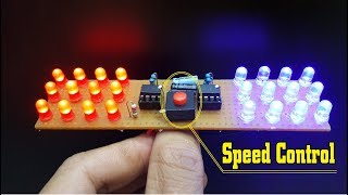
In this video we see a simple circuit, based on two NE555 that is able to reproduce the effect of the lights of the Police Cars, all made on a fantastic Black PCB.
After trying the excellent service offered by JLCPCB I recommend it, the quality of the PCB is high, customer service is always available and professional, the time of realization is short and the delivery of PCBs is by express courier. JLCPCB is a great place to get hight quality custom circuit boards at an extremely low price, you can buy 5 PCB Boards (Any Color) for 2$ !!!
Components:
- 2x NE555 [ bit.ly/2QTemmJ ]
- 20x LEDs 5mm [ bit.ly/2UzRDgR ]
- 2x 850 KΩ Resistors [ bit.ly/2ytgn3e ]
- 1x 1uF Electrolytic Capacitor* [ bit.ly/2WlIgCt ]
- 1x 100nF Polyester Capacitor [ bit.ly/30xHDbJ ]
- Heatsink: [ bit.ly/30mKYdR ]
- 9V Battery Clip [ bit.ly/2SrU0Sd ]
- PCB: (Ready for jlcpcb.com): bit.ly/3jwpeU7
*Don't use my PCB for profit or sponsored videos.
Power with 9V DC and use 25/50/100V Electrolytic Capacitor
For any other questions you can ask in the video comments:)
EXTRA (this light with Orange LED): • Orange LED Flashing Li...
Chapters:
0:00 - Intro
0:40 - Project Explanation
1:55 - Gerber Upload
2:27 - Unboxing e Gadget
3:33 - Start Assembly
5:52 - TEST
7:34 - END
■▬▬▬▬▬ LINK & Support ▬▬▬▬▬■
✅ UA-cam: / stefano91ste
✅ Instagram: / stefano91ste
✅ Pinterest: www.pinterest.it/Stefano91ste
✅ My STORE: / stefano91ste
Watch another video =)
● Music Keyboard: • Music Keyboard with NE...
● LED Water Level: • LED Water Level indica...
● Police Light: • POLICE LED Light DIY w...
● Vu-Meter Stereo: • Vu-Meter Stereo -20 +3...
● Traffic Light: • Make your own Traffic ...
● Vu-Meter 40 LED: • Vu-Meter 40 LED on PCB...
● Voltage Detector: • AC Voltage Detector DI...
WARNING: This video is only for demonstration. I don't take any responsibility.
#NE555 #Police #Flasher - Наука та технологія


Very very nice, I just ordered, let us wait and see what happen. Many thanks for sharing PCB file!!!!!
Thank you :)
So simple and cool!!
Thank you!
Great quality work
awesome video, thanks for sharing, great!!! Happy day!
Thank you =)
3:27 Very nice pcbs. Good sized annular holes and boards are nice n thick.
🤔👍🏻
Complimenti fai dei bellissimi progetti
Grazie mille =)
Nice, my use is two halve pcb's with orange flash lights on both side for turnflash on my old (40 years) motorbike for turning left and right
Interesting, soon I will try the version with orange led of this circuit, in "man at work" style
Awesome!😎
Hi Stefano91ste! This is exactly what I was looking for, however I would like to run a total of 12*3mm LED (6*Red and 6*Red) from a 7.4v 10400mHA Li-Po battery (RC Car) what would I need to change on this to make it work?
Tripple 5 IC is one versatile chip. We can do infinite number of cool projects using this IC.
it is one of the best, at school the teacher told us that there is almost a 555 in every circuit XD
@@Stefano91ste during my bachelor's degree in engineering we used the triple-5 quite often. I myself used it to build many projects.
May I ask you if you have already any kind a christmas three in PCB or any temperature measurement by led?
Of course I have them, here they are:
- Christmas tree Vu-Meter (PCB): ua-cam.com/video/Si97iS8ZC9g/v-deo.html
- LED Thermometer (PCB): ua-cam.com/video/cBxRSFctnm8/v-deo.html
- Christmas tree DIY KIT: ua-cam.com/video/lrkmMVbI10w/v-deo.html
Here all my PCB projects: ua-cam.com/play/PL__2OB3tNsdSXa2StOpOCny1JgMIXf9t3.html
Muy bueno el proyecto 👌👌
Gracias =)
Super project
Thank you =)
How can I order for this prepared pack because I do not have facility or access to Garba files. I need to build this project soon
Great project! How would you get the flashes to overlap on each side? To explain better = red flash overlaps blue flash by a few milliseconds. Thanks!😁
Thanks to you😁
It's really beautiful 😁😁👍👍👍👍
Thank you =)
@@Stefano91ste I'll follow your channel, I was liked the perfectionism of your jobs. 👍👍👍
Thank you and thank you for appreciating my work =)
Thanks for sharing buddy! Awesome work!
Thank you for appreciate my work!
Very good, awesome 😉👍🇧🇷🇧🇷👏👏👏👏👏👏👏
Thank you again😎
Very very nice
Thank you :)
Greetings. For 5v,how i have to do? Thanks
Very good
Thank you!
can you change how it strobes ?
Are these boards available to buy without LEDS installed ? I am not looking to do programming myself. If they can be purchased already programmed can someone contact me. Thank you
Nice
Good! 💪
Thank you!;)
Nice circuit. Can you explain how it works? Those resistors create RC circuits to charge capacitors in specific time?
Thanks! the capacitors are responsible for regulating the flashing frequency of the LEDs and the exchange rate between the red and blue LEDs, and thanks to this configuration with the two NE555s I can switch the flashing frequency of the LEDs between the two groups
What if I want to use high power LED COB instead? Can I use two mosfets on the output of the ICs?
Yes, you can, you can also connect relays.. consider that each NE555 can give you a maximum output of 200mA
Hi, what if we want a different number of leds? can we just solder more/less than 20?
20 is the maximum, to further increase them you need to redesign the circuit by adding transistors
Can I use only 1 bicolor led?
This project is amaizing. Can I order for this stuff to build and solder the circuit myself?
Hy, you can only buy my PCB from JLCPCB, download my gerber file and upload it on jlcpcb.com
What is the voltage range with which this design can be used . Thanks for this fun project
Hi, use 7 to 12v DC for best performance, it also works at 5 volts but the brightness is low
What is that yellow item on your circuit ?
can i also use a 680k resistor
Super 👍
Thank you :)
Good Jobs 👍🏼
... Hobi Elektronika Coming 😊
Thank you!
Gave up @ 3:03. I didn't tune in to watch a commercial. But thank you for your efforts. Won't be comming back.
Sorry you don't understand, you can skip the part of the video where I talk about the sponsor without any problems. The circuit diagram and PCB remain available even for those who don't watch it or the full video... but remember that it was thanks to that sponsor that I was able to share, for free, several dozen fun PCB projects to assemble.
Why the use of 100v 1uf capacitor on a 9v power supply ? Great video and thank you I have received your boards look great
Hi, thanks! I have many 100V available, so I use those. Hope you enjoy with this PCB :)
Love all your vids
If I use 12vdc source and for powering 12vdc 5watt led what should I change sir?
For the 12V it is fine without modifications. 5W LEDs cannot be used because each NE555 can deliver a maximum of 200mA, you should use power transistors and the circuit should be completely redone.
Please make a temperature control switch with lm358
Good idea!
Hey, nice video and cool lights!
Thank you😎
with VR will be great to change the velocity the flashing led
True, but I would not have been able to put it while keeping this fine PCB design, I will use a potentiometer in a more advanced version of this project
Hi there... I tested this out on my every circuit software. I did exactly the wiring routing correctly. I did not hook the number 4 to 8 yet just to see if it works... when I turn it in. The timer greyed out. This mean there's no going in the number 4 pin. I don't understand why it works in your video... the software requires you to hook the number 4 pin with number 8 together then it will power on. This is so weired..weird... I guess I gonna have to try another app on my phone. The light did not come on... I don't know what is up to with it...
Hi, the circuit works as designed, try to connect PIN4 to VCC on your software, but in the lab you do exactly as in my schematic;)
hi E P S...
'
that coool nice pretty LED flash kit / project
Like 1.2K❤ 😉👍🇧🇷🇧🇷 big job 👏👏👏👏
Thank you😁
Nice police light can u make a solar panel charger for me 😍😁
Gee your police lights are so neat compared to mine. Stefan you're a perfectionist! I like your videos. You put a lot of effort into creating good content. Keep up the good work.👍🏻
Thank you so much for appreciating my work on UA-cam =)
@@Stefano91ste Your welcome. My own content is crude and unprofessional in comparison. 😂😆
Wow nise board for water level. How I can download your gerber file?
Hi, in video description of any PCB video you can find links for gerber files
Hi Stefano this proyect working wit 12v?
Hi, yes it work also with 12 Volt DC, but not more than 12 Volt
@@Stefano91ste gracias Stefano
Please, I need a design as a file.
Am also an electrician and I need five pieces of this pcb to sponsor diy projects on you tube how can I get this suplly
Hi, you need to post videos on UA-cam that people like and get subscribers to the channel. When you have reached a good number of subscribers, the sponsors will look for you😁
I’m not able to download the PCB that’s ready to send to jlcpcb.com. Can you help me with that?
Hi, yes of course!
1) Download the .rar file from this link: bit.ly/3jwpeU7 (it's the same link I shared in the video description)
2) Do not unzip the file, it is ready as it is.
3) Go to jlcpcb.com and create an account if you don't have one.
4) Click on "QUOTE NOW" and upload my file on the next page.
5) Follow my video from 1:55 to see the whole upload process.
6) You can choose the color you want for the PCBs, it doesn't change the cost. Then choose a shipping method, indicate a shipping address and a payment method.
Bueno...con un 555 nomas podes hacer lo mismo y un transistor de driver para no forzar la salida del 555 x eso necesitas disipador ✋🏻
- Bien, tal vez pronto haga una versión con transistores, pero con más de 50 LED para cada canal.
- Right, maybe soon I'll do a version with transistors, but with 50+ LEDs for each channel
I built the circuit according to the schematic, using 4 LEDs on each side. The LED's do a "blink-blink" at the same time on both sides, not alternatively!!! I checked the circuit many times. Are you sure the schematic is correct?
Hi, I am very sure of the correctness of my schematic, you can also check the connections from the PCB drawing.
@@Stefano91ste Found my problem. The LEDs on each side were in the same direction. This actually is not a bad circuit. This way, both sides do a blink-blink at the same time, which could serve as a double-warning set of lights. Yours is much cooler, though :) Thank you very much for your reply and this awesome circuit! Wish you great health and happy tinkering with ideas.
@@Stefano91ste Found my problem! The LEDs on both sides were in the same direction. This actually is not bad circuit. In this case both sets of LEDs do a "blink-blink" at the same time, which could serve as a double-warning signal. Yours is much cooler though! :) Thank you for your reply. Wish you great health and happy tinkering with new ideas.
Good good
Thank you!
Nice o e!
Thanks:)
No pude hacer un pedido la tutoría no está claro es muy confuso necesito 8 tableros
8 cards cannot be ordered, from 5 to 10 and multiples.
No se pueden pedir 8 tableros, de 5 a 10 y múltiplos
How to make it work with 12 v for car and make it fast lot slow
Hi, it is actually ready to work at 12V - towards the end of the video I explain that to use it in the car with 12 / 14V and for long periods it is necessary to add a heatsink to the two NE555 ICs.. however using it in the car on the road is illegal, know it and do it at your own risk
@@Stefano91ste thank you. I am not planning to put on car , just wanted to make it work on 12v
I need this PCB and please tell me the price
Hi, i have shared the PCB file in video description
احسنت عمل جيد استمر به
R is 820k not 850k??
hi E P S...
'
5 flashers on blue LEDs = 5 flashers on red LEDs...
try add speeding control adjustment from fast flash to slow flash
i will with next version =)
Tôi muốn nó chạy bằng nguồn 5v DC
Decoupling capacitors on power supply...!
Missing...
Which power supply are you talking about?
Hello sir
sir please help me my red led is not blinking but blue led is perfectly blinking please help me sir 🙏 please reply me sir 🙏
Please reply sir 🙏
Hi, If the components have been salted correctly, it is likely that one of the two NE555s is faulty.
Where is Gerber file
there is a link in the video description, just after the list of components.
सर ये सर्किट मैंने बनाया लेकिन पोलीस लाइट मोड कूच डर चालणे के बाद रेड LED 3 बार blink होती है लेकिन ब्लू led 1 हि बार blink होती है ऐसा क्यू क्या इस सर्किट को रिसेट करना होता है तो कैसे करें प्लिज बताइये।
English please
555 is my favorite!
Motorcycle police should attach these to their helmets. 😆
May I make a small request? Could you maybe do more 5v designs? Almost all the things I make use 5v so they can be powered using a USB power bank. Just makes things a little more convenient. :)
Hi, true! - about 5V I should try, but it's not always possible, it mostly depends on the components I use :)
How to use with 4v battery
Hi, 4V is low, at least 6V would be needed.. however you could mount a joule thief between the battery and the flashing light .. it should work
@@Stefano91ste thanks ,please make similar project with 4v battery
@@Stefano91steif i connect all led parallel nor in series that will work on 4v
Good =)
12v light bulb you can place;
Unfortunately no, NE555 would not be able to turn it on (each ne555 supplies at most 200mA)
@@Stefano91ste you can not put one relay or one transistor;
In this way, yes, but the PCB would have to be redesigned in order to put these components
@@Stefano91ste show tutorial
@@Stefano91ste can you make me a plan
Diagram....?
Watch the video and you'll find it
like 5
Grazie mille :)
I tried it and it didn't work
Why it didn’t work?
@@Stefano91ste
Single group LED lights
try to:
- check that all welds are OK
- check that the components are welded in the right direction
- replace the NE555
Nice but 2$ PCB and 30 $ shipping :(
Unfortunately shipping with DHL have costs, there should also be a cheap one
поодори 2 платы и список деталей
Hi, you find everything in the video description
Fede
$50 for 5 PCB’s???
2$ for 5 PCBs (basic) of any color, excluding shipping costs. It cost me more for gold fingers and dhl shipping
can you change how it strobes ?
सर ये सर्किट मैंने बनाया लेकिन पोलीस लाइट मोड कूच डर चालणे के बाद रेड LED 3 बार blink होती है लेकिन ब्लू led 1 हि बार blink होती है ऐसा क्यू क्या इस सर्किट को रिसेट करना होता है तो कैसे करें प्लिज बताइये।
English please