EEVblog

Вставка
- Опубліковано 14 лип 2024
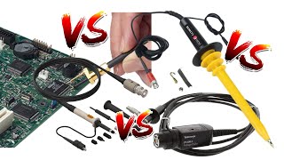
- How does a high voltage differential probe work?
How is it safe?
Is it isolated?
A teardown and some reverse engineering of the Lecroy AP031 25MHz HV Differential probe. a.k.a Sapphire Instruments SI-9001
Forum: www.eevblog.com/forum/blog/eev...
EEVblog Main Web Site: www.eevblog.com
The 2nd EEVblog Channel: / eevblog2
Support the EEVblog through Patreon!
/ eevblog
EEVblog Amazon Store (Dave gets a cut):
astore.amazon.com/eevblogstore-20
T-Shirts: teespring.com/stores/eevblog
💗 Likecoin - Coins for Likes: likecoin.pro/@eevblog/dil9/hcq3 - Наука та технологія


Hearing the audio change at around 12 minutes really freaked me out. I thought it might be someone doing their best Dave impression, but they captured your mannerisms way too perfectly. Bizzare!
Sounds like Dave came back with a cold
The resistor is not for offset, but to maximize the common mode rejection ratio. If one of the 4meg is actually 4meg+1% and the other has 4meg-1% then the CMRR is only 34dB. With the resistor you can tune the CMRR for DC to much higher values.
Shoutout to Mr. Wu!
Wu-Wuuuuu!
Mr. Who? Wu. Which Wu. The Wu, who hides the clue, so you wont say IC. So those No C buggers, No fix, RIP ‘em off again.
Dave, I think it would make a cool video if you tested the performance of this thing. In particular, I'd like to see Bode plots of the common-mode and differential-mode response, and what happens if you overload it. (Do you get a phase reversal?) BTW some of those discrete transistors may be used as clamps to protect the opamp from overloads.
18:30 A few months ago I was troubleshooting a photomultiplier charge sensitive preamp for my boss and it used an op-amp constructed from individual transistors including a higher-voltage version of the array chip shown off at this timestamp (LM3146). I thought at first that it was the part that died and did some research into sourcing a new one and it turns out that these are a nightmare to find nowadays. Luckily the dead part ended up being a 2N3096 though, but that's something to keep in mind if you have to fix something ancient that uses one of these things - you may not be able to find a proper replacement
Hi Dave! By watching the video I managed to repair my own Pintek differential probe that I just burned by extremely high discharge from Xenon lamp that I do not expected... I couldn't made it if I do not know the architecture. THANKS from Russia!!!
I bought one almost the same from Probe Master, also compatible with LeCroy. All the same features, including 4 Meg inputs and 70/700 V ranges. But mine is 100 MHz. By the way, the 70 V and 700 V reflect the output saturation (from 9.5 V supply rails) of +/- 7 V.
The input capacitor arrangement is for frequency compensation. The series string & the 4 Meg resistors form the same time constant as the parallel set with their 25 k resistor. Same idea as used on 10x probe compensations.
11:38, Dave voicover hangover edition :)
In all those years I have been watching the EEVblog I haven´t noticed Dave uses the european resistor symbol. I love it.
As a European EE, I actually prefer the "US" symbols for readability over that silly DIN standard of drawing everything as white rectangles. I reserve that for unusual/complex functions like complex chips.
The eternal fight XD.
@@JohnDoe-qx3zs It's not DIN, it's the official IEEE standard. But I agree, distinctive shapes are more readable.
The current standard even omits hints to distinguish flipflops or latches. Really annoying. I don't see the point of making everything similar and hard to distinguish. Abstraction and unification is nice (summarizing principles), but not to the point of having to interpret the schematic to guess what some of the very basic building blocks are.
Yes, comparing one of those you can get on ebay to this one would be very interesting for many viewers I believe.
Why are these probes soo bloody expensive?? doesn't look all that special in there.
Because that's what enough people are willing to pay for it.
For a divider, to be frequency flat, the capacitance in the series vs the capacitance in the shunt part has to be inverse of the divider ratio to have a flat frequency response (the math on this is your homework). In this case, 160. (4M/25k) . 6,8/3=2,27pF in the series branch (to dominate the paracitics of the resistors) 120 + 82 +82 *x =284+x . x is the trimpot. 160*2,27=363,2pF, so the trimpot is about 80 pF. This will make a flat frequency response
Back for a 2nd suck of the salve. Thank you! (again)
I love the way Dave refers to the components as "puppies."
Uhm, did I miss anything or why was the circuit board pixeled out in the thumnail which just changed?
You don't want spoilers do you?
:D Is this Game of PCBs? It's not thaaat exciting, although quite interesting.
I thought it was made out of legos!
I thought it was made of minecraft
I noticed that too. I assumed it was some kind of new youtube click-bait thing?
Maybe Mr. Yolo should start selling a competitive product to Mr. Wu's probe.
The Caps are additionally isolated due to the fact that the Body of most passive parts are not specified in terms of isolation. This means the certification bodies does not accept it unless you isolate them.
just amazing Dave you're awesome
Dave, would be cool to do the same with a isolated differential probe, and see how they do the isolation
Awesome video!
Nice video!
I built a probe based on this video I did a 750 meg ohm instead of 4 meg ohm I built mine to test high voltage on vintage tv sets I used triodes to build the diff amp
I guess the CMRR from a triode will be problematic, due to the asymmetrie between two half tube?
@@zazio5535 i used 6j5 tubes
@@God-CDXX All right..
The remained part of logo on dip-14 looks like NTE logo. It could be NTE 987 quad opamp with true differential input.
Edit: I think I found the schematic of similar design -i92.photobucket.com/albums/l40/underwurlde666/stuff/DiffProbeSMT.jpg
Would be interesting to hook it up to a sweep generator, once as a common mode input and once in differential mode to see how good it is.
I am not a fan of the scrubbed off part numbers, this shouldn't be a practice in industrial equipment. In my opinion, they don't want it to be reverse engineered and sold at a fraction of the price. Those scrubbed off numbers are an indicator that the price isn't justified.
Great teardown, and after a few years you might have figured it out - but I reckon its using something like THIS - an actual diff vid/instrumentation amp like the NE592 ...
Mr Wu did some funky soldering
Thanks so much again every time what an entertainer you are !
it works like an amplifier after it attenuates the signal , without knowing anything about it , the practice is to divide HV and LV circuits so i guess its nice to have optocoupler in there somewhere , and there you go Frankenstein is your Uncle(Bob) , TEchtronics says "1000$ please" :)
For us new players , using one of these as default - lets say probing around the inside of ham radio , that is plugged into AC , incase we accidentally come across AC side of things while probing around ?
And they scrubbed the numbers from new board as well.
This was interesting!
is the Davecad 2.0? Advanced big drawing surface with grid :)
Excelente
Parabéns
Maybe the use of 3 parallel capacitors in the voltage divider is to reduce the parasitic inductance for better high frequency performance?
I wanted to ask if you could ever do a video explaining how to read a circuit diagram and go over what the basic electronics components do? I understand this is below the scope of your blog and it's geared towards people who already know this stuff. However I can't be the only person watching who is clueless and just finds what you do entertaining. I'd like to follow along more is all. I've looked elsewhere but I think you are good at getting things across so I thought you explaining in simple non electronic terms would help. Just an idea! Love the channe.
It ain't that easy I'm afraid, that would requires many dozens of videos to even get started.
Here's somewhere to start www.talkingelectronics.com/te_interactive_index.html. As you go through each component/circuit you can search UA-cam for videos on the subject. Then you can go to the EEvBlog forum and ask for more help there.
experience... start with simple led driver then CMOS logic, transistor and MOSFETs then microcontrollers and then neons and tubes.
best is to read some books or go to sites like instructables.com
even better, watch experienced people do their work with such electronics
Suraj is correct by saying experience is what will help. When I first saw a large circuit diagram I thought there was no way I could ever understand what was going on unless I figured out what each and every component was and did beforehand. What will help the most is designing your own board (it can either be your own idea or one from a project someone's done before already), try putting it together, and the number one thing, troubleshooting. You will learn so much from your mistakes, in no time you'll be able to identify components just by looking at them. Good luck!
Do you think the switch effects its 10x/100x change by changing the current in the current source? Those extra trim pots might be for adjustments there
Thanks!
In series arranged capacitors should have bleeding resistors, not just for balancing purpose.
great explained anyway my question is why it should use jfet transistor type not the other ones ?
Still sold at Farnell under different names... We have it under two other brands.
Isn't the DIL14 IC just a negative/symmetrical voltage converter? Probe is powered with a single 6V source. So I guess it has to have a symmetrical voltage converter for the diff-amp. Something like MAX865.
Hi, Dave! Thanks for the video. Do you could say if the output coaxial cable is terminated? Thanks in advance
8:10 - Those caps are mourning :)
So with my first oscilloscope, a nice and cheap Hantek 6022BL, the protection concern comes in more of the form of the computer it’s plugged into, not necessarily the scope itself. I want to measure various parts of switchmode power supplies, so would I be looking at a differential probe, or an isolated probe? Cheers!
I'm no expert, but I know from experience that when you want to measure a signal you want to receive it as unedited as possible, so to me it already seemed obvious that there would be no real isolation as it would require recreating the signal which could easily cause contamination.
From 9:08 you can see how Dave is just not on his better days... there is a freaking resistor soldered to another (completely off-board) and he calls it NEAT? Where is Dave, can someone bring him back please?
It is not a free-standing TO-220, so everything is okay :-)
FritzenLab, It was pulled away so you can see it, the PCB was even silk screened with a symbol to denote that it is not a bodge.
Yep, I can see that. What I mean is that it is not a good practice, due to (mainly) vibration that can break it apart. This is the kind of thing that Dave hates to see in a product
Right on brotherman. -Leap
I think one side is the 10 to one split ratio and the other side is 100 to one split using feedback opamps I think you forgot about the selection switch
There is a LT1818 I think as it is a wide bandwidth chip.
Why is the board in the thumbnail all blurred out?
Dave: Probably just some obscure company
Vishay SC: that hurt mate.
no earth mains in the outlet in Norway. Hi i was watching your other video you showed a bit about osiliscope ground clip. My house has only grounded outlet in the kitchen and in the bathroom. Do i get wrong signal if i probe my arduino without earth mains on a osciliscope? New house have mains earth over all.
I was thinking for some time I would like to sit down and build my own differential probe is there any particular op amps that you would recommend
Does this require battery, or does it actually power itself by the power source you''re testing?
would one of these let you test flyback voltages on a digital scope?,
i use an old hameg 40mhz analogue scope and a 1000x probe, for testing flyback on pulse induction metal detectors, but it would be nice just to use the modern scope for everything.
9:36 reminded me of hail and pace with the banana.
Perhaps the triple caps are an attempt to avoid the potential resonance from a simple cap.
Why does the input have almost none of the protection components that would be found in a multimeter? No MOVs, PTC, etc...
Why are these components not needed for this device if it is rated to similar voltages as a multimeter? Would they lower the specs ie bandwidth?
Why does it seem like this probe is held to lower safety/protection standards? Like Dave would have torn this thing a new one if he found those back to back resistors 'flappin in the breeze' if this was in a $300 multimeter. Why is this acceptable in a HV probe?
Because there is 4M worth of resistance in each lead. That's a LOT.
Meters typically have 1-2K, they have to because of the "multi" nature and the ability to source current for the resistance range.
I would use two channels on my scope and use the subtract function.
Would that be the same Sapphire that made my graphics card?
If I just try to probe mains with a grounded oscilloscope using this probe, won't I get current from live to earth through those resistors, which would completely mess up my readings?
You should be using an Isolation Transformer on your scope even before you think of testing any type of high voltage. That removes the Ground Loop Fault problem
so if i put an isolation transformer on the switching power supply to mesaure and then use this kind of differential probe, can i blow a channel of the oscilloscope? maybe the floating voltage rise above 700v and something goes wrong. thanks.
That negative lead solder joint... Eww
It's a bit of "How ya doin'".
It's complete crap for 1kV or what this is rated at... They missed one of the small wires which now is poking against a resistor :D would be interesting if it moves somewhere else
Why does this not look like a $500 piece of equipment?
I am also not a fan of the scrubbed off part numbers, this shouldn't be a practice in industrial equipment. In my opinion, they don't want it to be reverse engineered and sold at a fraction of the price. Those scrubbed off numbers are an indicator that the price isn't justified.
10:45 But what about voltage sharing, for the caps I mean? Is there not a risk of one cap having a higher than 1 kV voltage over it?
Probably one of the reasons, why it's only rated for +-700V ;)
Oh, yeah... right, but why then have 3 capacitors ;)
+Malte Gruber Triple safety against electrocuting a million dollar engineer if one or two caps break down. Remember, that ground is solidly connected to the other (regular) oscilloscope probe and the metal case of the oscilloscope, possibly further on to the furniture. So chances are that million dollar (training+insurance cost) engineer will be touching the low voltage side a lot of the time.
John Doe
yeah ok, that make sense.
@@JohnDoe-qx3zs Strange that you are mentioning the monetary value of a user in a safety context. It's just totally irrelevant.
Also, fault currents over ground aren't really that dangerous for the user, but they might damage the oscilloscope.
Why is the pcb in the thumbnail intentionally pixelated?
Cause they tried to scrub the numbers.
how about cmrr measurement?
6:55 whats with the jaggedness of the traces?
You said you wanted a Schematic. Here is a link for a High-Voltage Differential Probe. circuitcellar.com/research-design-hub/high-voltage-differential-probe/
The OLED display on the Keysight U1461A degrades with time. My display died after about 4 years and there is no replacement part, you have to buy a new one. Very bad support form Keysight.
I see they're using a potential divider here but why is that not enough? Why the amplification?
He divides by more than 100, then uses the opamp to do the subtraction and optionally multiply back up for the 1/10 mode with no risk of letting through 100V from a divide by 10 frontend.
Without the AMP the divider would be dependend on the load, because any load (Scope, DMM, ...) has a certain resistance, that would change the Division ratio of the devider. you certainly dont want that.
0:41 captions: How not to blow up your ass illus scope
Would something like this still be built with throughhole components for some reason, or is it just because it's old?
Answer is in the video, keep watching.
You need those through hole metal film axial resistors boy just to handle the voltage else wise they like just fry on the spot.
*Mr.Wu*
Why are these so expensive other than being a relatively specialist item?
scrubbing of those numbers is how you learn karate
Mistake at 9:41 "another 100Meg resistor"
The cheap Chinese 100MHz for 120 bucks differential probes have 1:50 or higher attenuation.
I would love to see a hobbyist affordable 1:10 / 1:100 probe. Basically exactly what Dave is showing but cheaper.
Update: I see now Dave himself sells a suitable 70MHz 10x probe.
@Dave i think they scrub off the numbers just to get under your skin lol
It's a low voltage deferential probe.
Exactly. Throw in a range of 0 - 30kV or thereabouts and then we're in HV business...
IT’S OVER 9000!
(Sorry, I’ll go away now.)
Why is it all through-hole and not surface mount?
randomviewer896 High Voltage, through hole just seems more robust and industrial to me.
is that a high voltage differential probe in your pocket or are you just happy to see me?
Mr. Irrelevant I'm happy there's an HV differential probe in my pocket
Why would one use a differential probe instead of just using two normal probes on two channels without the ground clips connected and taking the difference between the channels?
therealnightwriter I don't see why there would be a boom.
Frees up a channel for other use, you might get more noise with two probes instead of one probe.
why's it camouflaged?
so that's how you test mains
Agent Office You can use a cheap $20 dmm to measure AC mains voltages, as long as it's rated high enough and not a Chinese fake.
jewel jfet? What's that?
Take it apaaaart! :D I keep laughing at that :)
LeCroy as in Teledyne LeCroy?
Yes
@@hansdietrich83 I dont remember why I asked, lol.
@@mr_gerber i just answered for lols
someone did some schematics over here
www.diyaudio.com/forums/equipment-and-tools/248505-differential-probe-reverese-engineered.html
2:52 "you can come a-..." what?
What is he saying?
come-a-gutsa
I think 'come-a-gutsa' basically means "blow the guts out".
Dave, you often use a word which I can't recognize/understand. It sounds like "efficienanos" and from the context it seems to have a meaning equal to "fanboy" or "adherent". Could you please tell what is that word?
Sorry, I am not native English speaker.
Petr Zohin Aficionados. It basically means experts on the subject.
@@rich1051414 The word really means fan or people who are into a subject/thing.
So u basically pay 700 $ for two 4 Meg resistors?
DaveCAD
Never understood why you need a junk like this. If you have a dual input oscilloscope and subtract the inputs, it should work for low frequency signals. These gadgets never work for giga Hertz anyway.
If need to measure independent signals from ground, there are very good scopes that have isolated inputs from ground.
There's issue with subtraction of two nearly equal numbers:
en.wikipedia.org/wiki/Loss_of_significance
ua-cam.com/video/nBON7zhVn10/v-deo.html
I wouldn't call this unit a "High Voltage" Probe. It is only suitable for mains-voltages which is called "low voltage" in terms of electrical energy grids. If you're talking about HV, one would exspect somthing more in the range of 10kV upwards.
Lastly, the unit itself doen't say High-Voltage anywhere. Also as you should know the little lightning-symbol doent's mean high voltage, it just means "dangerous voltage".
In terms of programming AVR chips 12V is already HV ;)
Not really. I know I'm a bit nitpicking here. In many circumstances mains-voltage might be "a relatively high voltage" but still not "high voltage". By any Definition I know (German VDE oder international IEC) " High Voltage" refers to a voltage above 1000V.
@@NebukadV There's something called high-voltage programming, where 12V are applied to a microcontroller pin, which triggers the reset. That is helpful in applications, where no pin is left as a reset pin. So the "HV" helps the chip to distinguish a reset from the usual operation.
max 1000v.......... That's still LV not HV.
first
wow this is cheap build quality... 😕
01/29/22 Micsig DP10013 High Voltage Differential Probe 1300V 100MHz 3.5ns Rise Time 50X/500X Attenuation, Tektronix P5200A P5205A P5210A $200 🧐great probe info ☕🍰
The resistor is not for offset, but to maximize the common mode rejection ratio. If one of the 4meg is actually 4meg+1% and the other has 4meg-1% then the CMRR is only 34dB. With the resistor you can tune the CMRR for DC to much higher values.