You, sir, just came at the right time! I was working with a laser driver circuit and didn't have the probing I needed to debug a flash lamp driver and didn't want to purchase an expensive 1000x probe. I think this will likely do the job for me!
I made my probe and it works wonderfully =) I used a single 50M resistor and 10x 100pF, 3kV capacitors in parallel with it. The added capacitance in the scope side was 10nF. I tested the bandwidth with my function generator and got good behavior until 7MHz which is pretty good!! Once again, thank you sir; such a simple thing but you are helping people out there 🙏
If you want a 10KV probe with 5 resistors at 10M each then I would expect each resistor to have a 2000V potential across it. At 10KV through 50M produces 2mA of current. The wattage through a single resistor should then be (2000V)(2mA) = 4W, but you choose a 1W resistor. I think you should have used a 4W resistor; with the extra 50.36K it would be large enough. I believe it is true that only the voltage drop across the resistor needs to be considered when calculating the power, as was done with the capacitors. Being certain this concept is correct would be nice. Maybe someone will verify it, but I am going to believe it for now and in the future until the hypothesis is nullified. Thanks for the video.
Sorry, 10KV through 50Mohm produces 0.2mA of current not 2mA and hence Ohms law is saved. In total the chain dissipates 10KV*0.2mA = 2W. Spread over the 5 resistors it's 0.4W per resistor, hence 1W resistor is plenty good enough.
I’m not sure about a plastic box being ok, especially a black one, black plastics use Carbon Black as a pigment, as we know carbon is conductive, if you check the datasheets for plastics material you can see that the dielectric resistance is lower for a black material compared to a white or natural coloured one, still I nice educational video though, well explained.
Good point about the black colour. I did not think about that. Although the potting resin is also black and that has a dielectric strength of 10 kV / mm. I tested the probe with was probably the better part of 9KV and did not see any issues, but I am fully with you in regarding the enclosure's isolation capability with suspicion. It should never be touched or held when its in use, nor should any other wires/components/devices touch it.
Alternative for high voltage compound: hardware store high temperature silicone (use the red one not the black). I used that stuff to repair the high voltage CRT supply (HV multiplier) in a old oscilloscope. Years latter it still holds. Takes quite a while (a few days) to cure fully.
That is an interesting idea. Do you have more details on the red stuff? I looked up a local HW store chain in the UK and while they have black, they don't have red high temp. silicone. Online I found J-B Weld 31314 which is red, but quite expensive, certainly no price advantage compared to the specialised compounds.
@@TheHWcave Not really. It is commonly available in all hardware store here (Serbia) with a wide selection of manufacturers. Commonly available as 300C silicone for stoves and furnaces. Bison is one of the foreign popular brands that should be available in the UK. Prices are around 5-7€ for standard 300mL tube.
Hi, Heinz... Another great project and video. I was glad to see that you (attempted to) pot the components in rosin. I suggest putting it in an additional box, or wrapping it with lots of electrical tape, until you can finish potting it. Shrapnel is not your friend. And, we want to keep you around...:-)
much appreciated... I have tested the probe against the most terrifying power source I have (a neon transformer that fried the resistor in the video) and did not see any arcing or other problems. Although the transformer says 6KV, I measured against earth a cool 9V on the output of the probe, meaning 9KV on the hot end. So I recon its safe (as far as those things go...) but as I mentioned in the video, I would never touch this probe when power is on and in fact I always keep well away from the whole setup.
I love this HV-Probe, you made it secure and working, tell me one thing can I use this Probe on multi meter too, and I want tovexclude the capacitors, what is your wiseable suggestion.
About the capacitors: 3kv and even 10kv ceramic disc kits seem to be all over amazon, and y1/y2 capacitors can also be bought reasonably cheap or salvaged from SMPS junk. A smaller capacitance value can always be achieved by using several in series. 5kv insulation testers are also cheap these days, so no need to blindly trust salvaged or cheap stuff. What am I missing here?
Yes, if you are willing to put the time in to test voltage rating and measure capacities and find the space to mount them safely (no arcing over), by all means that could be a solution
Merci beaucoup pour votre travail et vos explications claires et très précises. Je m'abonne car cette vidéo montre à quel point il est utile de vous suivre. Encore merci et Bravo.
Great video! Thank you very much! Keep making these videos. Looking forward to your next video. Stay safe Edit: How about enclosing it in a small sealed tube filled with mineral oil?
A great suggestion. The components need to be mechanically secure first before they can be immersed. The "string" of resistors is too fragile to suspend itself on the solder joints. Don't forget that the resistors are big and have a high mass, so any bump causes quite some mechanical stress. Another thing is that the circuit would need to kept centred to avoid touching the walls... A carrier PCB perhaps that is wide enough to just fit into the tube? I know people have put these things into cut-offs of normal copper water pipes which has the additional advantage of shielding, but the metal also causes stray capacitance issues... It really needs experimentation. But the oil-idea is something I'll keep in mind if I need to make another one or maybe for higher voltages.
Great video. You could fill the outside of your mold space up with silicone sealant prior to pouring the epoxy, or at least stick down the plastic pieces with it.
I would have used for protection and some diodes (like BAS70LS with 100mA and 2pF in series with TVS/Transient-voltage-suppression diode) in antiparallel on output
OScope in the experiment draws 300 mA to display 300 full screen! What's the purpose of applying a 1 MOhm and 56 KOhm resistances each parallel to the I MOhm internal resistance of the OScope? Oh, the Scope has flexibility to be configured!
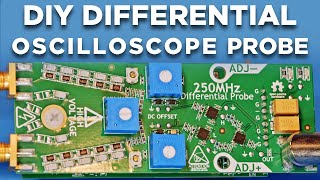
he probe is designed to see a 50K resistance on the low volts side. With scopes usually having 1M input resistance, the extra 1M in paralllel with the scopes internal 1M and the probe resistor of 56K results in a total of approx 50K. As a side note, this means you actually need to add a third 1M in parallel when using the probe with a digital multi-meter which usually has 10M input resistance. Otherwise you will get a slighly too high reading.
I have a decent high voltage 1:100 probe, that is rated as 300Mhz / 5Kv which I obviously wouldn't use it for, mostly just for mains 230v and high voltage around 500v to 1500v that are used when working with CCFL when trying to light up noble gasses for spectrum emission line reference purpose etc. , but its one of these small normal scope probes just with a rating 1:100 and kind of unsure (lack of knowledge) if its safe for my scope, as people usually push for differential probes for anything up around mains and above, but differential probes they are quite expensive and my needs are relative. Would a 1:100 probe be sufficient, when I ain't gonna work on high voltage up the four digits powergrid, but mainly EU mains and CCFL devices with relative little current behind as its batterypowered-.. my 4ch. scope is floating., so not connected to earth.. (Micsig/battery)
If the probe is rated for 5KV it is ok for standard mains 235V RMS or so. But be very careful with anything more or different signals. The peak voltage of AC is much higher than RMS (factor of 1.4) and what counts in this case is the peak. But this factor is only true for sinusoidal waves. If your test objects generate "interesting" wave forms (why else would you look at them?) , the peaks may be much higher than the RMS. Also beware of the other channels on your scope. If you connect one to high voltage, at least the outer ring may (and any other connector to the scope common ground) may well be on high voltage too.
If you are going to pot it any way (highly recommended!), almost any housing would work. Maybe you could make one yourself to measure from thin ABS sheets ?
Values for 100:1 resistor and Capacitor. And nos . What about to measure triac chopper voltage wave forms and Associated high frequency noise measurement?
Probably but at a significant risk for the user. I'd rather be safe. Maybe I am a bit paranoid but I will never hold the probe in my hand or even touch it while it is in use.
I would say probably yes. According to the data sheet of the compound RS part no 199-1402 the dielectric strength is 10kV/mm, but since they may have changed the formula in the mean time, you better check the current datasheets of whatever compound you are planning to use.
Can I make a cap divider with capacitors 150pF x 5 in series and 10nF x 3 in parallel. I can't find values below 100pF that are for more than 2kV. So the capacitance would be 10 times higher than in your scheme? Horizontal caps = 30pF and vertical = 30nF. Thanks in advance!
Possibly, but the best opamp can't recreate what has been lost in the divider, so I think the first thing would be to look at improving the divider so that can be tuned (compensated) to match the scope. A bit like adjusting your divide-by-10 scope probes. To make this work (safely) for high voltages would already be quite tricky I can imagine. Then the opamp would probably have to live in the probe and be battery powered for safety etc..
No, sorry, that is definitely not safe, and it would not work. Each of the 10M resistors has 2000V over it (when measuring 10kV). The resistors are purposely large and spaced out to minimise the danger of arcing between one end of a resistor to it's other end. No rotary switch would be able to handle 2000V difference between each contact position. If you need a 1:400 switch you would need to design a completely new divider chain for it (and encase it in resin)
To some extend yes, the protection diodes always have some leakage (= high ohm resistance) and capacitance that will be put in parallel with the scope's input resistance/capacitance. How serious that is depends on the scope and datasheets of the protection devices. To the best of my knowledge commercial (passive) high-voltage probes do not add protection devices but maybe I missed it. Best would be a test with and without protection to see if the scope picture changes significantly. Of course the test would be such that the protection devices are not activated.
I guess they are done more "properly" and have gone through many safety certifications... You are right though that from a pure component cost point of view, they are way overpriced
Probably 3 things coming together here, Firstly, I did not push the generator that hard because it gets very hot already. Higher voltages may be achievable but for how long? Secondly, the probe is loading the generator with 50 MOhm. At 1000V RMS that is already 20uA or 0.02Watt. A lot of power for this tiny thing. Thirdly maybe the advertising guys for the generator exaggerated a bit, because who would be able to actually be able to measure it?
@@TheHWcave haha, well probably the wouldnt expect someone to measure it, and you are the only one i saw doing it. About the current, they claim to output 0.4A of current, so i dont think 20uA of current is that high and it could handle it easy, its probably handling a lot more current when shortcircuit its output.. Correct me if im wrong. Anyways, im building one probe myself like this one to test one of this transformers, so thank you very much for sharing this with us... also: what did get hot, the transformer itself or the transitor??
@@gastjjs I cannot believe for a moment this would be able to do 0.4A at 15KV. That is 6000 watts ! Even at 1000VRMS its still 400 watts. Total marketing baloney! What got hot first is the transistor in my experiments.
Hi, nice video and very informative. I'd like to make the same HV probe but is there any substitute for the black potting compound that is more common and a bit cheaper to buy in most local hardware store? Regards, JB
There is some "red silicone" that a viewer recommended as a cheaper alternative, but I can't find the message with the details at the moment. I have not tried it yet. Further, there is a discussion thread on the EEVBlog with respect to cheaper potting alternatives which I would recommended to look at, but the EEVblog is currently down because of the data centre fire in Utah.
@@TheHWcave Thanks for the reply. How about the silicon used in hot glue gun and the red silicone sealant used in engine, but I am thinking the red one use in car engine is also expensive I think?
@@JB-20 For sure not the usual DIY sealant stuff because that gasses out acidic vapours that will corrode any electronic circuits. I need to dig around more to find the old comment on the recommended red compound. Also I would checkout the EEVblog forum when its back. The problem with many potting and sealant compounds is that electrical isolation is not their prime objective, but in this probe it is. With these large resistor values, any accidental leakage through the potting material would be disastrous, maybe not for safety but for performance.
@@TheHWcave Thanks, yes maybe gases cause corrosion which is one of our enemy in electronics. I also think about melting nylon material and pour into them, what's your thought about it? I am playing with tesla coils and found out that the best insulator for me is nylon and silicone...some materials like glass, rubber, plastic, mica and polyethelyn fails.
@JB-N107Lab I don't have much practical experience with potting at all (the one in the video was the first and only one so far). Melting nylon sounds way too hot. According to Wikipedia it melts at between 190 to 350 deg C, that would possibly de-solder the components but even when not, probably cause heat damage. The EEVBlog is back but apart from plenty of anecdotal stories (use candle-wax ...) not much help for non-US residence as the stuff seems not available or very expensive. However, one manufacturer MG chemicals is being distribute by Farnell in the UK. Their product B32B seems very suitable. It comes as a 375ml pack as 2 bottles that you pour the desired quantity in 2:1 ratio into a mixing bowl yourself. I calculated that in total, this will fill a volume of 362ml for £24 incl VAT (6.6p /ml) . The RS-compound in a one-use 500g bag costs £15 incl VAT and will fill in my calculation 296 ml (5p /ml) . If the volume to be potted isn't 296ml, the Farnell may be cheaper as you can make only as much as you need and reuse the rest some other time.
I built something similar and I only got to around 2MHz of bandwidth before the phase shift and distortion started. Do you know how to improve the divider to get higher bandwidth? You said something about a trimming capacitor.
Yes, if you look at normal scope probes, they always have a small trimming cap. I did not put one into this one because of the high voltage. I had no experience in building a HV probe or examined a commercial one and I thought I better err on the side of caution.... That makes the whole thing more a gamble based on tolerances of the caps used (which is considerable) the spacing of components inside the probe, the capacity of the scope, the BNC cable to connect the probe... you name it. I wonder in hindsight, why I did not tested the bandwidth and optimised it by swapping caps before putting the potting compound in. I guess its a learning experience, sorry. With swapping caps, i mean because of the tolerances they all have a different value, hence swapping say the last one with a different one from the pack may act as sort of the trimmer
Hey,I think this design can be improved by external copper shield also if you can use smaller components or less number this can decrease lead resistance and parasitic inductance which can cause problem at higher frequency and if you can choose a variable trimming cap
Wow, 100KV is way out of my comfort zone. You would need rather special (=expensive +hard to find) resistors and caps that could handle that huge voltage differential. If you instead use similar ones to the probe in the video, you need to use 10x the number (so that the differential voltage at each stage stays in the 1KV range). Just the size of such a probe would be enormous. I think I pass...
No that won't work. 9 resistors means 4.5KV over each resistor and a loss of 2W which is double what they can handle. If you managed to find at least 2W types that can handle 10KV you could use 10 of these. The voltage over each resistor is now 4KV (I would always recommend to stay below 50% of max) . The caps need to handle more than 4KV each, go for at least 7.5KV or 10KV. Even 2W resistors will get very hot (1.6W loss on each). The centre resistor needs to be doubled to 100K but to compensate for 1M scope inputs you need 120K with 500M in parallel. If you stay with 15pf caps over 10 resistors you need just 1x 1.5nF in the centre. In any case please be aware that this is dangerous stuff and you need high quality components and build this to minimise arcing. You definitely need a better housing than I did and I highly recommend never to hold or touch the probe when in use.
@@eciovsolutions Ah, ok. Looks like you plan some kind of pipe to house that many resistors ;) but maybe not a bad idea anyway. One suggestion is go for 1:10000 because for 1:1000 the output resistor is getting very high 200K which makes the accuracy depending on the input impedance of the scope/DMM. With 20K the accuracy would not change (much) whether you hang a 1M scope or a 10M DMM on it.
I want to measure voltages up to 10kv ac and dc. I would like to make probe 10:1 as my meter can handle 1000v ac/dc. Could you let us know the values of the components for such probe?
A youtube comment isn't the place to design something that can safely manage 10000V. Don't get me wrong but building a *safe* DIY probe needs a lot of experience, from component selection to building and enclosing. The design is the easiest part. Your safety is on the line and I don't want to be responsible for this. Therefore, I honestly think it would be much safer to buy a high voltage probe. You can find some used ones which should be ok as long as they are in good condition, no cracks of the enclosure, undamaged cables. They tend to be higher 1:100 or 1:1000 but that is ok, you just have to use a more range on your meter. Anyway a probe delivering 1000V as the low output is scary by itself Much better to step it down into something truly harmless like 10V. Also be aware that most meters may be able to do 1000V DC but not 1000V AC. Mostly AC top ranges are limited to 750V (RMS) because the peak voltage of that 750AC is just about 1000V (1058V to be exact)
@TheHWcave Hi mate, thanks for your prompt response. Yes, you are right 1:100 probably is a better idea :) I just thought that the higher ratio probes will be less accurate as you have to use more components that have their accuracy limits.
Hi TheJavaSync. It depends on the input circuitry of your scope. The probe is designed for 1 Mohm 13 pF inputs. The 1 Mohm is fairly common even in cheap scopes. The 13 pF are not terribly important as long as your scope is roughly in the same order of magnitude. If you scope has a different input resistance, you can always adjust the parallel resistors so they combine to 50K (to work as a 1:1000 divider with the 5x10 Meg series resistors) For example, if your scope has 10 MOhm input resistance, you can use the same trick I use when connecting the probe to one of my multimeters (which also have 10 Mohm input resistance): simply add an additional parallel resistor of 1 Mohm, which brings the whole parallel resistance to near-enough 50K. Another thing to consider: The Rigol scope allows you to set the divider scale for each input on the scope. This is purely so that measurement readouts use the right scale and unit on the screen. If your scope does not offer a setting of 1:1000 at the input, you need to leave it at x1 and do the conversion in your head by remembering that 1V shown on your scope means 1000V on the input of the probe.
Thank You for your reply, Sir I'jll find datashret for my particular scope, & follow your instructions, I think easy for me to find all componenrs at local store.. Really sorry for annoying You & for my bad English,
Not really. First there is no chain, 1Gohm to 1 Mohm is already 1000:1. This means you have to find a 1 Gohm that can handle the full voltage and then a capacitor that can handle the full voltage. But the biggest problem is that a probe output resistance of 1M is way too high and in the same magnitude of the scope's input resistance. The divider accuracy would be seriously affected by the scope. The result would be very difficult to predict (from scope to scope) and also probably depend on what attenuation is currently selected on the scope. This happens with the current design as well of course but because its output at 50K is only 1/20 of the scope's input resistance, it dominates and the scope's influence can be ignored (this is not a super high precision design anyway).
Most are 1M but some cheaper ones and PC-scopes are not. The probe's output resistance (50K in mine) is in parallel to the scope's input resistance of 1M, which is makes it effectively 47K . But a 1M output resistance would become 500K, a huge change and spoiling the calculated ratio of the probe
Yes, that is why the caps are in there. But the frequency range isn't that great, so do expect some distortion on rectangle signals of higher frequencies.
Surely it's easier to watch and pay attention to a video, rather than asking such a question? In fact, if you need to ask the question, then you really shouldn't be "Daily Fixing" any kind of electronics. 😂😂
Vishay 10MΩ 1W Metal Glaze Resistor ±5% VR68000001005JAC00 and the caps are Vishay Single Layer Ceramic Capacitor SLCC 15pF 3kV dc ±20% U2J (N750) Dielectric 564R Series


Great work, was just figuring out how others made their 1000X probes and stumbled across your excellent project.
Thank you for sharing this project with us, very accurate design !
Oscilloscope attenuators are capacitive dividers. The resistors are just there to allow DC operation.
You, sir, just came at the right time! I was working with a laser driver circuit and didn't have the probing I needed to debug a flash lamp driver and didn't want to purchase an expensive 1000x probe. I think this will likely do the job for me!
I made my probe and it works wonderfully =)
I used a single 50M resistor and 10x 100pF, 3kV capacitors in parallel with it. The added capacitance in the scope side was 10nF. I tested the bandwidth with my function generator and got good behavior until 7MHz which is pretty good!!
Once again, thank you sir; such a simple thing but you are helping people out there 🙏
If you want a 10KV probe with 5 resistors at 10M each then I would expect each resistor to have a 2000V potential across it. At 10KV through 50M produces 2mA of current. The wattage through a single resistor should then be (2000V)(2mA) = 4W, but you choose a 1W resistor. I think you should have used a 4W resistor; with the extra 50.36K it would be large enough.
I believe it is true that only the voltage drop across the resistor needs to be considered when calculating the power, as was done with the capacitors. Being certain this concept is correct would be nice. Maybe someone will verify it, but I am going to believe it for now and in the future until the hypothesis is nullified.
Thanks for the video.
Sorry, 10KV through 50Mohm produces 0.2mA of current not 2mA and hence Ohms law is saved. In total the chain dissipates 10KV*0.2mA = 2W. Spread over the 5 resistors it's 0.4W per resistor, hence 1W resistor is plenty good enough.
Great project ! Many thanks for the theory and demonstration of practical results. 👍
Super job - and many thanks for listing the parts and suppliers - really helpful to me.
Nice project!
The high-frequency sound came through your video
@ 13:47 it was ear piercing!
BRAVO ! Your video is comprehensive and very insteresting. Thank you very much !
I’m not sure about a plastic box being ok, especially a black one, black plastics use Carbon Black as a pigment, as we know carbon is conductive, if you check the datasheets for plastics material you can see that the dielectric resistance is lower for a black material compared to a white or natural coloured one, still I nice educational video though, well explained.
Good point about the black colour. I did not think about that. Although the potting resin is also black and that has a dielectric strength of 10 kV / mm. I tested the probe with was probably the better part of 9KV and did not see any issues, but I am fully with you in regarding the enclosure's isolation capability with suspicion. It should never be touched or held when its in use, nor should any other wires/components/devices touch it.
Alternative for high voltage compound: hardware store high temperature silicone (use the red one not the black). I used that stuff to repair the high voltage CRT supply (HV multiplier) in a old oscilloscope. Years latter it still holds. Takes quite a while (a few days) to cure fully.
That is an interesting idea. Do you have more details on the red stuff? I looked up a local HW store chain in the UK and while they have black, they don't have red high temp. silicone. Online I found J-B Weld 31314 which is red, but quite expensive, certainly no price advantage compared to the specialised compounds.
@@TheHWcave Not really. It is commonly available in all hardware store here (Serbia) with a wide selection of manufacturers. Commonly available as 300C silicone for stoves and furnaces. Bison is one of the foreign popular brands that should be available in the UK. Prices are around 5-7€ for standard 300mL tube.
@@TheHWcave Something like this: www.uksealants.co.uk/everbuild-heatmate-high-temperature-silicone.html
Thanks for the link. I may give that compound a try in the new year
Hi, Heinz... Another great project and video. I was glad to see that you (attempted to) pot the components in rosin. I suggest putting it in an additional box, or wrapping it with lots of electrical tape, until you can finish potting it. Shrapnel is not your friend. And, we want to keep you around...:-)
much appreciated... I have tested the probe against the most terrifying power source I have (a neon transformer that fried the resistor in the video) and did not see any arcing or other problems. Although the transformer says 6KV, I measured against earth a cool 9V on the output of the probe, meaning 9KV on the hot end. So I recon its safe (as far as those things go...) but as I mentioned in the video, I would never touch this probe when power is on and in fact I always keep well away from the whole setup.
I love this HV-Probe, you made it secure and working, tell me one thing can I use this Probe on multi meter too, and I want tovexclude the capacitors, what is your wiseable suggestion.
About the capacitors: 3kv and even 10kv ceramic disc kits seem to be all over amazon, and y1/y2 capacitors can also be bought reasonably cheap or salvaged from SMPS junk. A smaller capacitance value can always be achieved by using several in series. 5kv insulation testers are also cheap these days, so no need to blindly trust salvaged or cheap stuff. What am I missing here?
Yes, if you are willing to put the time in to test voltage rating and measure capacities and find the space to mount them safely (no arcing over), by all means that could be a solution
Merci beaucoup pour votre travail et vos explications claires et très précises. Je m'abonne car cette vidéo montre à quel point il est utile de vous suivre. Encore merci et Bravo.
Great video! Thank you very much! Keep making these videos. Looking forward to your next video. Stay safe
Edit: How about enclosing it in a small sealed tube filled with mineral oil?
A great suggestion. The components need to be mechanically secure first before they can be immersed. The "string" of resistors is too fragile to suspend itself on the solder joints. Don't forget that the resistors are big and have a high mass, so any bump causes quite some mechanical stress. Another thing is that the circuit would need to kept centred to avoid touching the walls... A carrier PCB perhaps that is wide enough to just fit into the tube? I know people have put these things into cut-offs of normal copper water pipes which has the additional advantage of shielding, but the metal also causes stray capacitance issues... It really needs experimentation. But the oil-idea is something I'll keep in mind if I need to make another one or maybe for higher voltages.
Great video. You could fill the outside of your mold space up with silicone sealant prior to pouring the epoxy, or at least stick down the plastic pieces with it.
Thanks. Good tips. This was my first attempt at potting, so its a bit rough
Very interesting, thanks!
Thank you Sir, that is exactly what I was looking for.
Very helpful. Thank you.
Very nice video. Thank you!
I would have used for protection and some diodes (like BAS70LS with 100mA and 2pF in series with TVS/Transient-voltage-suppression diode) in antiparallel on output
TVS is always in antiparallel?
Fantastic thanks alot!
OScope in the experiment draws 300 mA to display 300 full screen!
What's the purpose of applying a 1 MOhm and 56 KOhm resistances each parallel to the I MOhm internal resistance of the OScope?
Oh, the Scope has flexibility to be configured!
he probe is designed to see a 50K resistance on the low volts side. With scopes usually having 1M input resistance, the extra 1M in paralllel with the scopes internal 1M and the probe resistor of 56K results in a total of approx 50K. As a side note, this means you actually need to add a third 1M in parallel when using the probe with a digital multi-meter which usually has 10M input resistance. Otherwise you will get a slighly too high reading.
Amazing video, could anything be done to help it work better at high frequency?
I have a decent high voltage 1:100 probe, that is rated as 300Mhz / 5Kv which I obviously wouldn't use it for, mostly just for mains 230v and high voltage around 500v to 1500v that are used when working with CCFL when trying to light up noble gasses for spectrum emission line reference purpose etc. , but its one of these small normal scope probes just with a rating 1:100 and kind of unsure (lack of knowledge) if its safe for my scope, as people usually push for differential probes for anything up around mains and above, but differential probes they are quite expensive and my needs are relative.
Would a 1:100 probe be sufficient, when I ain't gonna work on high voltage up the four digits powergrid, but mainly EU mains and CCFL devices with relative little current behind as its batterypowered-.. my 4ch. scope is floating., so not connected to earth.. (Micsig/battery)
If the probe is rated for 5KV it is ok for standard mains 235V RMS or so. But be very careful with anything more or different signals. The peak voltage of AC is much higher than RMS (factor of 1.4) and what counts in this case is the peak. But this factor is only true for sinusoidal waves. If your test objects generate "interesting" wave forms (why else would you look at them?) , the peaks may be much higher than the RMS. Also beware of the other channels on your scope. If you connect one to high voltage, at least the outer ring may (and any other connector to the scope common ground) may well be on high voltage too.
I cut out a small 7”x2” piece of phenolic and inserted turrets for the circuit. Problem is that I can’t find a project box the right size
If you are going to pot it any way (highly recommended!), almost any housing would work. Maybe you could make one yourself to measure from thin ABS sheets ?
Thanks For Sharing
Values for 100:1 resistor and Capacitor. And nos .
What about to measure triac chopper voltage wave forms and
Associated high frequency noise measurement?
Partially exposing components might help with heat dissipation
Probably but at a significant risk for the user. I'd rather be safe. Maybe I am a bit paranoid but I will never hold the probe in my hand or even touch it while it is in use.
Thanks for this video! I wondering how the impedance of the BNC connector affects the calculation? Did you use a 50 Ohm variant? Thanks for your reply
No I did not. The output is calculated to go into the 1 MOhm input impedance of my Rigol 1054z scope (which doesn't offer 50 Ohm)
hmmm excellent job, i wonder if the black epoxy can be used to repair a flyback leaking high voltage !?
I would say probably yes. According to the data sheet of the compound RS part no 199-1402 the dielectric strength is 10kV/mm, but since they may have changed the formula in the mean time, you better check the current datasheets of whatever compound you are planning to use.
Can I make a cap divider with capacitors 150pF x 5 in series and 10nF x 3 in parallel. I can't find values below 100pF that are for more than 2kV. So the capacitance would be 10 times higher than in your scheme? Horizontal caps = 30pF and vertical = 30nF. Thanks in advance!
I think that should still work. But for high frequencies say 100kHz the higher value caps will load the input source quite a bit more of course.
Jakie jest pasmo przenoszenia takiej sondy ???
Very good!!! Would you please post the cost of the resistors, the caps, and of the potting material? And maybe the details?
I have updated the description. Prices are from April 2020 in GBP and exclude VAT
@@TheHWcave thank you!!!
Can this also be used for high voltage AC as input? I wanted to study the frequency of my high voltage AC source
Yes, it is designed to work for AC as well (using the caps as capacitive divider). It's bandwidth isn't that great though, 3 MHz is all I got.
Hi great video! Do you think adding an opamp would help increase probe bandwidth?
Possibly, but the best opamp can't recreate what has been lost in the divider, so I think the first thing would be to look at improving the divider so that can be tuned (compensated) to match the scope. A bit like adjusting your divide-by-10 scope probes. To make this work (safely) for high voltages would already be quite tricky I can imagine. Then the opamp would probably have to live in the probe and be battery powered for safety etc..
that's cool. Is it safe to connect read the voltage at different points if i wanted to get a 1:400 reduction? can this be done with rotary switch?
No, sorry, that is definitely not safe, and it would not work. Each of the 10M resistors has 2000V over it (when measuring 10kV). The resistors are purposely large and spaced out to minimise the danger of arcing between one end of a resistor to it's other end. No rotary switch would be able to handle 2000V difference between each contact position. If you need a 1:400 switch you would need to design a completely new divider chain for it (and encase it in resin)
comprehensive
Hi, adding some protection (back-to-back transistors, tvs, gdt, zener, ...) on the oscilloscope side will mess with the probe or its performance?
To some extend yes, the protection diodes always have some leakage (= high ohm resistance) and capacitance that will be put in parallel with the scope's input resistance/capacitance. How serious that is depends on the scope and datasheets of the protection devices. To the best of my knowledge commercial (passive) high-voltage probes do not add protection devices but maybe I missed it. Best would be a test with and without protection to see if the scope picture changes significantly. Of course the test would be such that the protection devices are not activated.
Why does this cost >$400 when buying on Digikey?
I guess they are done more "properly" and have gone through many safety certifications... You are right though that from a pure component cost point of view, they are way overpriced
have you done a clamp for amps messuerment by the scope home made too ? for high frequency ?
I have done a current clamp video but the clamp I used SCT013-100 is limited to 1KHz
Hi, i see you tested the high voltage generator which claims to output 15kv, and you are only reading 5kvpp or am i missing something? thank you
Probably 3 things coming together here, Firstly, I did not push the generator that hard because it gets very hot already. Higher voltages may be achievable but for how long? Secondly, the probe is loading the generator with 50 MOhm. At 1000V RMS that is already 20uA or 0.02Watt. A lot of power for this tiny thing. Thirdly maybe the advertising guys for the generator exaggerated a bit, because who would be able to actually be able to measure it?
@@TheHWcave haha, well probably the wouldnt expect someone to measure it, and you are the only one i saw doing it. About the current, they claim to output 0.4A of current, so i dont think 20uA of current is that high and it could handle it easy, its probably handling a lot more current when shortcircuit its output.. Correct me if im wrong.
Anyways, im building one probe myself like this one to test one of this transformers, so thank you very much for sharing this with us...
also: what did get hot, the transformer itself or the transitor??
@@gastjjs I cannot believe for a moment this would be able to do 0.4A at 15KV. That is 6000 watts ! Even at 1000VRMS its still 400 watts. Total marketing baloney! What got hot first is the transistor in my experiments.
Hi, nice video and very informative.
I'd like to make the same HV probe but is there any substitute for the black potting compound that is more common and a bit cheaper to buy in most local hardware store?
Regards, JB
There is some "red silicone" that a viewer recommended as a cheaper alternative, but I can't find the message with the details at the moment. I have not tried it yet. Further, there is a discussion thread on the EEVBlog with respect to cheaper potting alternatives which I would recommended to look at, but the EEVblog is currently down because of the data centre fire in Utah.
@@TheHWcave Thanks for the reply. How about the silicon used in hot glue gun and the red silicone sealant used in engine, but I am thinking the red one use in car engine is also expensive I think?
@@JB-20 For sure not the usual DIY sealant stuff because that gasses out acidic vapours that will corrode any electronic circuits. I need to dig around more to find the old comment on the recommended red compound. Also I would checkout the EEVblog forum when its back. The problem with many potting and sealant compounds is that electrical isolation is not their prime objective, but in this probe it is. With these large resistor values, any accidental leakage through the potting material would be disastrous, maybe not for safety but for performance.
@@TheHWcave Thanks, yes maybe gases cause corrosion which is one of our enemy in electronics. I also think about melting nylon material and pour into them, what's your thought about it?
I am playing with tesla coils and found out that the best insulator for me is nylon and silicone...some materials like glass, rubber, plastic, mica and polyethelyn fails.
@JB-N107Lab I don't have much practical experience with potting at all (the one in the video was the first and only one so far). Melting nylon sounds way too hot. According to Wikipedia it melts at between 190 to 350 deg C, that would possibly de-solder the components but even when not, probably cause heat damage.
The EEVBlog is back but apart from plenty of anecdotal stories (use candle-wax ...) not much help for non-US residence as the stuff seems not available or very expensive. However, one manufacturer MG chemicals is being distribute by Farnell in the UK. Their product B32B seems very suitable. It comes as a 375ml pack as 2 bottles that you pour the desired quantity in 2:1 ratio into a mixing bowl yourself. I calculated that in total, this will fill a volume of 362ml for £24 incl VAT (6.6p /ml) . The RS-compound in a one-use 500g bag costs £15 incl VAT and will fill in my calculation 296 ml (5p /ml) . If the volume to be potted isn't 296ml, the Farnell may be cheaper as you can make only as much as you need and reuse the rest some other time.
I built something similar and I only got to around 2MHz of bandwidth before the phase shift and distortion started. Do you know how to improve the divider to get higher bandwidth? You said something about a trimming capacitor.
Yes, if you look at normal scope probes, they always have a small trimming cap. I did not put one into this one because of the high voltage. I had no experience in building a HV probe or examined a commercial one and I thought I better err on the side of caution.... That makes the whole thing more a gamble based on tolerances of the caps used (which is considerable) the spacing of components inside the probe, the capacity of the scope, the BNC cable to connect the probe... you name it. I wonder in hindsight, why I did not tested the bandwidth and optimised it by swapping caps before putting the potting compound in. I guess its a learning experience, sorry. With swapping caps, i mean because of the tolerances they all have a different value, hence swapping say the last one with a different one from the pack may act as sort of the trimmer
Hey,I think this design can be improved by external copper shield also if you can use smaller components or less number this can decrease lead resistance and parasitic inductance which can cause problem at higher frequency and if you can choose a variable trimming cap
I need a 100KV probe! Build it?
Wow, 100KV is way out of my comfort zone. You would need rather special (=expensive +hard to find) resistors and caps that could handle that huge voltage differential. If you instead use similar ones to the probe in the video, you need to use 10x the number (so that the differential voltage at each stage stays in the 1KV range). Just the size of such a probe would be enormous. I think I pass...
Hi thx for upload , if i need to go 40KV , just need to add 4X 10M resistors & 15pf capacitors?
No that won't work. 9 resistors means 4.5KV over each resistor and a loss of 2W which is double what they can handle. If you managed to find at least 2W types that can handle 10KV you could use 10 of these. The voltage over each resistor is now 4KV (I would always recommend to stay below 50% of max) . The caps need to handle more than 4KV each, go for at least 7.5KV or 10KV. Even 2W resistors will get very hot (1.6W loss on each). The centre resistor needs to be doubled to 100K but to compensate for 1M scope inputs you need 120K with 500M in parallel. If you stay with 15pf caps over 10 resistors you need just 1x 1.5nF in the centre. In any case please be aware that this is dangerous stuff and you need high quality components and build this to minimise arcing. You definitely need a better housing than I did and I highly recommend never to hold or touch the probe when in use.
@@TheHWcave thanks ,appreciated the advice, I mean 4 sets of your one 5x4=20 of 10M resistors
@@eciovsolutions Ah, ok. Looks like you plan some kind of pipe to house that many resistors ;) but maybe not a bad idea anyway. One suggestion is go for 1:10000 because for 1:1000 the output resistor is getting very high 200K which makes the accuracy depending on the input impedance of the scope/DMM. With 20K the accuracy would not change (much) whether you hang a 1M scope or a 10M DMM on it.
I want to measure voltages up to 10kv ac and dc. I would like to make probe 10:1 as my meter can handle 1000v ac/dc. Could you let us know the values of the components for such probe?
A youtube comment isn't the place to design something that can safely manage 10000V. Don't get me wrong but building a *safe* DIY probe needs a lot of experience, from component selection to building and enclosing. The design is the easiest part. Your safety is on the line and I don't want to be responsible for this. Therefore, I honestly think it would be much safer to buy a high voltage probe. You can find some used ones which should be ok as long as they are in good condition, no cracks of the enclosure, undamaged cables. They tend to be higher 1:100 or 1:1000 but that is ok, you just have to use a more range on your meter. Anyway a probe delivering 1000V as the low output is scary by itself Much better to step it down into something truly harmless like 10V. Also be aware that most meters may be able to do 1000V DC but not 1000V AC. Mostly AC top ranges are limited to 750V (RMS) because the peak voltage of that 750AC is just about 1000V (1058V to be exact)
@TheHWcave Hi mate, thanks for your prompt response. Yes, you are right 1:100 probably is a better idea :) I just thought that the higher ratio probes will be less accurate as you have to use more components that have their accuracy limits.
@TheHWcave, did I miss the common ground wire in the video or the HV and LV side grounds are not connected at all?
So, is it compatible with any oscope? I use cheap chinese usb oscope.
Anw, thank You, Sir
Loved your vids
Hi TheJavaSync. It depends on the input circuitry of your scope. The probe is designed for 1 Mohm 13 pF inputs. The 1 Mohm is fairly common even in cheap scopes. The 13 pF are not terribly important as long as your scope is roughly in the same order of magnitude. If you scope has a different input resistance, you can always adjust the parallel resistors so they combine to 50K (to work as a 1:1000 divider with the 5x10 Meg series resistors)
For example, if your scope has 10 MOhm input resistance, you can use the same trick I use when connecting the probe to one of my multimeters (which also have 10 Mohm input resistance): simply add an additional parallel resistor of 1 Mohm, which brings the whole parallel resistance to near-enough 50K.
Another thing to consider: The Rigol scope allows you to set the divider scale for each input on the scope. This is purely so that measurement readouts use the right scale and unit on the screen. If your scope does not offer a setting of 1:1000 at the input, you need to leave it at x1 and do the conversion in your head by remembering that 1V shown on your scope means 1000V on the input of the probe.
Thank You for your reply, Sir
I'jll find datashret for my particular scope, & follow your instructions, I think easy for me to find all componenrs at local store..
Really sorry for annoying You & for my bad English,
no worries, you are doing very well
Wouldn't it work if we use main resistor chain 1Gohm and use input 1M as the second resistor in the divider?
Not really. First there is no chain, 1Gohm to 1 Mohm is already 1000:1. This means you have to find a 1 Gohm that can handle the full voltage and then a capacitor that can handle the full voltage. But the biggest problem is that a probe output resistance of 1M is way too high and in the same magnitude of the scope's input resistance. The divider accuracy would be seriously affected by the scope. The result would be very difficult to predict (from scope to scope) and also probably depend on what attenuation is currently selected on the scope. This happens with the current design as well of course but because its output at 50K is only 1/20 of the scope's input resistance, it dominates and the scope's influence can be ignored (this is not a super high precision design anyway).
@@TheHWcave I though 1M scope input resistance is a precisely controlled value, so that probes just add in series resistor (and capacitor).
Most are 1M but some cheaper ones and PC-scopes are not. The probe's output resistance (50K in mine) is in parallel to the scope's input resistance of 1M, which is makes it effectively 47K . But a 1M output resistance would become 500K, a huge change and spoiling the calculated ratio of the probe
Can this schematic be used in AC? (because of the series capacitors)
Yes, that is why the caps are in there. But the frequency range isn't that great, so do expect some distortion on rectangle signals of higher frequencies.
Surely it's easier to watch and pay attention to a video, rather than asking such a question?
In fact, if you need to ask the question, then you really shouldn't be "Daily Fixing" any kind of electronics. 😂😂
Use some resine to insulates
What is the part number of the resistors you are using?
Vishay 10MΩ 1W Metal Glaze Resistor ±5% VR68000001005JAC00 and the caps are
Vishay Single Layer Ceramic Capacitor SLCC 15pF 3kV dc ±20% U2J (N750) Dielectric 564R Series
@@TheHWcave Thank you so much
👍