Thanks John. You're one of my top 10 go-to UA-cam techs. Really need help on my heat pump heat mode troubleshooting skills and this video helps a lot. Thanks for sharing your knowledge.
Thank you. U never would have thought when I started doing this that someone might say that but am glad to hear that you are putting in your time to learn more. Learn something from anyone...whether it is what to do or not to do!
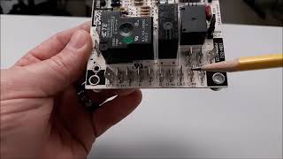
0:49 it would have been nice for you to finish that thought, similar to r coming in, c going back, y comes in then goes out of that other y just to the right (guessing thats how this board is setup), and goes to the compressor/condenser fan contactor. edit: 1:56 nvm you cover it at this timestamp.
The little square black box in the defrost board will do the job when the system defrost, the contact gonna turn from NC to NO to shut the CFM off, right? Thank you sir!
The 2 wires pink are the temperature switch will always have 24 voltage on the top terminal of the plug, then send it to the sensor, and the other plug in the bottom is return path with no 24 unless the condenser coils get frost and it will have the 24v send back to the board then run the defrost, right? Thank you sir!
Yes. It is a simple switch and has 24v on one side of it all the time and it only passes power back to the board once it senses that the coil is cold enough.
Thanks for the cool info John. I have a unit where there';s zero voltage coming from the board ..on any termonals.. I checked the coninuity of the sensors .. There's 220V on the board relay termonals . Thinking this board is dead! I ordered a replacement!f How say you?
Thanks for the video. I tested the voltage on my HK32EA001. The voltage reading between C and R is 5.5v. In the video you said it should be 24v. Can you advise.
You need to find a full 24v! You need to backtrack and find power...if you got 5.5 at the wire nuts outside the you need to check R and C and the air handler connections. If you have it on the air handler end of the wire but not on the heat pump end...may be a wire connection (loose wire nuts, corrosion, etc) or a break in the wire!
So in the state like FL is hot so the defrost function won’t need, right? It usually run the defrost when the condenser coils is frost? Just a little bit confuse and I am living in FL Thank you sir!
Florida might be a little warm for wintery conditions and you might not even use a defrost...like you said. It may also be warm enough where you are at to thaw out when the unit isn't running. Lot of weather dependent possibilities! You are on the right track i think.
Hi, so during defrost the indoor coil is cold AND the auxiliary heat is on at the same time? And there's very hot air blowing across the coil? Is this correct? Great video. Thanks
Thanks. Defrost mode is really just your a/c on with the heat strips running at the same time if you have just a standard all electric setup. Your defrost board will handle all of that and not the thermostat of course. The heat strips just temper the air so that it isn't a blast of cold air coming through the vents in winter. Not sure about the "very hot air" you mentioned.
Hi John, love this video... I have the HK32EA003, the board is fried around the transistors and resistors... could that cause the outdoor unit not coming on? Contactor, Capacitors, and everything seem normal.
Short answer,...Yes. If the board has burnt circuit it is very likely. Of course I could go with the..."you still would need to troubleshoot to be sure" route but I think that board is simple enough that it contactor outside should be powered if you have 24V on 'Y' going into it. If power is going in on 'Y' and the unit isn't running then those burnt transistors, resistors, etc. are probably to blame.
I'm a little confused. At 10:19, you read 0V on your multimeter, and stated that was because the switch was open. If electricity is attempting to flow through a switch, but that switch is open, then, when you place your leads on either side of that switch, you should be reading a measurable amount of potential difference (aka, voltage). Is that 'switch' that you were referring to instead perhaps a load, by any chance? 🤔
It is because of the way I was checking it. That circuit is just a hot 24v leaving the board, going to the switch that monitors the coil temperature. I used the 24v common from the main plug to check for power going into the switch (1st check) to read 25 volts and then out of the switch (2nd check) and got 0 volts. I get what you are saying but in this case it is just because of the way I did the voltage checking. I like the hopscotch method best and that is the way I did it in that part of the video.
Okay, it makes much better sense now, only when you told me that you used the hopscotching method! God, please don't say, "It's just the way that I was checking it." Long story short, I am still in school right now for HVACR. (I already have a background and experience with electricity.) When it came time for my instructor to teach the class about voltage, he never once used the words 'potential difference' in describing the measuring of voltage. Instead, he simply said, "It's just the way the machine reads it." 🤦♂ As an instructor of HVACR, he should've explained to the class that the 'machine', or multimeter, is like a calculator; it is merely subtracting the DIFFERENCE in POTENTIAL voltage between the outside of the leads and the voltage on the inside. (He also never once used the terms 'backseating' and/or 'frontseating' when describing the fully opening and/or closing of service valves on units. It's kind of sad that after paying this college thousands of dollars of my hard-earned money, I learned those terms from studying a book that I had to pay an additional $150 for on Amazon.) I know; it's probably petty. I don't why that causes my OCD to let that bother me so much... 😆
Everybody is different in their explanation of stuff. I would say not to be too tough on the teacher because they can only teach it the way they know it! School should only be the beginning and make you dig a little deeper on your own. I know I have been through the same thing starting out in the field. You doing extra research and studying only makes you better!
Once the compressor contactor gets a call to run, it also sends 24v to T1? And once the compressor has been running for the desire amount of time selected without turning off the defrost will engage? Which will still keep the compressor contactor intact. Then it would also be in defrost for the same amount of time selected? Hope this doesn't sound confusing. Just wondering the main purpose of T1 and how it works. Thanks
T1 is supposed to track how long the contactor "Y" circuit has been energized...simulating how long the compressor has run. It doesnt have to be 30/60/90 minutes consecutively. Once the run time and coil temperature are ready the board goes into defrost. Defrost doesn't last more than 10 min but can be quicker.
Yes. Defrost is a fixed 10 minute max on many time/temperature boards like that unless the coil temp warms up quicker and the coil is cleared of frost.
That one must be a Demand Defrost board. There are 2 temp sensors (thermistors) tied to the board. OCT is Outdoor Coil Temp, OAT is Outdoor Air Temp. I believe it is a purple wire factory connected to the D terminal and yes it goes to the white wire we typically use to turn on the heat strips in Defrost!
My current situation: Split System HVAC compressor and fan do not operate. Indoor unit and thermostat working properly. Capacitor is new. When I depress the plunger on the relay, they both start. There is no 24v to relay coil. Coil has continuity. Pressure switches have continuity. OF1 & OF2 has continuity. What's left? Could the HK32EA007 Board be bad?
You have to find the 24v for the contactor coil..sounds obvious I know... Is it coming into the outdoor unit at all on the thermostat wiring from the air handler? If not, contactor shouldn't be running. May have a float switch in the drain keeping it from passing to the outdoor unit.
So, oddly enough, I went to the outside unit to check voltages at the board with my DMM. As I checked power to Common at the T1 C C O connector, the Relay Coil energized and the AC has been running fine ever since. Not sure what happened to make it do that? Thanks for your response!!!
It is possible. You probably have two black wires (for the outdoor fan motor) on the relay of the board. One comes from the contactor and goes into the relay, the other goes from the relay to the fan motor. Take the fan motor wire and plug it onto the contactor where the other black wire is coming from. This is a way to bypass the relay and see if the problem is the board or not. The fan should come on with the compressor in a/c mode so long as the capacitor and motor itself are good.
What do you mean 'going to defrost board'? Did you find it in the circuit before the board or are you saying it is kinda because of the 'R' terminal/circuit on the main plug of the board?
Does this board have anything to do with an issue I’m having (2.5t carrier heat pump): 1) When power is applied to the outside condensing unit, thermostat off, compressor and fan runs and will not turn off. 24v on the cyan/pink stripe and energizing contactor.
Anything is possible but that is not probably the case. The circuit on this board that goes to the contactor is pretty much a straight shot through the board...no switches to stick closed. With the thermostat is set to OFF, I would check for 24v between the yellow wire and common wire (whatever color it is) in the low voltage connections at the air handler. If you have it there then it might be a bad thermostat. I have seen a few a stances of rubbed wires and it made a connection between the red and yellow wires...or someone with a weed eater near the outdoor unit maybe?
@@johnjennings-JJ thanks 🙏. That isn’t the case for me unfortunately. R O G Y are all off on the contactor side inside. It boggles my mind where and why that cyan/pink stripe is energized and from where. I’ll have to take off the outside fan and follow that wire this weekend.
I tested the power getting to the board and it read 25-25V then the unit immediately shut off and now no power. Could this still be the defrost board or likely a bigger issue?
The power for that board comes from inside so I wouldn't blame the defrost board yet if you are talking about 24v power at the R & C connection. Probably need to check for power at the transformer to make sure. If you have 24v on the secondary output, you have to follow it to see where you have and don't have it anymore.
I wouldn't say that. Sounds like a loose wire or something. T1 gets power from the 24v 'Y' side of the contactor coil so no 0v is probably a loose wire from contactor to board or either you don't 24v going to the contactor yet.
The board needs to see a closed defrost coil sensor, or you can jump it out by removing the plug from the board and place a jumper wire in its place, then use something metallic and sort the 2 "test" pins together for a short period of time. Usually between like 7 and 25 seconds. If everything is ok it should go into defrost and stay there until the defrost coil sensor opens. Make sure to remove the screwdriver or whatever you are using to short the test pins together as soon as you hear it switch over to defrost.
@@johnjennings-JJ ThankYou, I replaced a failed defrost temperature sensor yesterday and needed to test the defrost cycle after installing the replacement dfts.
It should come from 1 of 2 places. The thermostat sends it in normal operation or the defrost board during heat mode if the unit outside needs to defrost.
@johnjennings487 Thank you for quick reply! I just install 3 ton Goodman heat pump I have 18/5 coming from 3 ton Goodman heat pump to the airhandler midway I spliced with the thermostat wires or should I run thermostat wires straight to the airhandler and connect both 18/5 condenser and thermostat to the airhandler? Reason why I'm asking my reverse valve on the condenser makes buzzing noise ( and no 24v only 17v I'm a EPA certified based on long island NY, I mostly install minisplits Fujitsu, Mitsubishi etc
I prefer a straight run of new wire on a new system but splices aren't bad as long as it works I guess. Every job has its own issues. I wouldn't focus on new vs spliced right now unless you find out that your voltage drop is due to the old wiring or loose connection, etc. You have to find the reason for that voltage drop. Break out the voltmeter! Wish there was something else to say but I don't think it is right now. 17 ain't 24 and it needs 24! I'd be curious to know what you end up finding.
Supposedly so. Carrier prints the defrost sequence in the unit manual as the coil getting cold - closing the switch - and then it runs the timing sequence of 30 60 90 minutes.
Make a defrost coil sensor that is stuck closed? This board is constantly gathering the time requirement (30-60-90 minutes) and need to "think the coil is cold enough to need defrosting. If the defrost sensor is closed then it will go into defrost and keep going if it is stuck closed.


One of the best, if not the only video I found breaking down this board. Really helped me diagnose and fix a low voltage intermittent short
Too kind but I'll take it. Thanks!
Thank you for an awesome explanation
This is probably the BEST explanation I've watched on the defrost broad!!!
I don't know about that now...but I'll take it! Thanks.
Thanks John. You're one of my top 10 go-to UA-cam techs. Really need help on my heat pump heat mode troubleshooting skills and this video helps a lot. Thanks for sharing your knowledge.
Thank you. U never would have thought when I started doing this that someone might say that but am glad to hear that you are putting in your time to learn more. Learn something from anyone...whether it is what to do or not to do!
hi do you know by any chance where is 24v coming from to the reverse valve O terminal
Thanks for sharing! The info on heat pumps and defrost boards is much appreciated!
This is what I'm talking about.... another John getting it done better than the rest. Good video man
Thanks John. Can't keep a good John down!
Hey John thanks for your explanation, that is one of the best videos I’ve seen on this Board.
Thanks. I appreciate it.
Awesome video John, I’ve been watching a lot of your videos learning a ton. Great explanations, making it easy to understand 👍
Thank you.
Thank you so much for sharing your knowledge with us sir.
Thank you!
Break it down to me like I am a 3yr old! Excellent!
Hey John, thank you very much to explain.
Yes, very helpful and educational videos on boards. Thank you.
Thanks. They are fairly easy once you get a few basic ideas down.
Great video. You explain everything so clearly.
Thanks!
Thanks. I hope it's clear!
Very well explained thank you sir for sharing it
Awesome video… this helped me troubleshoot my A/C👍👍👍👍👍👍
Great to hear. Really the only intention I have is to help with that a little. Thanks for checking it out.
Freaking great video! Thanks for making so many things make more sense
Very good one. This was useful for me. Thank you👍👍👍
Awesome. Glad it was useful and thanks for checking it out.
Thank you very grateful to you an excellent teaching God bless you
Thanks
Awesome video! Thanks, man!
Best knowledgeable video and well put🍻
Thank you.
Great video brother 💯💯💯💯💯💯💯💯
Appreciate it. Thanks for watching it.
You deserved a lot more subscribers. Great video
Thanks. You are to kind. I believe in a good foundation and try to get that across. If you have it the rest is easy...right?
@@johnjennings-JJ exactly! keep up the good work.
Appreciate it.
Good job 👍🏽
Great video. Thank you
Another great video!!!!
Thanks...Here on the Atlantic coast there are some people who are gonna see if that defrost board works this weekend!!
@@johnjennings-JJ I’m sure they are😂
Thank you! I’m in New England and we don’t have a ton of heat pumps up here.
👍 I can see why more furnaces are used up there, I don't know id a heat pump could compete with a Nor'Easter!
0:49 it would have been nice for you to finish that thought, similar to r coming in, c going back, y comes in then goes out of that other y just to the right (guessing thats how this board is setup), and goes to the compressor/condenser fan contactor.
edit: 1:56 nvm you cover it at this timestamp.
Nice video man
Very well done!
Thanks. They are pretty simple boards though so I can't take all the credit.
The little square black box in the defrost board will do the job when the system defrost, the contact gonna turn from NC to NO to shut the CFM off, right?
Thank you sir!
Yes. That black box is just a relay, coil and a set of switches.
I finally understand these
They are fairly simple boards to get the general idea of...
Good info. Thanks man!
The 2 wires pink are the temperature switch will always have 24 voltage on the top terminal of the plug, then send it to the sensor, and the other plug in the bottom is return path with no 24 unless the condenser coils get frost and it will have the 24v send back to the board then run the defrost, right?
Thank you sir!
Yes. It is a simple switch and has 24v on one side of it all the time and it only passes power back to the board once it senses that the coil is cold enough.
Hey John great video I know all defrost boards are the same but I would like it a lot if you were to make a video on a trance defrost board
I'll see what I can do...
Thanks for the cool info John. I have a unit where there';s zero voltage coming from the board ..on any termonals.. I checked the coninuity of the sensors .. There's 220V on the board relay termonals . Thinking this board is dead! I ordered a replacement!f How say you?
Please make a video on the sequence of operation for both cooling and heating modes. Thanks a lot!
Thanks for the comments. I will try and make those videos happen.
Thanks for the video. I tested the voltage on my HK32EA001. The voltage reading between C and R is 5.5v. In the video you said it should be 24v. Can you advise.
You need to find a full 24v! You need to backtrack and find power...if you got 5.5 at the wire nuts outside the you need to check R and C and the air handler connections. If you have it on the air handler end of the wire but not on the heat pump end...may be a wire connection (loose wire nuts, corrosion, etc) or a break in the wire!
@@johnjennings-JJ thank you for the reply. I appreciate the information.
So in the state like FL is hot so the defrost function won’t need, right? It usually run the defrost when the condenser coils is frost? Just a little bit confuse and I am living in FL
Thank you sir!
Florida might be a little warm for wintery conditions and you might not even use a defrost...like you said. It may also be warm enough where you are at to thaw out when the unit isn't running. Lot of weather dependent possibilities! You are on the right track i think.
Awesome I sure will sir.
Remember what you learned on this one, it may be a while before it gets cool enough to see a defrost problem.
Appreciate ya
No problem. Thanks for stopping by.
Hi, so during defrost the indoor coil is cold AND the auxiliary heat is on at the same time? And there's very hot air blowing across the coil? Is this correct? Great video. Thanks
Thanks. Defrost mode is really just your a/c on with the heat strips running at the same time if you have just a standard all electric setup. Your defrost board will handle all of that and not the thermostat of course. The heat strips just temper the air so that it isn't a blast of cold air coming through the vents in winter. Not sure about the "very hot air" you mentioned.
Thank you
Very good info.
Glad you think so! I am going to have to get with you one day and get some video ideas that you want to see. Don't let me forget.
Hi John, love this video... I have the HK32EA003, the board is fried around the transistors and resistors... could that cause the outdoor unit not coming on? Contactor, Capacitors, and everything seem normal.
Short answer,...Yes. If the board has burnt circuit it is very likely. Of course I could go with the..."you still would need to troubleshoot to be sure" route but I think that board is simple enough that it contactor outside should be powered if you have 24V on 'Y' going into it. If power is going in on 'Y' and the unit isn't running then those burnt transistors, resistors, etc. are probably to blame.
I'm a little confused. At 10:19, you read 0V on your multimeter, and stated that was because the switch was open. If electricity is attempting to flow through a switch, but that switch is open, then, when you place your leads on either side of that switch, you should be reading a measurable amount of potential difference (aka, voltage). Is that 'switch' that you were referring to instead perhaps a load, by any chance? 🤔
It is because of the way I was checking it. That circuit is just a hot 24v leaving the board, going to the switch that monitors the coil temperature. I used the 24v common from the main plug to check for power going into the switch (1st check) to read 25 volts and then out of the switch (2nd check) and got 0 volts. I get what you are saying but in this case it is just because of the way I did the voltage checking. I like the hopscotch method best and that is the way I did it in that part of the video.
Okay, it makes much better sense now, only when you told me that you used the hopscotching method!
God, please don't say, "It's just the way that I was checking it."
Long story short, I am still in school right now for HVACR. (I already have a background and experience with electricity.) When it came time for my instructor to teach the class about voltage, he never once used the words 'potential difference' in describing the measuring of voltage. Instead, he simply said, "It's just the way the machine reads it." 🤦♂
As an instructor of HVACR, he should've explained to the class that the 'machine', or multimeter, is like a calculator; it is merely subtracting the DIFFERENCE in POTENTIAL voltage between the outside of the leads and the voltage on the inside.
(He also never once used the terms 'backseating' and/or 'frontseating' when describing the fully opening and/or closing of service valves on units. It's kind of sad that after paying this college thousands of dollars of my hard-earned money, I learned those terms from studying a book that I had to pay an additional $150 for on Amazon.)
I know; it's probably petty. I don't why that causes my OCD to let that bother me so much... 😆
Everybody is different in their explanation of stuff. I would say not to be too tough on the teacher because they can only teach it the way they know it! School should only be the beginning and make you dig a little deeper on your own. I know I have been through the same thing starting out in the field. You doing extra research and studying only makes you better!
Once the compressor contactor gets a call to run, it also sends 24v to T1? And once the compressor has been running for the desire amount of time selected without turning off the defrost will engage? Which will still keep the compressor contactor intact. Then it would also be in defrost for the same amount of time selected? Hope this doesn't sound confusing. Just wondering the main purpose of T1 and how it works.
Thanks
T1 is supposed to track how long the contactor "Y" circuit has been energized...simulating how long the compressor has run. It doesnt have to be 30/60/90 minutes consecutively. Once the run time and coil temperature are ready the board goes into defrost. Defrost doesn't last more than 10 min but can be quicker.
@@johnjennings-JJ ok so the 30/60/90 mins is not defrost lengths? 30/60/90 are compressor run time determination?
Yes. Defrost is a fixed 10 minute max on many time/temperature boards like that unless the coil temp warms up quicker and the coil is cleared of frost.
Nice information
Thanks
Ruud unit: what is the OCT & OAT terminals, and what are they used for?
Also, what is the D terminal. Does it feed as W to light heat strips?
That one must be a Demand Defrost board. There are 2 temp sensors (thermistors) tied to the board. OCT is Outdoor Coil Temp, OAT is Outdoor Air Temp. I believe it is a purple wire factory connected to the D terminal and yes it goes to the white wire we typically use to turn on the heat strips in Defrost!
@johnjennings-JJ Thank you!
@johnjennings-JJ Thank you for helpful insight.
Nice john...
Thanks.
My current situation: Split System HVAC compressor and fan do not operate. Indoor unit and thermostat working properly. Capacitor is new. When I depress the plunger on the relay, they both start. There is no 24v to relay coil. Coil has continuity. Pressure switches have continuity. OF1 & OF2 has continuity. What's left? Could the HK32EA007 Board be bad?
You have to find the 24v for the contactor coil..sounds obvious I know... Is it coming into the outdoor unit at all on the thermostat wiring from the air handler? If not, contactor shouldn't be running. May have a float switch in the drain keeping it from passing to the outdoor unit.
So, oddly enough, I went to the outside unit to check voltages at the board with my DMM. As I checked power to Common at the T1 C C O connector, the Relay Coil energized and the AC has been running fine ever since. Not sure what happened to make it do that? Thanks for your response!!!
Ive replaced and tested my capacitor. If this board is bad can it keep my fan from running while in A/C cooling mode?
It is possible. You probably have two black wires (for the outdoor fan motor) on the relay of the board. One comes from the contactor and goes into the relay, the other goes from the relay to the fan motor. Take the fan motor wire and plug it onto the contactor where the other black wire is coming from. This is a way to bypass the relay and see if the problem is the board or not. The fan should come on with the compressor in a/c mode so long as the capacitor and motor itself are good.
Hey chasing a low voltage short.. found it on r going to defrost board. Does that mean it’s the board is bad?
What do you mean 'going to defrost board'? Did you find it in the circuit before the board or are you saying it is kinda because of the 'R' terminal/circuit on the main plug of the board?
Watching the power graph of my inside and outside unit I get power spikes up to 13k watts. Is this the unit going into defrost cycle?
Sounds like it. A compressor and 2 fan motors running and then turn on a couple 5,000 watt heat strips...sounds just like a defrost!
Thanks
Thanks for stopping by
Does this board have anything to do with an issue I’m having (2.5t carrier heat pump): 1) When power is applied to the outside condensing unit, thermostat off, compressor and fan runs and will not turn off. 24v on the cyan/pink stripe and energizing contactor.
Anything is possible but that is not probably the case. The circuit on this board that goes to the contactor is pretty much a straight shot through the board...no switches to stick closed. With the thermostat is set to OFF, I would check for 24v between the yellow wire and common wire (whatever color it is) in the low voltage connections at the air handler. If you have it there then it might be a bad thermostat. I have seen a few a stances of rubbed wires and it made a connection between the red and yellow wires...or someone with a weed eater near the outdoor unit maybe?
@@johnjennings-JJ thanks 🙏. That isn’t the case for me unfortunately. R O G Y are all off on the contactor side inside. It boggles my mind where and why that cyan/pink stripe is energized and from where. I’ll have to take off the outside fan and follow that wire this weekend.
I tested the power getting to the board and it read 25-25V then the unit immediately shut off and now no power. Could this still be the defrost board or likely a bigger issue?
The power for that board comes from inside so I wouldn't blame the defrost board yet if you are talking about 24v power at the R & C connection. Probably need to check for power at the transformer to make sure. If you have 24v on the secondary output, you have to follow it to see where you have and don't have it anymore.
if there is 0 voltage on the time check at T1 then is the board bad?
I wouldn't say that. Sounds like a loose wire or something. T1 gets power from the 24v 'Y' side of the contactor coil so no 0v is probably a loose wire from contactor to board or either you don't 24v going to the contactor yet.
What’s the field test to initiate defrost at the board?
The board needs to see a closed defrost coil sensor, or you can jump it out by removing the plug from the board and place a jumper wire in its place, then use something metallic and sort the 2 "test" pins together for a short period of time. Usually between like 7 and 25 seconds. If everything is ok it should go into defrost and stay there until the defrost coil sensor opens. Make sure to remove the screwdriver or whatever you are using to short the test pins together as soon as you hear it switch over to defrost.
@@johnjennings-JJ ThankYou, I replaced a failed defrost temperature sensor yesterday and needed to test the defrost cycle after installing the replacement dfts.
where is 24v coming from to the reverse valve ?
It should come from 1 of 2 places. The thermostat sends it in normal operation or the defrost board during heat mode if the unit outside needs to defrost.
@johnjennings487
Thank you for quick reply!
I just install 3 ton Goodman heat pump I have 18/5 coming from 3 ton Goodman heat pump to the airhandler midway I spliced with the thermostat wires or should I run thermostat wires straight to the airhandler and connect both 18/5 condenser and thermostat to the airhandler? Reason why I'm asking my reverse valve on the condenser makes buzzing noise ( and no 24v only 17v
I'm a EPA certified based on long island NY, I mostly install minisplits Fujitsu, Mitsubishi etc
I prefer a straight run of new wire on a new system but splices aren't bad as long as it works I guess. Every job has its own issues. I wouldn't focus on new vs spliced right now unless you find out that your voltage drop is due to the old wiring or loose connection, etc. You have to find the reason for that voltage drop. Break out the voltmeter! Wish there was something else to say but I don't think it is right now. 17 ain't 24 and it needs 24! I'd be curious to know what you end up finding.
So does the timer begin only when they temperature meets that requirement and closes the switch?
Supposedly so. Carrier prints the defrost sequence in the unit manual as the coil getting cold - closing the switch - and then it runs the timing sequence of 30 60 90 minutes.
@@johnjennings-JJ
Thank you
No problem
The unit goes to defrost time eve 10 minutes what should be ?
Make a defrost coil sensor that is stuck closed? This board is constantly gathering the time requirement (30-60-90 minutes) and need to "think the coil is cold enough to need defrosting. If the defrost sensor is closed then it will go into defrost and keep going if it is stuck closed.
🫶👍
Why does this sound scripted
Because it is!