Vu-Meter 20 LED Dot/Bar 60dB with LM3915 - PCB Tutorial

Вставка
- Опубліковано 7 сер 2024
- ► $2 for 2-Layer PCBs & $7 for 4-Layer PCBs: jlcpcb.com
This is my new Vu-Meter with 20 LED on PCB that integrates DOT/BAR switch and High Level LED!
This Vu-Meter is powered at 9-12V DC, has a range of 60dB and is connected to a pre-amplifier or directly to the amplifier outputs (like a speaker). As Driver I used two LM3915 (logarithmic ICs) cascated, in order to drive 20 LEDs.. each LED represents 3dB. The "HIGH" LED is connected in parallel with LED 19, This LED is a precaution to indicate that the measured Audio Level is very high
After trying the excellent service offered by JLCPCB I recommend it, the quality of the PCB is high, customer service is always available and professional, the time of realization is short and the delivery of PCBs is by express courier. JLCPCB is a great place to get hight quality custom circuit boards at an extremely low price, you can buy 5 PCB Boards (Any Color) for 2$ !!!
Components for this PCB:
- 2x LM3915 IC
- 2x DIP 18 PIN
- 2x LED 3mm
- 20x LED 5mm
- 1x 10Ω Resistor
- 3x 1KΩ Reistors
- 1x 33KΩ Resistor (or 100KΩ)
- 5x 2.7KΩ Resistors
- 1x 1uF 25/50/100V Electrolytic Capacitor
- 1x 100uF 25/50/100V Electrolytic Capacitor
- 1x 1N4007 Diode
- 3x PIN for DOT/BAR Mode
- 4x PIN for VCC - GND - Signal
- 1x 10cm of Metal Wire
- 1x PCB (Link below)
- PCB: (Ready for jlcpcb.com): bit.ly/37iwwaG
*Don't use my PCB for profit or sponsored videos.
*In the PCB shown in the video I UPDATE the values of two resistors:
- The 330Ω resistor is now 1KΩ.
- The 100KΩ resistor can be set at will between a value of 33KΩ and 100KΩ (for example, if without audio signal, one or two LEDs remain ON, use a value lower than 100KΩ but not less than 33KΩ).
- Obviously the PCB you can download from here has already been updated!
Components If you prefer to assemble the circuit on breadboard, matrix board etc with the circuit displayed in the video:
- 2x LM3915 IC
- 2x DIP 18 PIN
- 1x LED 3mm
- 20x LED 5mm
- 1x 10Ω Resistor
- 2x 1KΩ Reistors
- 1x 33KΩ Resistor (or 100KΩ)
- 4x 2.7KΩ Resistors
- 1x 1uF 25/50/100V Electrolytic Capacitor
- 1x 100uF 25/50/100V Electrolytic Capacitor
- 1x 1N4007 Diode
- 1x button for DOT/BAR Mode
PCB Dimensions: 42x141 mm
This circuit must be powered with 9-12V DC
For any other questions you can ask me for explanations in the video comments:)
✅ Subscribe to my UA-cam channel It's FREE!
Chapters:
0:00 - Intro
0:37 - Circuit Diagram
0:53 - JLCPCB
1:21 - How to Order
2:00 - Unboxing
2:45 - Assembly
3:07 - Resistor Change
3:22 - Assembly
5:16 - TEST BAR Mode
6:12 - TEST DOT Mode
6:23 - TEST BAR Mode
7:21 - END
■▬▬▬▬▬ LINK & Support ▬▬▬▬▬■
✅ UA-cam: / stefano91ste
✅ Instagram: / stefano91ste
✅ Pinterest: www.pinterest.it/Stefano91ste
✅ My STORE: / stefano91ste
Watch another video =)
● Music Keyboard: • Music Keyboard with NE...
● LED Water Level: • LED Water Level indica...
● Police Light: • POLICE LED Light DIY w...
● Vu-Meter Stereo: • Vu-Meter Stereo -20 +3...
● Traffic Light: • Make your own Traffic ...
● Vu-Meter 40 LED: • Vu-Meter 40 LED on PCB...
● Voltage Detector: • AC Voltage Detector DI...
WARNING: This video is only for demonstration. I don't take any responsibility.
#LM3915 #VuMeter #PCB - Наука та технологія


Good project, thanks for sharing!
Very nice
Thank you!
Stephano, would this circuit respond to an analog signal input from a linear Hall Effect sensor (like the KY 024)?
1st of all thank you so much for giving us every time such a good, new, very very wonderful projects......❤️❤️❤️
Sir, I cordially request to you please make a *POLICE BLINKING LIGHT* circuit & each of the channel can carry 500 leds.......
Sir please........🙏🏼
Thank you so much for appreciating my work!
@@Stefano91ste Most Welcome Sir...
I cordially appreciate your every project & you ofcourse deserve it.......❤️❤️❤️
Nice!
Thank you :)
hi, thanks, great project, i want to build one for 400v dc, is for a capacitor that is discharging, in a fence
Nice
Using same size components like yours, what necessary information do I need to order from this place? I’m not great with a computer. 😬
Super
Thank you =)
Very good project. I will give it a try, but I didnt understand some things:
1. Why do we need the 1K resistors parallel to led 9 (on IC1 pin 11) and led 11 (on IC2 pin 1)?
2. Why pin 4 of the second IC and pin6 of the 1st IC are connected with a voltage divider and not like the way as pins 6&7 on the 2nd IC?
3. The signal input is an aux output or a speaker output?
4. What are the db where the leds refer to?
Hi, thank you!! I will answer your questions!
1) Without those resistors the LED number 10 will not turn off in DOT mode.
2) The connections are different to allow the expansion of the LED display range. If you looked at the schematic of my vu-meter with 40 LEDs you would notice that the first three LM3915s are all connected in the same way and the fourth LM3915 is connected like the second of this project.
3) You can connect a pre-amplified output to the signal input or the amplified output of the amplifier, by connecting the vumeter in parallel to one of the speakers.
4) Each LED represents 3 dB
I want to buy 4 of that 20 led vu meter in the video for my personal use but l want the lm 3916 ic. Please reply me. Thank you.
Help meee, my led just light up 10, where did i go wrong? Thank youu
Which signal from input or speaker?
If I want to replace the LED using a PNP transistor, What do I need to change? Does the base require 20 resistors, and I wonder why in your circuit Are there not 20 resistors in that led? Where's the resistor?
Thank you for this and all other projects...
Can I use this circuit in my video.?
Hi, thank you!
Yes of course, you can use my circuits for your videos, but not if they are sponsored videos.
@@Stefano91ste Thank you...👍
Sar yah prodekt Kahan Milega
Hi Stefano, I can't find conectors that you use usually for VCC, GND and Signal, could you please tell me the name or any place to buy it ???? Thanks in advance.
Hi, I was able to buy them only here unfortunately: www.opitec.it/Macchine-utensili/Saldatore-da-stagno-accessori/Stagno/ancoraggi-p-circuiti-stampati-argentati-1mm-100-p.html?listtype=search&searchparam=saldatore&pgNr=1
@@Stefano91ste I tried to buy here locally. If not is possible to find, seems that I can buy it from this page, surprisingly the page have traduction in spanish.
Great work... please try PEAK HOLD methods.. using LM3915/16/14 with CD4066..
Thanks for the advice, I'll try :)
@@Stefano91ste .VU with peak hold is so cool. please make one. This is not a big deal for you , You are the "VU MAN" ⭐⭐⭐⭐⭐
I'll do it on breadboard soon ;)
@@Stefano91ste Waiting ........ :)
Hey Stef do you sell those boards you design? I have never gone to the pcb folks to get a board before and with my scrambled egg brains I am sure it would just frustrate me.. anyway another cool thing to play with.. thanks my brother!!
Hi, thank you very much! I can't sell them because there are a few samples that send me for free for the channel
@@Stefano91ste no prob.. thanks anyway..
Excelent wwwwwoooooooo súper
Wonderful, Can I use lm3914 instead of lm3915 and a resistor value of around 2- 3.5 k ohms value for 2.7k resistor ?
Hi, It would be better to use an LM3915 for audio applications, LM3914 works but has a different, less accurate, signal reading. OK for the resistors, the values can vary even if slightly.
@@Stefano91ste ok thanks
@@Stefano91ste you
Good
Thank you!:)
Hello, I am a beginner and I like this work very much. So just follow the video and the PCB diagram you uploaded, and make one yourself. Now everything has been welded, and everything is normal when the power is turned on. The first and second lights are on. When the speaker is connected, the lights are all on, and there is no beating with the music. When the BAR Mode is unplugged, the left and right lights 1 and 20 are on, and they do not dance with the music. Did I make a mistake in that aspect? Looking forward to your reply and heartfelt thank you.
Hi, thank you!
If the first two LEDs remain lit only with the power supply, replace the 100K resistor with a 33K one and the "problem" is solved.
"When the speaker is connected, the lights are all on, and there is no beating with the music"
If all the LEDs remain on with the speakers connected I think it is due to the amplifier. what amplifier did you connect the vu-meter to?
"When the BAR Mode is unplugged, the left and right lights 1 and 20 are on, and they do not dance with the music."
This problem is solved by solving the first problem of the LEDs that are all on
@@Stefano91ste It was a success, thank you for your teaching. Like this work very much
I am happy with this, have fun with electronics!
@@Stefano91ste Thank you for selfless sharing, I am also very interested in your electronic light. I would also like to ask you a question. Now this lamp will only move when the volume is adjusted to a certain level. Can it be changed to a low volume and the light can move?
hello, please were can i buy?
Sar aap kon se aapp (software) se pcb dijain karate hai
i use Sprint Layout 6
IL "metal wire" ad occhio sembra ottone... Ma l'ottone non si lascia saldare. Potresi spiegarci di cosa si tratti? Grazie :-D
Per il resto, io ADORO il LED; quindi, che te lo dico a fare? ;-)
Grazie mille =)
è filo di rame dorato, si trova di vari colori per lo più per decorazioni, conduce benissimo e quindi diventa perfetto per i miei PCB. Esempio: www.negoziopesca.it/it/filato-di-rame-medium.html?UA-51297256-24&gclid=Cj0KCQiAifz-BRDjARIsAEElyGJVFhBvTnIERSFIjsYdiYxjk0JdXlk3q0-pZLfRtxfZOau-ViSn_csaAp6MEALw_wcB il mio è circa 0.8mm di diametro
How you connect it with your speaker box?
Please tell🙏
You can connect it in parallel to one of the speakers, or to the output of a pre-amplifier
With all these board you can make a HI-FI audio visual equalizer, but are you italian ?
Hi, It could be done, but you need to add a filter for each Vu-Meter for the frequency you want to display. Si sono italiano =)
@@Stefano91ste Ahh ecco, si lo so che bisogna inserire dei filtri passa basso alto ecc per avere la visualizzazione di ogni frequenza.
Era per dire visto che hai tutte quelle PCB d'avanzo è forse l'unico modo salvo altri impieghi come voltmetro a led e affini, per sfruttarle tutte.
Poi non capisco perché hai messo i ponticelli che sono un lavoro extra, non facevi prima a fare il pcb doppio strato ?
PS: il IC 3916 è meglio del 3915 perché è specificatamente studiato per applicazioni vu-meter ed è compatibile con lo schema che hai utilizzato quindi non serve modificare nulla di componentistica.
@@lilluminatoalternativo3926 I ponticelli mi piacevano esteticamente😁. Il 3916 preferisco usarlo per applicazioni a 10 LED avendo una scala dB ben definita. Il 3915 è anch’esso studiato per applicazioni audio e tra i LED c’è un intervallo di 3 dB se non ricordo male. Lo preferisco per applicazioni dove devo collegare gli IC in serie/ cascata.
Qui realizzai un Vu-Meter con LM3916 (doppio canale con 10 LED ciascuno e scala dB stampata su PCB): ua-cam.com/video/l8oUQpGAOCw/v-deo.htmlsi=0LRc2Q_AXbRO1FLv
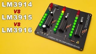
Qui invece un video dove metto a confronto gli LM3914/ 15 e 16. Tutti con lo stesso circuito ed input: ua-cam.com/video/7avb905F-MQ/v-deo.htmlsi=5hh-4HkM1tGto1b0
Versione su breadboard: ua-cam.com/video/5tI8b_KqdrM/v-deo.htmlsi=pDwHd80tnnnpcU-G
@@Stefano91ste Mi potresti dare un mano che sono un tantino "nabbo" di elettronica nel senso che non sono in grado di calcolare i componenti.
Vorrei fare questo vu-meter ma con 12 led per canale uscita a bandiera, posso chiederti un consiglio/aiuto ?
Non so se basta collegarli in serie o parallelo o serve un trasistore per amplificare la corrente, perché se non ho letto male dal datasheet dei lm39xx reggono massimo 30 mA e non credo che possa reggere la corrente di 120 led ciascuno IC.
Io ho anche pinerest eventualmente potresti passarmi uno schemino da la, se vuoi 🙂
Where can i buy the PCB Board?
Hi, from JLCPCB ( jlcpcb.com )
On your components listed above you show a quantity of four 2.7KΩ Resistors wouldn't be five ? Just wanted to make sure. love your videos. thanks for taking the time to produce them.
You are right, now I have corrected! - my fault, I made the parts list by going from memory.. thanks
I'm building this and I'm confused about the fifth 2.7k resistor, I can't find it :/ I can only see 4 in the diagram. Sorry if it's a dumb question. Also, I can only see 2 1k resistors instead of 3.
@@rafaelnieves8443 Rafael, If you look at Stefano VU Meter Board there are Five 2.7K resistors. 3 of them are directly below the LM3915 Chip on the right and the two remaining 2.7K resistors are directly below the LM3915 chip on the left. Red-Violet-Red-Gold 5% +/- equals 2.7K resistance. You are right as for the schematic. you may be able to build it that way, but there are five 2.7 Ohm resistors on the board.
Oh so they're missing from the schematic, I'm not crazy 😅 I didn't see his actual board since I'm doing ir on a breadboard and it's a bit different. So I see one between port 7 and ground (right IC), and then one connected to port 7 and ground (left IC), another one port 6 (left), port 4 (right) and ground. Lastly, one between port 4 and 8 (left IC) Which one is missing? I referenced the schematic at 0:50 to build the circuit btw.
Lastly, there are TWO 1k resistors right? Not three as in the list
@@rafaelnieves8443 The third 1K resistor is the one protecting the Power LED - LED which is not shown in the diagram as it is not a vital part of the circuit. it is a led connected between vcc and gnd.
HELP PLEASE ⚠️...⚠️.
I made this pcb , problem is led 1 and led 16 voltage is equal to input voltage (i am using 12v). so led damaged. another issue is , LED2 and LED 3 always ON (LED 1's voltage level always high) . except this ,VU meter working normally . what is the value of resistor you placed near jumper , as per schematic value is 10 Ohm , but your pcb looks different .. help me to fix... t
Hi, the resistor next to the jumper must be placed with a value between 10 ohm and 50 ohm, but it does not affect the operation of the circuit. To solve the problem of the first 2 or 3 LEDs always on use a 33K resistor instead of the 100K one (if this does not work, the problem could be due to a disturbance in the supply current or the amplifier outputs too high). Regarding the problem "led 1 and led 16 voltage is equal to input voltage" it can be caused by a faulty LM3915 or by some short circuit between the welds.
Next, take out the LM3915 and check for shorts between the solders.
Then test the correct functioning of the two LM3915s on a breadboard or replace them with two new ones.
@@Stefano91ste thank you for your support. i will try..🙂️👍️
keep me updated
Just ordered new LM3915 ICs, waiting for that. same time I am doing some experiments. I used resistors for LED1 and LED16 voltage dropped and working normally .As you said i replaced 100K resistor with 33K so LED2 and LED3 always on issue solved . but LED 1 always on.. but its ok.. I have noticed one thing , while playing music , in DOT MODE LED1 and LED11 not turning off completely . anyway I will continue..................... 😎️
Bro, why you use too many jumpers on PCB, that's double sided PCB right?
Hi, because I didn't want to make a 4 layer PCB or even enlarge this
@@Stefano91ste OMG, actually you can design the 2 layers PCB for that circuit without any jumpers.
Can you share the schematic? Thanks
Hi, you can see it in the video at 0:37
Onde comprar este produto, moro no brasil
Hi, You can download the PCB file and order the boards on jlcpcb as I show in the video.
Hola, Puede descargar el archivo de PCB y pedir las placas en jlcpcb como muestro en el video.
Can I use it for rpm on motorcycle?
Yes, but with this diagram and LM3914 prefer: ua-cam.com/video/Kowv-nJnX7o/v-deo.htmlsi=jgt_C9HD94784AmU
@@Stefano91ste thanks ❤️
Dimensões da placa?
Hi, 42x141 mm
💐💐💐💐💐
Board dimensions?
Hi, 141 mm* 42 mm
Upload pcb layout in pdf
I no share PCBs in pdf format because they are easily editable
Nice PDF Sir please
Hi, I no share PCBs in pdf format because they are easily editable