
Вставка
- Опубліковано 11 лип 2024
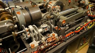
- This video shows the teardown, the reverse engineering and the test of a radio altimeter TRT AHV.5-221 which was used in A300 aircraft.
00:00 - Intro
01:05 - Teardown
06:03 - Non-linear scale
08:21 - Tests
09:34 - ARINC 552
11:00 - Reverse Engineering Part 1: Main circuits
14:11 - Reverse Engineering Part 2: Flag circuits and power supply
15:40 - Reverse Engineering Part 3: Decision Height circuits
Technical details
This Radio Altimeter is compliant with ARINC 552 standard.
The servo control loop uses a potentiometer for the feedback and a DC motor for the drive of the tape. The input is a differential DC voltage. The error voltage (feedback voltage - input voltage) is fed to the servo amplifier. The servo amplifier has a special feedback which permits to compensate partially the series resistance of the DC motor. This permits to have a control of the speed of the motor which permits a damping of the control loop.
Connector pinout:
A-B: 26Vac 400Hz
L : signal ground
Y : signal input (+)
Z : signal input (-)
a-L : Test push button
D-g : 5V lighting
e-f : relay contact for decision height (closed when the altitude is below the DH)
Useful links:
Burr-Brown document: Control a DC Motor without Tachometer Feedback
www.ti.com/lit/an/sboa043/sbo... - Наука та технологія


Thank you; excellent presentation. Old-school linear designer here who while with TI authored the last RKT (retrofit kit) for the Panavia Tornado LRU 1 (Proc/computer) test set, a three-bay rack that contained six (6) large wire wrap boards that contained a variety of electronics to interface and create test signals for the LRU 1 being tested. Also along with others authored the LUR 1 self test code that ran on the associated TI 960B minicomputer that drove the LRY 1 test set test sequences.
Very interesting and informative, the external link was useful too. I liked the schematic presentation with the pointers as well.
merci Michel je suis toujours émerveiller par la qualité de montage de ces appareils et par vos explications un grand merci pour le partage c'est a chaque fois un réel plaisir.
I love that style of PCB manufacture. Dense tru-hole layout, no soldermask, tin or silver plating and all flux removed. I have seen that alot in really expensive 70s devices. Super reliable, easy to repair and no sign of age after 50 years. I am trying to recreate that style of PCB for my homemade PCBs. I am still struggling with the tin plating, but silver plating works really well instead. Does anyone know how they tin plated those PCBs?
i love this vedio nice☑
The gate should be 2500ft AGL not 2400ft.
The tape starts at 2450ft.
Normally the older aircafts with these types of radio altimeters give a Peep tone at 2500ft AGL with a certain frequency before the tape starts to roll.
Off course it is all customer option.
Instead of a Peep tone you might hear TWENTY FIVE HUNDRED or TWO THOUSAND FIVE HUNDRED or RADIO ALTIMETER.
There is only one aircraft that I know that has a different trigger.
The Boeing McDonnel Douglas C-17 Globemaster III.
The trigger starts at 5000ft AGL.
Offcourse the RA is digital.
Most aircrafts start at 2500ft AGL.
Belle annalise , il doit y avoir un E/R associé à cet indicateur, qui serait également intéressant à étudier.👍
Я думал, что будет показан радиочастотный тракт... А тут всего лишь индикатор, который управляется напряжением.
That is a beautiful instrument! I learn so much from the reverse engineering you share. It is interesting that this instrument provided filtering of the flag circuit for the servo error comparator but it does not appear there is any filtering of the pin M 28VDC "valid" from the radio altimeter...do I undertstand that correctly? I also really appreciate that explanation of how the linear to logarithmic transition is made for the ARINC 552 curve. Really fantastic video, thank you.
I don't know how the valid signal is generated inside the radar Tx/Rx unit but I guess that this signal is stable. The system works or not. Concerning the servo control it is different, the flag would appear when there is a large change of altitude during a certain time because in that case the servo control is not stabilized. I think that this filter is present to avoid such effect.
Осциллограф у вас хороший