Latches and Flip-Flops 4 - The Clocked D Latch

Вставка
- Опубліковано 13 сер 2016
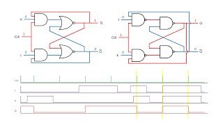
- This is the fourth in a series of videos about latches and flip-flops. These bi-stable combinations of logic gates form the basis of computer memory, counters, shift registers, and more. In particular, this video covers the clocked D latch, that is, a D latch controlled by a computer clock signal which is important for synchronisation. It shows how an edge detection device can be built from a NOT gate and an AND gate in order to isolate the rising edge of the clock cycle. It then shows how this can be used to turn a level triggered D latch into an edge triggered D latch - the so called pulse latch. The asynchronous inputs PRE and CLR in a clocked D latch are also mentioned. The video that follows this one builds upon the principles covered and goes on to describe the master slave D type flip flop.


Teacher takes 3 weeks to explain this...i don't understand
I spent an hour watching your series and i know every little detail. Thanks a bunch!
I love it when the light bulbs switch on :)
that...made my day :D
✊👨🏽💻🤭🙋♂️me too
tears rolling through my eyes because you explained it so well.
The likes to dislikes ratio says is all. Your 5 videos on latches and flip flops are just perfect. The time you take to explain it all, the detail, everything. You are saving my grades, thank you!
Thanks for taking the time to comment. It keeps me at it. :)KD
Ahh, how I miss the good ol' days when the dislike number was visible to the average viewer.
This video deserve way more views than It has currently.
Please keep it up
Best on flip flop I found on UA-cam.After watching series on flip flop I understand what I was looking to understand for last two year.
This (you) are the third teacher to me on this subject. You hit it out of the park. Especially with the addition of the timing lines after explanations.
Delighted to help. Thanks for the comment :)KD
This is amazing... I never realized that edge detection naturally arises from static hazard! You are such a good teacher!
you saved me from the test!! There are also videos on my school's website, I swear I have watched 5 times but I still don't understand, and you did it. thanks a lot!!
Tnx. I appreciate your comment.
Just a heads up these are still being watched and appreciated--shared this with my study group and saved us from the finals. Thanks!
That's great to hear. Tnx. :)
Still being watched and appreciated in 2021! I however, am just a layman who likes to understand how things work.
One of the series of videos giving clear and simple explanation about latches and flip-flops! Great job!
Hah gosh bless you, sir. That explanation on "triggered D latches" saved me. Specifically, I've been wracking my brain about why "shift registers" don't race all the way to the end while the clock is on and no one explained why. That small comment about "edge detection" finally explained that seemingly irreconcilable error. I'm so glad that you brought it up
Thanks for the lovely comment. I'm glad to be of use.
Such a great series on latches and flip-flops. Thank you very much for the content!
Incredible, I just started my B.Sc. and your videos are beyond just helpful! Thank you so much for all the great explanations! :)
That's lovely to hear. Tnx for the comment.
Amazing! Week 10 of 13 in Aus, and this makes SO much more sense than our lecturers! 👏
I normally never comment but had to make an exception for this set of videos. Very concise explanations. The timing diagrams were very helpful! Thank you!
Delighted to help. Thanks for the comment. :)KD
I'm a first year CS student and man these explanation videos and your channel help me so so so damn much. Can't put it in words. I specifically look up if you've made videos whenever I get stuck on a certain topic or want to learn one. You're godsend. Power and health to you.
You are most welcome. I'm delighted to be of service :)KD
This playlist and the way it is explained is greatly appreciated. I am a green tech, and this really helps to
reaffirm my understanding of gates/latches/flip flops/counters/shift registers....ect... this is helping to
build the foundation that I need move ahead. Thank you so much.
Thanks! Your videos about latches and flip flops are the only I could finally understand!
Brilliant little series of videos, thanks for sharing
Thanks for commenting. You are most welcome :)KD
This series is saving my life right now.
Glad to help. Tnx for the comment :) KD
I literally logged in only to like and comment on this video. This latches and Flip-Flops series is probably some of the best educational stuff on here! You need more recognition! Keep up the good work!
You, sir, are a lifesaver! Subscribed!
Your videos are incredible! Thank you so much!
Thanks for saying so - really appreciated.
I've been building Ben Eater's 8-bit computer, and while his videos are excellent, your timing diagrams with the moving yellow bar are really helping things click for me. Thanks so much for including these!
Delighted to help. I built an 8 bit computer too and it's all over my wall :)KD
Crazy good video series. More please.
It's just like watching the Open University courses back in the 80's. Just focused on the facts and the knowledge. Just outstanding.
Excellent series of videos!!!
Is there a patreon we can use to help aid these videos?
best explanation i have ever got!!
Your videos are really helpful, thanks a lot!
Thanks. I appreciate the comment. K:D
Such a nice video! Thanks a LOT!
Thank you so much for your Videos! They making my hardware class way simpler for my Comp sci degree!
You are very welcome. And thank you :)KD
This is clean as hell.
:)KD
This explains in a very simple way to understand!!! Save me from lectures! Keep it up. ~Engineering Student
very epic video my dude understood everything
You are amazing!
Thank you for the video! Helps me so much with my classes
You're welcome
i got it now.....my teacher never said a D FF is a clocked latch, that was the reason to why i was confused...Thanks a lot
Sadly, a number of text books confuse the D type flip flip with other types of latch. :)KD
bruh these videos are so goooood
Thanks a million :)KD
quality teaching!
Great explanation
Thank you
The only comment I have ever made on a youtube video, You sir, are a saint. Sad universities only hire big worded, small-brained academics.
K. I. S. S. :) KD
thank u a lot kevin
thank you very much!
You're most welcome :)KD
Thank you
Respect!
Many thanks :)KD
:)
You sir are way better than my professor! Thank you!!
Splendid
You're welcome :)KD
I absolutely love this video and the rest of the videos you've made on boolean algebgra, karnaugh maps, and cryptocurrency. (though I haven't studied that yet)
Though I do have a question. If preset and clear are both 0, doesn't this create a race condition?
Yes but only briefly. Inconsistencies in the manufacturing mean that soon enough a latch will settle into a stable state.
i dont curse but uuuhhm....... yea, kudos to you sir. THIS IS BRILLIANTLY FUCKING WELL CONSTRUCTED, STRAIGHT TO THE POINT, NICELY DONE EXPLANITION OF THIS STUFF. We need teachers like you
i think this is used for sequence combination, where the inputs need to be sequentially inputed, ihope yuu can do a video on making sequence combination circuit which can be used for locking
I love you my lord.
thanks a lot!!!!!!
You are welcome. :) KD
saving my life bro
Glad to help :)KD
What happens if the edge detector goes back to zero before the latch has managed to change states? Aka what happens when the time interval that the edge detector allows current to flow through is less than the propagation delay of the latch? Would that mean that the state of the latch will not change? (I have watched the 5th episode of the series)
legend
Thank you :)KD
I have a question if you could kindly answer it would be very helpful.
What happens if PRE and CLR are both set to 0 ?
Hi sir , I am from india and You have no idea how beautifully you have dissected the whole topic and presented in such a meaningfull way. Many other videos are so horribly wrong were they are giving clock pulse directly to enable pin of series shift register and I was soo confused on the durations of individual clock pulse . But still one questions is still prevailing in my mind that what causes that delay or data persistence in not gate out put inspite of the fact that input signal is been changed???
thanks
You're welcome. :)KD
what happens if you don't want to change the value in the D latch every clock cycle? What if you only wanted to change it on a certain clock cycle?
thanks daddy. this rlyylyly helped ima pass my class (-:::::
Is there any functional difference between this clocked D latch and a D flip flop?
Yes. As you can see in the next video of this series. :) KD
9:30
I can understand that :
1. Making clear = 0 means that one of the inputs of the bottom right NAND gate is 0
2. So that gate will output 1
3. So Q' = 1
Which should mean that Q = 0, but how can ee see it. I do not see how making Q' = 1 would make Q = 1.
Maybe it has something to do with the clock at that time? :(
For the PRE and CLR, how can the NAND have 3 inputs?
Hi Elgs Chen. A NAND gate can have 3 inputs. You can even have a 4 input NAND function (which is actually several 2 input NAND gates combined together). Take a look at www.electronics-tutorials.ws/logic/logic_5.html The important thing about a NAND gate is that only when ALL inputs are high the output will be low.
Thank you Kevin! I cannot express how much I appreciate your effort making these concepts so clear and easy to understand. I watched a lot of other videos and I had never really understood what they were talking about.
@@elgs1980 Kevin? Hummmmm.
Waaaaaaait a minute. At 4:48 when a high signal is coming out of the not gate, and then takes a high input, “there is a brief period where both input and the output of the Not gate are high, and therefore the output of the AND gate is high.” But if there is some kind of propogation delay in which both the input and output of the NOT. gate are high, wouldn’t this be cancelled out by the propogation delay for the OTHER input of the AND gate’s signal to reach the output? If the NOT gate has a delay, that briefly keeps both input and output high, why doesn’t the AND gate’s input have a corresponding delay that keeps it’s output low?
Answering my own question: By putting more NOT gates in series. By creating a big enough odd number of NOT gates in series, their cumulative propogation delay relative to the other straight input signal of the AND gate, would create a pulse width from the clock long enough to measure, but at some point there will a point, where a single NOT gate would not create a propogation delay long enough to not be cancelled out by the propagation delay of the AND gates’s input. Two NOT gates’ delay can be measured; one NOT gate, not so much. That’s my guess anyways.
Take a look at the master slave D-type flip flop
Second High output Q is a bit wrongly displayed at 2:40. It may perplex the viewers.
D is high, clock is high, Q is high. I believe it's correct.
Yes, It is right that D is High, E (clock) is High, but these are High in the pattern of 100 whereas Q is High in 111? Please elaborate if I miss anything. Regards.
That means D & Clock is High only once , then Low Low: whereas Q is High High High.
😘😘😘😘😘😘😘😘😘😘😘😘😘
TY :)KD
why not make E 1 all the time sir,,, thanks a lot
I heard a puppy in the background at 1:30 a little after he says the word “clock
Probably the neighbour's the Irish wolf hound; I have a cat.
this its not the reduced and more stable version of a d flipflop
This is ridiculous... I spend 14 grand for college and this youtube video is 100x better, and its free...
I should set up a college. :)KD
@@ComputerScienceLessons Just curious, are you Christopher?