Thanks for watching. For more Op Amp Circuit examples pls see: Op Amp Amplifier with Electronic Gain Control ua-cam.com/video/NoNgQpbj77Y/v-deo.html Push-Pull Power Amplifier with Darlington Transistors ua-cam.com/video/866MYibo8yE/v-deo.html Voltage Regulator Op Amp Circuit with Foldback current limiting ua-cam.com/video/VN4_qF9DvBM/v-deo.html Power Amplifier Design (Class A) with Transformer ua-cam.com/video/gKlJrqGqeCI/v-deo.html Current Foldback Voltage Regulator Circuit Design with Op Amp, Darlington BJT Transistors ua-cam.com/video/RFfRrbqM_-s/v-deo.html Analog Logarithm Computer ua-cam.com/video/RpKEq5WyoLg/v-deo.html Op Amp Analog Computer Differential Equation Solver ua-cam.com/video/ENq39EesfPw/v-deo.html Thermometer Circuit Design with Op Amp & BJT transistor ua-cam.com/video/55YsraFE0rg/v-deo.html Instrumentation Amplifier with Electronic Gain Control ua-cam.com/video/C4tghZ-q6Zs/v-deo.html Sallen-Key Analog Filter Design Tutorial ua-cam.com/video/KwUnQXbk7gM/v-deo.html Universal Analog Filter Design ua-cam.com/video/2J-0msXZE2o/v-deo.html Laplace Transform Example and S-domain circuit analysis: ua-cam.com/video/ps8N5TPM_qU/v-deo.html Op Amp circuit Bode Frequency plot ua-cam.com/video/BLVzuuqAlZs/v-deo.html Lowpass Butterworth Filter: ua-cam.com/video/UzCjkwqy-9w/v-deo.html Analog Computer to Raise Signal to power n ua-cam.com/video/IUTlBH1UraE/v-deo.html Triangle Oscillator Op Amp circuit ua-cam.com/video/JF5Up_cuL9k/v-deo.html Differential Equation Solver Analog Circuit ua-cam.com/video/R3X5AYNZGEI/v-deo.html Complex Sinusoid Oscillator ua-cam.com/video/GXRhmwmS5Zk/v-deo.html Sawtooth Oscillator Design ua-cam.com/video/2eUsGPfqbW4/v-deo.html Full-Wave Rectifier circuit example ua-cam.com/video/DJJMNU-CYcg/v-deo.html Sawtooth Waveform Generator design with OpAmp, JFET, BJT ua-cam.com/video/5zHXTx-Vl20/v-deo.html op amps Circuit with feedback loops to design an analog computer that solves a second order differential equation ua-cam.com/video/HeZRtnRXpEI/v-deo.html For more analog circuits and signal processing examples see: ua-cam.com/play/PLrwXF7N522y4c7c-8KBjrwd7IyaZfWxyt.html I hope these Circuit design and analysis videos are helpful. 🙋♂
Thank you for your kind words! I'm glad to hear that you've found the series helpful and that the explanations are making a positive impact on your learning. It's great to know that the practical design insights are proving valuable to you! I think you'll also find the related video ua-cam.com/video/866MYibo8yE/v-deo.html on the Push-Pull Amplifier with Darlington and Sziklai Transistors interesting as it explores a similar concept using different transistor configurations with more examples in the ua-cam.com/play/PLrwXF7N522y4vWr-8XRBqxpi5idFDE9BV.html Power Amplifiers & Voltage Regulators playlist where you'll find a variety of related circuits and explanations. I hope you find these videos interesting as well as you explore more in-depth analog circuit design.
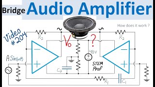
A nice Sziklai Darlington circuit, but I have some stability doubts. The first one is, Op Amps normally need capacitors at the supply rails to avoid random phase shifting of the internal components (e.g. current source of the differential amplifier). A phase-shift close to π turns every amplifier with feedback into an oscillator, resulting in magic smoke from the power transistors. Already a typically used 220nF capacitor with R3=70Ω results in maximum a frequency of 10.3kHz (-3dB-point) - instead of 20kHz due to τ=RC and fo=1/(2πτ). The second issue is the stability of the bias current to suppress crossover-distortions. Since BE-voltage of a BJT drops about -20mV/K according to the Shockley-equation, I can't recognize a stable and temperature compensated bias. In my power-amplifier designs I regularly use a either two diodes and a variable resistor, or a BJT with a variable resistor, thermally coupled to the power transistors. This ensures a stable bias-current over the whole intended operation temperature range.
Thank you for watching and sharing your insights and practical suggestions. You have good points for practical implementations. For the capacitor at the supply rail for the op amp, the adjustment in scaling down value of R3 to say 470 ohm and op amp supply rail cap to 150nF should be practically safe to allow for 20KHz 3dB cutoff frequency. As for the thermal stability, you have good points. That is an important topic that should surely be considered for practical implementation. There are multiple techniques including the methods you mentioned. For more examples involving temperature measurement and compensation please watch: Voltage Regulator with Temperature Compensation ua-cam.com/video/NdfyHoxjKrY/v-deo.html and Anti-Log Analog Computer with Transistor-Tempco Resister Temperature Compensation ua-cam.com/video/kk2c7Gk3nW4/v-deo.html Thermometer Circuit Design with Op Amp and BJT transistor ua-cam.com/video/55YsraFE0rg/v-deo.html Thanks again 🙏
You are welcome. Thanks for watching & your encouraging comment. I'm glad that you like this Push-Pull Power Amplifier Circuit Design video. If I get the chance I'll present Spice simulation. For more analog circuits & Op Amp examples see: ua-cam.com/play/PLrwXF7N522y4c7c-8KBjrwd7IyaZfWxyt.html I hope these Circuit design & analysis videos are interesting.
@@nataphongthip You are welcome. Glad that this Push-Pull Power Amplifier video is helpful. Another example is Push-Pull Amplifier with Darlington and Sziklai Transistors ua-cam.com/video/866MYibo8yE/v-deo.html More analog circuits & Op Amp examples are in the Power Amplifiers & Voltage Regulators Video Playlist ua-cam.com/play/PLrwXF7N522y4vWr-8XRBqxpi5idFDE9BV.html I hope these Circuit videos are interesting as well.
For me to have a good result, we need another really good sounding input opamp and a common negative feedback loop. Because all these "special" (high voltage) opamps are total cr.. considering how do they sound. Another thing is a setting of a bias on the output transistors. I think the opamp output resistor can do this. It must be small. The third thing is a stability. Shiklays are not good in this. Must be simulated, prototyped and tested.
I would have liked to see a emitter resistor on the power transistors and a bios circuit wit temperature correction and a always on resistor for the drivertransistors so we don't get crossover distorsion. And I don't understand the 9 ohm load - it should hav bee 8 ohm (will acquire no changes) og 4 ohm. But a very good review of the circuit. I don't think you need to worry so much about Vi+ = Vi- it must be expected that we know that. Thanks!
Thanks for watching and sharing your thoughts regarding practical considerations. Depending on application designer need to properly select op amps and power Transistors. (I just presented examples). A variant of this design with Darlington Transistor IC package instead of discrete Sziklai transistor pair might be a better choice. For more examples please see Op Amp Amplifier with Electronic Gain Control ua-cam.com/video/NoNgQpbj77Y/v-deo.html Push-Pull Power Amplifier with Darlington Transistors ua-cam.com/video/866MYibo8yE/v-deo.html Power Amplifier Design (Class A) with Transformer ua-cam.com/video/gKlJrqGqeCI/v-deo.html For more analog circuits and signal processing examples see: ua-cam.com/play/PLrwXF7N522y4c7c-8KBjrwd7IyaZfWxyt.html I hope these Circuit design and analysis videos are interesting. 🙋♂
Thanks Michael for watching & sharing your observations & your feedback. Glad that this power amplifier example is useful. As a variant of this design we can move the current limiting resistor to emitter of power transistor that then requires modifying current limiting BJT transistor as well. We can also replace Sziklai Transistors with packaged Darlington BJT IC. I also understand your point regarding 8 ohm. My main focus was on the explanation of how the power amplifier circuit works and how to design it. I also appreciate your point regarding the basic level of virtual short for op amp. But please notice that I have to consider a wide range of audience and therefore I try to start with first principles in the circuit analysis that sometimes require repeating basics. I hope this clarification is helpful. For more analog circuits and signal processing examples see: ua-cam.com/play/PLrwXF7N522y4c7c-8KBjrwd7IyaZfWxyt.html Thanks again 🙋♂️
@@STEMprof Yes, I see. Your "explanation series" is outstanding, and will be referenced for a long time in a future I hope. Besides it contains "tricky" examples, and this is great. Good luck with your channel, sir.
@@sc0or You're welcome, and Thank you for the encouraging comment. Glad that you like my channel and its videos are useful. Thanks again for sharing your thoughts 🙏
Very interesting schematic. I'm missing one thing, how to determine value of output resistor for that opamp? I would proceed this way: define max allowable current of opamp (say 30mA in this case), if output is shorted then max voltage would be 35V. So value would be 1.2 kΩ. Or I have to consider full span ±35V (in case there is some capacitance at the output and charged to -35V), so the value would be 2.4 kΩ. Or there is something else to consider?
Thanks for watching, your comment and sharing your thoughts and good practical suggestions. As you pointed out, the presence of that resistor at the output of the OpAmp is exactly to protect the op amp by limiting its output current. You summarized it well to compute the resistor value taking into account the worst case scenario of max op amp output voltage while load is shorted to ground. A value on the order of 1kOhm should be fine given nominal output AC current of the op amp is on the order of mA or less in this design (since power BJT transistors are sourcing or sinking current). For more Op Amp Circuit examples pls see: Op Amp Amplifier with Electronic Gain Control ua-cam.com/video/NoNgQpbj77Y/v-deo.html Push-Pull Power Amplifier with Darlington Transistors ua-cam.com/video/866MYibo8yE/v-deo.html Power Amplifier Design (Class A) with Transformer ua-cam.com/video/gKlJrqGqeCI/v-deo.html Analog Logarithm Computer ua-cam.com/video/RpKEq5WyoLg/v-deo.html Op Amp Analog Computer Differential Equation Solver ua-cam.com/video/ENq39EesfPw/v-deo.html Thermometer Circuit Design with Op Amp & BJT transistor ua-cam.com/video/55YsraFE0rg/v-deo.html Instrumentation Amplifier with Electronic Gain Control ua-cam.com/video/C4tghZ-q6Zs/v-deo.html For more analog circuits and signal processing examples see: ua-cam.com/play/PLrwXF7N522y4c7c-8KBjrwd7IyaZfWxyt.html Thanks again🙋♂
I have a hard time understanding where the 'control' of the circuit comes from. The output of the OpAmp alone cannot move the RL, isn't? The only defining fact is the Ube on T2 (and T4 for the bottom side), which is ever so slightly on. I can only figure, that the OpAmp might need more current flowing into the Vdd if the output swings positive and thus creates a current over the Rout. After all this current has to come from somewhere, so it's likely from Vdd? Or IR3 into Vss for the negative half wave. But that would also mean, that this circuit cannot work anymore once you go for a TL072 or any other dual OpAmp? Is this correct or what do I miss? Also the biasing might require the two R3s to be trimmers in the real world? txs and please keep posting such excellent videos!
Thanks for the encouraging comment. Glad that you liked my videos. Regarding your question, as you already well summarized, the internal output stage inside the op amp looks similar to the NPN-PNP output stage of this power amplifier circuit (albeit with orders of magnitude less current). During the output positive swings more current flows from the Vdd toward the positive supply rail of the op amp resulting in voltage drop across resistor R3 that then turns on the PNP transistor of the Sziklai PNP-NPN pair. Regarding Op Amp, I suggest Texas Instruments OPA607 or TL071 single op-amp package to avoid issues. And regarding your trimmer question, it should add further flexibility assuming a proper resistor value for the range of trimmer. For more examples please see: Push-Pull Power Amplifier with Darlington and Sziklai Transistor pairs ua-cam.com/video/866MYibo8yE/v-deo.html and High Voltage Push-Pull Power Amplifier design ua-cam.com/video/C9Hse91r5sA/v-deo.html I hope the explanation and examples are helpful.
Could it be better to re-considered this circuit?: ..Perhaps better to have the OpAmp feed towards the upper&lower sziklay-pairs instead(also make some biasing for the first transistors of those), ..And also perhaps removed both the R3's (that potentially can interrupt stable Vcc/Vdd for the OpAmp).. /The upper&lower 'clamping-transistors' seems like a fine concept (not referencing towards them, they seem Ok). Have nice week, thanks for sharing interesting electronic ideas. Electronics is a very fine hobby for many people.
www.youtube.com/@rolfts5762 You're welcome. And thanks for sharing your thoughts and good suggestions. To your point, there are many alternative ways and techniques to design and later this power amplifier circuit especially taking into account practical design considerations. For more stable high power amplifier designs I would recommend the following videos: ua-cam.com/video/866MYibo8yE/v-deo.html designing a Push-Pull Power Amplifier with Sziklai/Darlington Transistor pairs, ---------- and also ua-cam.com/video/C9Hse91r5sA/v-deo.html video of High Voltage Push-Pull Power Amplifier design with Op Amp and Darlington Transistors. Hope these are interesting as well.
Thanks for your interest in this channel. My suggestion is first identify the most appropriate operational amplifier for your specific application considering your desired KPIs (gain-bandwidth, slew rate, output current , supply range, etc.). Then if the output impedance of your selected op amp is not as low as you want, you can use one of the resistive load reduction techniques (for example add a negative resistance at its output of op amp). For more analog circuits and signal processing examples see: ua-cam.com/play/PLrwXF7N522y4c7c-8KBjrwd7IyaZfWxyt.html I hope this is helpful. 🙋♂
Thanks for watching and your interest in this Push Pull Amplifier Design video. Glad that that you liked this circuit. For more amplifier examples please see ua-cam.com/play/PLrwXF7N522y4c7c-8KBjrwd7IyaZfWxyt.html. For Audio Amplifier Design practical consideration and THD of transformer parasitics and non-idealities including imperfect flux and magnetic coupling are important in order to achieve a decent functional design with acceptable in-band frequency response (say 20 kHz for audio applications). To achieve that an important step is properly selecting (with correct voltage) Audio Transformer or Signal Transformer that can be purchased from either www.digikey.com/en/products/filter/audio-transformers/162 or www.mouser.com/c/passive-components/audio-transformers-signal-transformers/. That proper selection should ensure a practically flat-response transformer in the desired frequency range. I will post more examples in my analog circuits and signal processing playlist: ua-cam.com/play/PLrwXF7N522y4c7c-8KBjrwd7IyaZfWxyt.html I hope this is helpful.🙏
@@STEMprof accidentally watching this video again, because it showed at some guy explaining guitar amp. 18:22 The current coming from the base of "t1", next to R3 is heading to Rx / PNP power transistor emitter. but the NPN with the same function on the low side doesn't have this problem, wouldn't that offset the output of the circuit? I was playing with the Sziklai config in the simulator for logic and driving leds, i was forgotten about this video and thought i rediscovered the whole thing. : ) I decided to build an amp with the Sziklai config in the sim, i use 4 opamps (TL074) to completely eliminate zero cross distortion. couple of days ago, i got some BD137 & BD140 transistors from the shop around the corner and couple of weeks ago i got the +/-15V transformer this guy reserved for me, it's New Old Stock thing. I think you would like my design, however more "research" is needed, before i send out the PCB file. I'm also designing a simple function generator to create a Triangle, to test my amp with frequencies of 100kHz or more, i saw someone do that with a Chinese clone of DarTZeel amplifier and it started to drop in amplitude at frequencies well over 200kHz. But i still only have +/-15 V toroid transformer witch aint even symmetrical 40va, 10va, playing with the resistors on the base of the Sziklai's i can easily max out the BD137, BD140 of 1.5 amp at 15V in the sim, witch voltage swings of about 20 V.p.p., even at 3 V.p.p. How does that work with car's amplifiers witch only have 12V, max 13.5V? I can't use Rx, i would need power transistors witch i don't have, but i'll try to shoehorn these protections transistors somehow.
@@AnalogDude_ Glad that you rewatched this video and revisited my channel. Thanks for sharing your insights and observations. There have been few changes in channel structure. There are now smaller focused circuit playlists including Oscillators (Triangle, Sawtooth and Complex), Amplifiers and sensor signal conditioning videos (links below). Regarding the current coming from the Base of T1 transistor, it actually goes to the collector of the NPN power transistor. Oscillators & Signal Generators ua-cam.com/play/PLrwXF7N522y4ee_0GL2EdguM-kLtJPxpU.html Sensors & Instrumentation Amplifiers ua-cam.com/play/PLrwXF7N522y7Ut9bm8TXAOhIWqL__FGlj.html Power Amplifiers & Voltage Regulators Videos ua-cam.com/play/PLrwXF7N522y4vWr-8XRBqxpi5idFDE9BV.html I hope you find these more focused Circuit Videos playlists helpful.
@@STEMprof I'm trying to do the same with mosfets in the Fallstad simulator, the source of the N-type via resistor is connected to 1.5 Volt, so if the amplitude of the audio exceeds this limit the mosfet starts working, something like a audio compressor. it kinda works, but not there yet.
In this way you can increase the maximum current of the OP-AMP but not the voltage which for a Ne5534 is 44 volts max. Perhaps you can try to increase the maximum current that can be driven by a TDA2052 (or similar), but you can hardly find something larger than 44 volts on the OP-AMPs market. Do you want to design an op-amp with discreet components? Greetings from Italy and good luck
Thank you for sharing your thoughts on this circuit and op-amp. Please note that the op-amp's maximum allowed supply voltage is not violated in this design. The additional voltage drop across the series resistor in the supply rail will accommodate the extra voltage drop. On a separate note, there are indeed high-voltage operational amplifiers with push-pull output stages. An example is the Apex Microtechnology PA198 High Voltage Power Operational Amplifier, which delivers output voltages ranging from ±215V with a dual supply to +440V with a single supply configuration. For more information, see the APEX PA198 datasheet at this link www.mouser.com/pdfDocs/pa198u.pdf Additionally, you can find more examples of power amplifiers in the ua-cam.com/play/PLrwXF7N522y4vWr-8XRBqxpi5idFDE9BV.html Power Amplifier and Voltage Regulator Video Playlist. I hope this is helpful!
Ok, Opa443 .... But there is a problem with noise in all of them.... ~20 nV/√(Hz) with amplitude from 1V to 60V max all that noise becomes ~1200 nV/√(Hz). In comparison to normal low noise audio OpAmps with noise below ~4..5 nV/√(Hz) Some of them even near only ~1 nV/√(Hz) But all of them have ±18V max. What to do if we need to get low noise 50W power amplifier?
Thanks for your interest in this Push-Pull Power Amplifier Design example. Yes, OPA443 is a high-voltage +/-40V Rail operational amplifier. Careful selection of Op Amp is important in high power amplifier design. For another example see Push-Pull Power Amplifier with Darlington and Sziklai Transistor pairs ua-cam.com/video/866MYibo8yE/v-deo.html
@@Arwndr Thanks for watching & sharing your thoughts. You have a good point. Noise, drift and input offset are all valid and important concerns in op amp based circuit designs. A good designer need to identify the right operational amplifier that satisfies a practical balance among conflicting set of requirements including cost, power, Noise, drift and input offset. If need be a proper Filtering stage possibly additional feedback might be needed at the input or output of the circuit to further control or remove noise. Here is another example ua-cam.com/video/C9Hse91r5sA/v-deo.html which is a Push-Pull Power Amplifier design (High Voltage) with Op Amp and Darlington Transistors.
@@STEMprof Thank you for big open feedback, and links for another solutions. I will study them all. Also, us I understand, to much of feedback filtering for reducing Noise, - also reduce some parts and pieces of original audio. That's why I look for less noisy components where it possible, so to not create an extra problems with Noise so to have less deal with it in post, with some inevitable concomitant quality loss of original audio source. Thanks for your channel! Very helpful for self education 🙌🏻👍🏻👌🏻🤝🏻
You're welcome. Glad that this video is useful. More Power Amplifiers Videos are posted in Power Amplifiers & Voltage Regulators Plalist: ua-cam.com/play/PLrwXF7N522y4vWr-8XRBqxpi5idFDE9BV.html
Thanks for watching. I'm glad that you like this Push-Pull Power Amplifier Circuit Design video. For more analog circuits & Op Amp examples see: ua-cam.com/play/PLrwXF7N522y4c7c-8KBjrwd7IyaZfWxyt.html . I hope these additional Circuit design & analysis videos are interesting as well.


Thanks for watching. For more Op Amp Circuit examples pls see:
Op Amp Amplifier with Electronic Gain Control ua-cam.com/video/NoNgQpbj77Y/v-deo.html
Push-Pull Power Amplifier with Darlington Transistors ua-cam.com/video/866MYibo8yE/v-deo.html
Voltage Regulator Op Amp Circuit with Foldback current limiting ua-cam.com/video/VN4_qF9DvBM/v-deo.html
Power Amplifier Design (Class A) with Transformer ua-cam.com/video/gKlJrqGqeCI/v-deo.html
Current Foldback Voltage Regulator Circuit Design with Op Amp, Darlington BJT Transistors ua-cam.com/video/RFfRrbqM_-s/v-deo.html
Analog Logarithm Computer ua-cam.com/video/RpKEq5WyoLg/v-deo.html
Op Amp Analog Computer Differential Equation Solver ua-cam.com/video/ENq39EesfPw/v-deo.html
Thermometer Circuit Design with Op Amp & BJT transistor ua-cam.com/video/55YsraFE0rg/v-deo.html
Instrumentation Amplifier with Electronic Gain Control ua-cam.com/video/C4tghZ-q6Zs/v-deo.html
Sallen-Key Analog Filter Design Tutorial ua-cam.com/video/KwUnQXbk7gM/v-deo.html
Universal Analog Filter Design ua-cam.com/video/2J-0msXZE2o/v-deo.html
Laplace Transform Example and S-domain circuit analysis: ua-cam.com/video/ps8N5TPM_qU/v-deo.html
Op Amp circuit Bode Frequency plot ua-cam.com/video/BLVzuuqAlZs/v-deo.html
Lowpass Butterworth Filter: ua-cam.com/video/UzCjkwqy-9w/v-deo.html
Analog Computer to Raise Signal to power n ua-cam.com/video/IUTlBH1UraE/v-deo.html
Triangle Oscillator Op Amp circuit ua-cam.com/video/JF5Up_cuL9k/v-deo.html
Differential Equation Solver Analog Circuit ua-cam.com/video/R3X5AYNZGEI/v-deo.html
Complex Sinusoid Oscillator ua-cam.com/video/GXRhmwmS5Zk/v-deo.html
Sawtooth Oscillator Design ua-cam.com/video/2eUsGPfqbW4/v-deo.html
Full-Wave Rectifier circuit example ua-cam.com/video/DJJMNU-CYcg/v-deo.html
Sawtooth Waveform Generator design with OpAmp, JFET, BJT ua-cam.com/video/5zHXTx-Vl20/v-deo.html
op amps Circuit with feedback loops to design an analog computer that solves a second order differential equation ua-cam.com/video/HeZRtnRXpEI/v-deo.html
For more analog circuits and signal processing examples see: ua-cam.com/play/PLrwXF7N522y4c7c-8KBjrwd7IyaZfWxyt.html
I hope these Circuit design and analysis videos are helpful. 🙋♂
Love your series of video! Thanks for your detailed explanation. I learned valuable practical design from you. It is extremely interesting.
Thank you for your kind words! I'm glad to hear that you've found the series helpful and that the explanations are making a positive impact on your learning. It's great to know that the practical design insights are proving valuable to you! I think you'll also find the related video ua-cam.com/video/866MYibo8yE/v-deo.html on the Push-Pull Amplifier with Darlington and Sziklai Transistors interesting as it explores a similar concept using different transistor configurations with more examples in the ua-cam.com/play/PLrwXF7N522y4vWr-8XRBqxpi5idFDE9BV.html Power Amplifiers & Voltage Regulators playlist where you'll find a variety of related circuits and explanations. I hope you find these videos interesting as well as you explore more in-depth analog circuit design.
A nice Sziklai Darlington circuit, but I have some stability doubts. The first one is, Op Amps normally need capacitors at the supply rails to avoid random phase shifting of the internal components (e.g. current source of the differential amplifier). A phase-shift close to π turns every amplifier with feedback into an oscillator, resulting in magic smoke from the power transistors. Already a typically used 220nF capacitor with R3=70Ω results in maximum a frequency of 10.3kHz (-3dB-point) - instead of 20kHz due to τ=RC and fo=1/(2πτ). The second issue is the stability of the bias current to suppress crossover-distortions. Since BE-voltage of a BJT drops about -20mV/K according to the Shockley-equation, I can't recognize a stable and temperature compensated bias. In my power-amplifier designs I regularly use a either two diodes and a variable resistor, or a BJT with a variable resistor, thermally coupled to the power transistors. This ensures a stable bias-current over the whole intended operation temperature range.
Thank you for watching and sharing your insights and practical suggestions. You have good points for practical implementations. For the capacitor at the supply rail for the op amp, the adjustment in scaling down value of R3 to say 470 ohm and op amp supply rail cap to 150nF should be practically safe to allow for 20KHz 3dB cutoff frequency. As for the thermal stability, you have good points. That is an important topic that should surely be considered for practical implementation. There are multiple techniques including the methods you mentioned. For more examples involving temperature measurement and compensation please watch: Voltage Regulator with Temperature Compensation ua-cam.com/video/NdfyHoxjKrY/v-deo.html
and Anti-Log Analog Computer with Transistor-Tempco Resister Temperature Compensation ua-cam.com/video/kk2c7Gk3nW4/v-deo.html
Thermometer Circuit Design with Op Amp and BJT transistor ua-cam.com/video/55YsraFE0rg/v-deo.html
Thanks again 🙏
Doesn't work at all...
very nice work - congratulations on an exceptional presentation - perhaps can you present it in L spice
You are welcome. Thanks for watching & your encouraging comment. I'm glad that you like this Push-Pull Power Amplifier Circuit Design video. If I get the chance I'll present Spice simulation. For more analog circuits & Op Amp examples see: ua-cam.com/play/PLrwXF7N522y4c7c-8KBjrwd7IyaZfWxyt.html
I hope these Circuit design & analysis videos are interesting.
thank you I hope you continue to doing.
You are my teacher
@@nataphongthip You are welcome. Glad that this Push-Pull Power Amplifier video is helpful. Another example is Push-Pull Amplifier with Darlington and Sziklai Transistors ua-cam.com/video/866MYibo8yE/v-deo.html
More analog circuits & Op Amp examples are in the Power Amplifiers & Voltage Regulators Video Playlist ua-cam.com/play/PLrwXF7N522y4vWr-8XRBqxpi5idFDE9BV.html
I hope these Circuit videos are interesting as well.
For me to have a good result, we need another really good sounding input opamp and a common negative feedback loop. Because all these "special" (high voltage) opamps are total cr.. considering how do they sound. Another thing is a setting of a bias on the output transistors. I think the opamp output resistor can do this. It must be small. The third thing is a stability. Shiklays are not good in this. Must be simulated, prototyped and tested.
I would have liked to see a emitter resistor on the power transistors and a bios circuit wit temperature correction and a always on resistor for the drivertransistors so we don't get crossover distorsion. And I don't understand the 9 ohm load - it should hav bee 8 ohm (will acquire no changes) og 4 ohm.
But a very good review of the circuit. I don't think you need to worry so much about Vi+ = Vi- it must be expected that we know that. Thanks!
Thanks for watching and sharing your thoughts regarding practical considerations. Depending on application designer need to properly select op amps and power Transistors. (I just presented examples). A variant of this design with Darlington Transistor IC package instead of discrete Sziklai transistor pair might be a better choice. For more examples please see
Op Amp Amplifier with Electronic Gain Control ua-cam.com/video/NoNgQpbj77Y/v-deo.html
Push-Pull Power Amplifier with Darlington Transistors ua-cam.com/video/866MYibo8yE/v-deo.html
Power Amplifier Design (Class A) with Transformer ua-cam.com/video/gKlJrqGqeCI/v-deo.html
For more analog circuits and signal processing examples see: ua-cam.com/play/PLrwXF7N522y4c7c-8KBjrwd7IyaZfWxyt.html
I hope these Circuit design and analysis videos are interesting. 🙋♂
Thanks Michael for watching & sharing your observations & your feedback. Glad that this power amplifier example is useful. As a variant of this design we can move the current limiting resistor to emitter of power transistor that then requires modifying current limiting BJT transistor as well. We can also replace Sziklai Transistors with packaged Darlington BJT IC. I also understand your point regarding 8 ohm. My main focus was on the explanation of how the power amplifier circuit works and how to design it. I also appreciate your point regarding the basic level of virtual short for op amp. But please notice that I have to consider a wide range of audience and therefore I try to start with first principles in the circuit analysis that sometimes require repeating basics. I hope this clarification is helpful. For more analog circuits and signal processing examples see: ua-cam.com/play/PLrwXF7N522y4c7c-8KBjrwd7IyaZfWxyt.html
Thanks again 🙋♂️
@@STEMprof Yes, I see. Your "explanation series" is outstanding, and will be referenced for a long time in a future I hope. Besides it contains "tricky" examples, and this is great. Good luck with your channel, sir.
@@sc0or You're welcome, and Thank you for the encouraging comment. Glad that you like my channel and its videos are useful. Thanks again for sharing your thoughts 🙏
Very interesting schematic. I'm missing one thing, how to determine value of output resistor for that opamp? I would proceed this way: define max allowable current of opamp (say 30mA in this case), if output is shorted then max voltage would be 35V. So value would be 1.2 kΩ. Or I have to consider full span ±35V (in case there is some capacitance at the output and charged to -35V), so the value would be 2.4 kΩ. Or there is something else to consider?
Thanks for watching, your comment and sharing your thoughts and good practical suggestions. As you pointed out, the presence of that resistor at the output of the OpAmp is exactly to protect the op amp by limiting its output current. You summarized it well to compute the resistor value taking into account the worst case scenario of max op amp output voltage while load is shorted to ground. A value on the order of 1kOhm should be fine given nominal output AC current of the op amp is on the order of mA or less in this design (since power BJT transistors are sourcing or sinking current). For more Op Amp Circuit examples pls see: Op Amp Amplifier with Electronic Gain Control ua-cam.com/video/NoNgQpbj77Y/v-deo.html
Push-Pull Power Amplifier with Darlington Transistors ua-cam.com/video/866MYibo8yE/v-deo.html
Power Amplifier Design (Class A) with Transformer ua-cam.com/video/gKlJrqGqeCI/v-deo.html
Analog Logarithm Computer ua-cam.com/video/RpKEq5WyoLg/v-deo.html
Op Amp Analog Computer Differential Equation Solver ua-cam.com/video/ENq39EesfPw/v-deo.html
Thermometer Circuit Design with Op Amp & BJT transistor ua-cam.com/video/55YsraFE0rg/v-deo.html
Instrumentation Amplifier with Electronic Gain Control ua-cam.com/video/C4tghZ-q6Zs/v-deo.html
For more analog circuits and signal processing examples see: ua-cam.com/play/PLrwXF7N522y4c7c-8KBjrwd7IyaZfWxyt.html
Thanks again🙋♂
सर जी, बहुत ही बढ़िया,,पर हिंदी भाषा में होगा तो ज्यादा लोगों को आप की जानकारी का लाभ मिलेगा
You are welcome. Glad that you liked this video. Thanks also for sharing your thoughts. I hope CC or closed Caption helps to some extent in such case.
I have a hard time understanding where the 'control' of the circuit comes from.
The output of the OpAmp alone cannot move the RL, isn't?
The only defining fact is the Ube on T2 (and T4 for the bottom side), which is ever so slightly on. I can only figure, that the OpAmp might need more current flowing into the Vdd if the output swings positive and thus creates a current over the Rout. After all this current has to come from somewhere, so it's likely from Vdd? Or IR3 into Vss for the negative half wave.
But that would also mean, that this circuit cannot work anymore once you go for a TL072 or any other dual OpAmp? Is this correct or what do I miss?
Also the biasing might require the two R3s to be trimmers in the real world? txs and please keep posting such excellent videos!
Thanks for the encouraging comment. Glad that you liked my videos. Regarding your question, as you already well summarized, the internal output stage inside the op amp looks similar to the NPN-PNP output stage of this power amplifier circuit (albeit with orders of magnitude less current). During the output positive swings more current flows from the Vdd toward the positive supply rail of the op amp resulting in voltage drop across resistor R3 that then turns on the PNP transistor of the Sziklai PNP-NPN pair.
Regarding Op Amp, I suggest Texas Instruments OPA607 or TL071 single op-amp package to avoid issues. And regarding your trimmer question, it should add further flexibility assuming a proper resistor value for the range of trimmer. For more examples please see:
Push-Pull Power Amplifier with Darlington and Sziklai Transistor pairs ua-cam.com/video/866MYibo8yE/v-deo.html
and High Voltage Push-Pull Power Amplifier design ua-cam.com/video/C9Hse91r5sA/v-deo.html
I hope the explanation and examples are helpful.
Could it be better to re-considered this circuit?: ..Perhaps better to have the OpAmp feed towards the upper&lower sziklay-pairs instead(also make some biasing for the first transistors of those), ..And also perhaps removed both the R3's (that potentially can interrupt stable Vcc/Vdd for the OpAmp).. /The upper&lower 'clamping-transistors' seems like a fine concept (not referencing towards them, they seem Ok).
Have nice week, thanks for sharing interesting electronic ideas. Electronics is a very fine hobby for many people.
www.youtube.com/@rolfts5762 You're welcome. And thanks for sharing your thoughts and good suggestions. To your point, there are many alternative ways and techniques to design and later this power amplifier circuit especially taking into account practical design considerations. For more stable high power amplifier designs I would recommend the following videos: ua-cam.com/video/866MYibo8yE/v-deo.html designing a Push-Pull Power Amplifier with Sziklai/Darlington Transistor pairs, ---------- and also ua-cam.com/video/C9Hse91r5sA/v-deo.html video of High Voltage Push-Pull Power Amplifier design with Op Amp and Darlington Transistors. Hope these are interesting as well.
Dear Mr, could you please recommend a ultra low impedance output amplifier (with 1 ohm output)?
Thanks!
Thanks for your interest in this channel. My suggestion is first identify the most appropriate operational amplifier for your specific application considering your desired KPIs (gain-bandwidth, slew rate, output current , supply range, etc.). Then if the output impedance of your selected op amp is not as low as you want, you can use one of the resistive load reduction techniques (for example add a negative resistance at its output of op amp). For more analog circuits and signal processing examples see: ua-cam.com/play/PLrwXF7N522y4c7c-8KBjrwd7IyaZfWxyt.html
I hope this is helpful. 🙋♂
@@STEMprof thank you very much!
I like this circuit alot, would like to use it for a pc speaker, but i can offer max +/-15V.
higher than 24 volt transfoerma re hard to get.
Thanks for watching and your interest in this Push Pull Amplifier Design video. Glad that that you liked this circuit. For more amplifier examples please see ua-cam.com/play/PLrwXF7N522y4c7c-8KBjrwd7IyaZfWxyt.html. For Audio Amplifier Design practical consideration and THD of transformer parasitics and non-idealities including imperfect flux and magnetic coupling are important in order to achieve a decent functional design with acceptable in-band frequency response (say 20 kHz for audio applications). To achieve that an important step is properly selecting (with correct voltage) Audio Transformer or Signal Transformer that can be purchased from either www.digikey.com/en/products/filter/audio-transformers/162 or www.mouser.com/c/passive-components/audio-transformers-signal-transformers/. That proper selection should ensure a practically flat-response transformer in the desired frequency range. I will post more examples in my analog circuits and signal processing playlist: ua-cam.com/play/PLrwXF7N522y4c7c-8KBjrwd7IyaZfWxyt.html
I hope this is helpful.🙏
i have always used 100 Ohm resistors on the power supply pins of the op amp, ic's and it works fine. Roland used to do this as wel on ic's.@@STEMprof
@@STEMprof accidentally watching this video again, because it showed at some guy explaining guitar amp.
18:22 The current coming from the base of "t1", next to R3 is heading to Rx / PNP power transistor emitter.
but the NPN with the same function on the low side doesn't have this problem, wouldn't that offset the output of the circuit?
I was playing with the Sziklai config in the simulator for logic and driving leds, i was forgotten about this video and thought i rediscovered the whole thing.
: )
I decided to build an amp with the Sziklai config in the sim, i use 4 opamps (TL074) to completely eliminate zero cross distortion. couple of days ago, i got some BD137 & BD140 transistors from the shop around the corner and couple of weeks ago i got the +/-15V transformer this guy reserved for me, it's New Old Stock thing.
I think you would like my design, however more "research" is needed, before i send out the PCB file.
I'm also designing a simple function generator to create a Triangle, to test my amp with frequencies of 100kHz or more, i saw someone do that with a Chinese clone of DarTZeel amplifier and it started to drop in amplitude at frequencies well over 200kHz.
But i still only have +/-15 V toroid transformer witch aint even symmetrical 40va, 10va, playing with the resistors on the base of the Sziklai's i can easily max out the BD137, BD140 of 1.5 amp at 15V in the sim, witch voltage swings of about 20 V.p.p., even at 3 V.p.p.
How does that work with car's amplifiers witch only have 12V, max 13.5V?
I can't use Rx, i would need power transistors witch i don't have, but i'll try to shoehorn these protections transistors somehow.
@@AnalogDude_ Glad that you rewatched this video and revisited my channel. Thanks for sharing your insights and observations. There have been few changes in channel structure. There are now smaller focused circuit playlists including Oscillators (Triangle, Sawtooth and Complex), Amplifiers and sensor signal conditioning videos (links below). Regarding the current coming from the Base of T1 transistor, it actually goes to the collector of the NPN power transistor.
Oscillators & Signal Generators ua-cam.com/play/PLrwXF7N522y4ee_0GL2EdguM-kLtJPxpU.html
Sensors & Instrumentation Amplifiers ua-cam.com/play/PLrwXF7N522y7Ut9bm8TXAOhIWqL__FGlj.html
Power Amplifiers & Voltage Regulators Videos ua-cam.com/play/PLrwXF7N522y4vWr-8XRBqxpi5idFDE9BV.html
I hope you find these more focused Circuit Videos playlists helpful.
@@STEMprof I'm trying to do the same with mosfets in the Fallstad simulator, the source of the N-type via resistor is connected to 1.5 Volt, so if the amplitude of the audio exceeds this limit the mosfet starts working, something like a audio compressor. it kinda works, but not there yet.
In this way you can increase the maximum current of the OP-AMP but not the voltage which for a Ne5534 is 44 volts max.
Perhaps you can try to increase the maximum current that can be driven by a TDA2052 (or similar), but you can hardly find something larger than 44 volts on the OP-AMPs market.
Do you want to design an op-amp with discreet components?
Greetings from Italy and good luck
Thank you for sharing your thoughts on this circuit and op-amp. Please note that the op-amp's maximum allowed supply voltage is not violated in this design. The additional voltage drop across the series resistor in the supply rail will accommodate the extra voltage drop.
On a separate note, there are indeed high-voltage operational amplifiers with push-pull output stages. An example is the Apex Microtechnology PA198 High Voltage Power Operational Amplifier, which delivers output voltages ranging from ±215V with a dual supply to +440V with a single supply configuration. For more information, see the APEX PA198 datasheet at this link www.mouser.com/pdfDocs/pa198u.pdf
Additionally, you can find more examples of power amplifiers in the ua-cam.com/play/PLrwXF7N522y4vWr-8XRBqxpi5idFDE9BV.html Power Amplifier and Voltage Regulator Video Playlist. I hope this is helpful!
A.... But Op Amps have ±18V max operating voltage ⚡... How we can get ±35V for OpAmp? It will just burn....
Ok, Opa443 ....
But there is a problem with noise in all of them.... ~20 nV/√(Hz)
with amplitude from 1V to 60V max all that noise becomes ~1200 nV/√(Hz).
In comparison to normal low noise audio OpAmps with noise below ~4..5 nV/√(Hz)
Some of them even near only ~1 nV/√(Hz)
But all of them have ±18V max.
What to do if we need to get low noise 50W power amplifier?
Thanks for your interest in this Push-Pull Power Amplifier Design example. Yes, OPA443 is a high-voltage +/-40V Rail operational amplifier. Careful selection of Op Amp is important in high power amplifier design. For another example see Push-Pull Power Amplifier with Darlington and Sziklai Transistor pairs ua-cam.com/video/866MYibo8yE/v-deo.html
@@Arwndr Thanks for watching & sharing your thoughts. You have a good point. Noise, drift and input offset are all valid and important concerns in op amp based circuit designs. A good designer need to identify the right operational amplifier that satisfies a practical balance among conflicting set of requirements including cost, power, Noise, drift and input offset. If need be a proper Filtering stage possibly additional feedback might be needed at the input or output of the circuit to further control or remove noise. Here is another example ua-cam.com/video/C9Hse91r5sA/v-deo.html which is a Push-Pull Power Amplifier design (High Voltage) with Op Amp and Darlington Transistors.
@@STEMprof Thank you for big open feedback, and links for another solutions. I will study them all.
Also, us I understand, to much of feedback filtering for reducing Noise, - also reduce some parts and pieces of original audio. That's why I look for less noisy components where it possible, so to not create an extra problems with Noise so to have less deal with it in post, with some inevitable concomitant quality loss of original audio source.
Thanks for your channel!
Very helpful for self education 🙌🏻👍🏻👌🏻🤝🏻
Thanks sir
You're welcome. Glad that this video is useful. More Power Amplifiers Videos are posted in Power Amplifiers & Voltage Regulators Plalist: ua-cam.com/play/PLrwXF7N522y4vWr-8XRBqxpi5idFDE9BV.html
like
Thanks for watching. I'm glad that you like this Push-Pull Power Amplifier Circuit Design video. For more analog circuits & Op Amp examples see: ua-cam.com/play/PLrwXF7N522y4c7c-8KBjrwd7IyaZfWxyt.html . I hope these additional Circuit design & analysis videos are interesting as well.