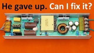
12V Power Supply Repair

Вставка
- Опубліковано 2 лип 2016
- A defective 12V power supply is opened, examined and repaired.
► Support this channel:
Patreon: / jwflame
PayPal Donations: xo4.uk/?PPP
► Social Media:
Twitter: / jwflame
Facebook: / jwflame
Instagram: / jwflame
► Contact info, sending stuff in: etc.:
xo4.uk/?YTT
► Website - More on this video and many other subjects
Website: www.flameport.com
Page for this video: xo4.uk/?PsU - Наука та технологія


Very fine video showing all what is required from carefully opening the small box to examining the internal circutry, finding the faulty component and performing the repair and finishing the repair job.All done with very fine images and good explanatiations during the work.
I don't know much about electronics but as a doctor I've sewn plenty of fingers and thumbs back together. That knife!!! Apart from the scary bit I really enjoyed it. Thanks.
This was so much fun to watch and discover these problems with you. I've had devices that came back to life once the shorts had been resolved just from cleaning the PC board. It also looked like R10 had been rusted at the bottom, but that's great you found it as a cap that was messed up. Great video, 5 years old and one of the best.
Few people have a camera set up to allow the viewer to inspect components visually with the tech.
Thanks for the video John. It just goes to show how a device can be rendered useless by one failed component. We all come across this sort of thing every so often and just pitch the device into the bin without even trying to fix the real problem. This makes me think of all the electrical stuff I've thrown in the garbage when it could have been fixed by replacing a $2 part.
10c part, if that.
It makes me cry any time I go to the local recycling centre and see the kinds of stuff people/businesses throw away. You just know that, with a little technical knowledge, a ton of that stuff could be repaired easily. And guess what; as the tip is controlled by the local council, you're not permitted to take anything from it.
This is the first video as to where I can at least see all of the parts for myself. Thank you for that info as well on what you used. Now if many, many other u-tubers would follow with your example then they would probably grow to millions of fan based customers wanting to learn electronics. Good video all in all as well.
Whenever I troubleshoot power supplies and other electronic equipment I always suspect any electrolytic capacitor that is mounted close to a heat source, such as a heat sink. In this video the capacitor that failed is mounted right next to what looks like a FET or some other transistor mounted on a heat sink. The heat generated by this component dries out the capacitor and hastens it's demise. I see this all the time in power supplies in LCD TVs, computers, etc. Sometimes you can actually see the capacitor bulging on the top or bottom as the heat caused it to swell up and fail. Most of the time you can simply replace the capacitors to fix the problem, however on occasion the defective capacitor(s) will cause other components to fail which can be more difficult to troubleshoot and find replacements for.
Thanks for the tip, very easy to look for before going the long ball for repair.
almost all of my monitors and flat screen TVs died because of bad conaxon caps used in them. I went and ordered the the best caps I could find, repalced them all and am using the monitor right now to tell you this. The monitor has been working for 3 years now
@David Parry yep, the infamous 'capacitor plague'
after suspecting the capacitors, look at the output transformer next. the industry has been using low temperature plastic insulation on the transformer magnet wire so it melts off at 250 degrees to aid in soldering.Over time at 150 degrees the insulation breaks down, that way they sell more products. Gone are the days of high temperature enamel insulaion.
@@rogerd4559 hmm,yeah, i have some enamelled wire with coating that easily melts off when soldering, its about 30 years old, though, got it from RS, also got other stuff with coating much harder to get through and tin!
Lovely Video.
Thanks for all the trouble shooting steps you have taken to arrive at which component was at fault!
Cheers
Those are normally sonically welded (as you discovered). If you *think* that there's a screw lurking under a label, it's better to just give it a couple of pokes with an x-acto, awl or similar to "break thru" the label. This way, if there aren't any screws you haven't destroyed the label for no good reason. I prefer an x-acto for this job because if you do discover a screw hole, it's easy to make a clean round slice around the screw hole for screwdriver access.
Least boring PSR vid I have come across. Subbed. Lack of waffle/flannel hugely appreciated.
I wish you would have shown how to test all the components that you said you tested and they were good. Thanks for the video.
Excellent video close-ups! Best I've seen on UA-cam!
close-up camera view during inspection is extremely helpful
Dear JW, I always enjoy your informative videos.......Please keep up the good work..MUCH better than what is on TV nowadays !!!
hi
at first I cursed the government for stealing public tv from the consumer. but now I realize that I can watch any show on You tube and pause it when I have to do other things, like sleeping eating etc. for thirty years I have missed the ends of counless movies and shows because of that
Nice video. I used to inspect electronic goods manufacturers in China a lot in my old job. Most factories i visited had excellent quality control systems, but some were just terrible. No environmental controls anywhere and really high humidity meant components would sometimes be in a poor state of corrosion even before they were placed on the boards.
It was sitting on the shelf since 2009 and the seller wanted to clear out the old stock before moving the new fresh merchandice. Electrolytic Capacitors are like batteries, they have an electrolite and is usually an acid and when they leak its in the form of a vapor and they corrode many other componants and the lands of the device as well as dry up and become useless. In addition to replacing that cap, Mr Ward should thoroughly scrub that whole board down with alcohol or flux remover to prevent future failure from the electrolite deposits obviously sprayed all over!
Nice - i couldn't help thinking, "hey, this fellow sounds a lot like the voice in my head when i'm muddling through some problem or another (but with an other-side-of-the-pond accent)."
Some of these power supplies/adapters can be so intimidating... it's refreshing to see a unit with a straightforward layout. I'm working on a few Dell PC power supply units with no obvious faults, and this video gave me some inspiration to dig back in. I think it's time to invest in a reliable capacitance tester, since problems so often come down to those failed electrolytic caps.. just haven't seen them vent from below in my limited experience. Good to be aware of - Thanks for sharing!
Forget capacitance tester. Get an ESR meter via eBay. Or one of those fancy "Peake" ESR meters as used in this video. Far more useful for checking electrolytics than measuring capacitance - especially if the capacitor is in circuit.
Cheap ESR and capacitance meters are better than nothing, so long as they aren't fake. Cheap ones are what I've got, and they're good enough for troubleshooting.
I'm not sure about your Dell power supplies, but I've seen PSUs that use their RF shielding or metal case as a substitute for a ground plane. Because it connected the PCB grounds together, a loose screw could prevent the power supply from operating. It's a rare problem and discovering it can be a major headache.
Incredible troubleshooting Techniques to repair switch mode power supply. Thanks for sharing your excellent experience in Electronics
Thanks very much, lovely camera work and great Cricket Commentary!!
Lol😂
Thanks for taking the time to do the video, I learned a little and have a few PS's to play with.
That's just it! He did not take his time. He just rambled.
Well done sir! You inspired me to do better next time I get a phone call like that, recognizing there's another person that needs help on the other end of that call.
Hello John well that was the electrolytic fluid that had leaked out the cap causing issues with the circuit board
Your repair video is worthy of my subscription. Well done.
Hi John, Thanks For the teachings very very helpful am grateful
Hi John!
Just some thoughts from me, I repair consumer and industrial electronics for a living in Germany and as its almost always the PSU that fails I've had a lot of experience with smps's.
First thing I check after the visual inspection is always semiconductors. They like to short out when they get hot.
If they're all OK, I will power it up with an adjsutable isolation transformer and see where voltage is present.
It there is a voltage at the main CAP, I'll go to measure AC voltage at both sides of the transformer. If there is voltage, I check the secondary rectifier/regulator curcuit.
So in this case there probably wouldn't be voltage on the transformer as the control-circuit has a fault.
Which means I'll have to look in the primary control circuit.
As the semiconductors were already checked, there are only resistors and caps left (Inductors rarely go bad, I check them last)
and I can say from experience that most of the time these tiny caps dry out and loose capacitance. The big ones on the other hand like to overcook which can be observed quite easily.
Note on testing components: I check Semiconductors in circuit with my fluke. If I'm not sure I'll desolder it and test it isolated from the circuit. Most of the time there are other components interfering with the measurement.
Which is why I always measure resistors, caps and basically every other component out of circuit. Just to be extra sure and don't get confused.
Side note on the Cap-Tester you use. We've got one of them at work too, unfortunately the old kind where you have to press the test button with your third hand while holding the leads with the other two :D
I've come across a device called M-Tester on ebay, apparently some guys in a forum developed it ages ago on the basis of an arduino.
Then somehow the chinese started making it.
Its like 10 bucks and can test pretty much everything with extraordinary accuracy (for the price).
Resistance from 10mOhms up to several MOhms, Capacitance from pF to milliF (including ESR and Vloss), Inductance, diodes, transistors(amplification and switch-on-voltage), mosfets and more. (Its got three connections it can measure between)
The way I view it is that it takes the component in question and tells you how it would behave in a circuit. Very helpful, I've had caps being measured like resistors and transistors being measured like two diodes.
Funny irrelevant story: Recently I came across a TO-92 resistor in a Denon Amplifier which had actually gone open circuit! No measurable resistance whatsoever between all three legs!
So apparently semiconductors don't always short out but in like 99.99% of all cases. I guess the internal leads overheated and melted away.
Lead-Free is easy to use, just get a higher temperature on the iron and use flux. In trade school we had a SMD soldering challenge and the teacher supplied us with Lead-Free solder. I didn't even notice it, I thought I was soldering with leaded :D
and the caps in the psu failing?
not all lead free solder is high quality like you used in trade school. If you buy the garbage from Ebay you will find that out
Was thinking of that cap or the 2 series resistors that feed it a start up supply. Board is typical of a water wash to remove water soluble flux, done with old water and with almost no final QC aside from a final test after assembly to see it lights a lamp and does not blow up. Otherwise could also have water picked up during storage in the manufacturing plant or during shipping via container to the UK.
Label saying made 2009 is very likely, as it would have been excess stock picked up by the lighting assembler to make up the kits, using whatever was available in the market and which was cheap yet met his requirements as to minimum and maximum voltage ( could have used 11-14V output) and which was at a minimum spec for current.
Just a quick device protection and/or safety tip regarding the uninsulated ends of the PSU output.
I find that when I have the extra wire length to spare, it greatly reduces the chance of a short circuit, even when I attach test clips to the wires, if I first cut one wire so that it is an inch or two shorter than the other wire. That way, even if the wire ends or test clips are set on the test bench and would normally re-align to be adjacent to one another and likely to short out...as seen at about 15.00 in your video...with the physical separation they are now much less likely to make accidental contact.
An alternative method if the wire length and leads permit it, is to fold one wire back over itself and tape it or rubber band it in that position. Again, the point is to make it more difficult for the ends of the wires to contact each other by accident.
good tip
I do that with LIPO batteries when soldering connectors on them. also discharge them to a safe minimal level.
I have been watching your videos for 9 hours now. Not tired yet. I remember last time i did something similar was the time that i was watching season 4 of game of thrones.
I mark each video that i watch with a like.
I'm a mechanical engineer and a boilermaker who is is familiar with hydraulic and pneumatic systems.
Your videos are so useful for me. Thanks again John
Great video as always .Keep the good work sir .You are the best teacher .I have learned a lot from you 😁
calm down, love
I was about to complain about the soldering job. But after you mentioned about it being lead free solder, I will recall that comment.
In fact, I dare say it was a good joint, as far as lead free solder goes.
From what I've seen, it's nasty stuff. I'll never use it.
If they ever consider banning it completely, I'll stock pile a tonne of proper solder and treat it like gold.
I've got a 500g reel of lead-free solder. I can't bear to just throw it out, because it has silver in it. It sours my mood every time I see it!
I still use leaded solder so I always have a good solder joint
I cannot get a good solder joint with lead free solder and I have been soldering for over 50 years
@@rogerd4559 lead free solder, especially the type that DOESNT have silver in it, is rubbish.... tried both with and without...
why are we worried about lead when we are dumping barges full of dead flourescent lamps into the sea and coating the bottom of the oceans with mercury?
Hi John
I saw a video today from 'Mike's Electrical Stuff' and his tip for getting apart boxes like you had here was to hit them hard with a big flattish handled screwdriver along the join many times, this will break the ultrasonic bond and keep the flange so you can re-glue later
yes I have been doing that method for years but what I didnt know is to put them in the freezer first suggested by another viewer. That makes the bond even more brittle and easier to seperate
Ive heard putting in the freezer for half a day then hitting them with a wooden mallate along the seam line opens them quick
and if you crack the case, you can always repair them with fresh cyano glue
You left out one major important detail! that is before you do that put them in the freezer for 24 hours. if you dont the crack may go over the case and not the bond!
The sticky deposit is uncured epoxy resin - from the manufacturing process which sticks the two halves of the case together. Clearly a blob got onto the inside of the case before it was selaed...
these boxes are ultrasonically welded, no glues used. it is potting compound or epoxy that is used in the factory not on this product though. somehow it was there accidentally but the casing was re-used as they see no harm done. but it made the whole world wondering why it was there.
You are Tefal Man.
Hooked on these videos, not getting much done at home.
Really enjoyed watching...and some good tips when soldering great !
Hi John, you put on a better understanding correcting the subject matter thank you
Nice job JW... i
I like that capacitor tester... 😏
The opto-coupler leads were well corroded, unusual...
I think I'd have scrubbed the board where tracks looked dodgey & tinned them to help with current-carrying capacity & "structural integrity"...
SMPS's running at khz tend to draw crud lime a magnet... but this thing was sealed... 😕
You are right, that leadless solder is such crap... 😂
Thanks for the close-up... 😎
trouble with all my capacitor testers not one esr reading agrees with the other one. they need to standardize the calibration
combine that crappy lead free solder with the corrosive flux paste they have on the market and you have a complete disaster
That brown stick you found on the bottom of the dead capacitor was probably the internal liquid they have. Try to open or cut in half a new capacitor and you'll see they're not dry inside, so if you ever find some kind of leak arround a capacitor (or a color change in the board, easier to spot with black light), then that capacitor is either dead or somehow injured... I love to see ppl fixing this kind of stuff, i hate the programmed obsolescence, and how everyone is used to it, never trying to open and fix things, they just throw it away and buy a new one... isn't that ridiculous?
Anyway... good video!
Programmed obsolescence
Planned obsolescence can be a good thing with people throwing out good stuff. It gives the REAL experts an opportunity to find some really valuable items in the trash and fix them
The troubleshooting process is great. I'm much concerned with the testing afterwards. Just plug to mains is not a good practice. Would there be some 'safer' ways to test ?
Another enjoyable clip! Thanks J.W. The sticky stuff??? Although the unit is sealed, a possible reason for the sticky stuff and its location over a heat sink might be to collect any airborne contaminants.
when replacing Electrolytic caps if you want it to last a long time, use a name brand like Sprague or Cornell dubilier. there are many other good brands, its easier to just avoid the brand that failed in whatever it is your fixing
Rubycon and Chemicon caps are really great caps to use as well.
Also spend the extra 5 cents and buy a 105 degree cap.
@@nightshadelenar It doesnt really matter what caps they are now days as they keep them on the shelf for 40 years and they dry out so test them all with an ESR meter. I found half were bad right out of the shipping package
@@rogerd4559 Damn, something to check.
Good repair job with nice camera works
Enjoyed your video 🙂 proves the point not all broken caps 'look' bad. Thanks.
Same goes for people...
I love these things... All "IDENTICALLY DIFFERENT" :) Something new each time. It's amazing how so many devices have bypassed the saftey governing bodies, like U.L. etc. Actually, quite un-nerving. It's good we don't keep these in our houses - Oh Snap! Thank you for the teardown and ride along. You RoCk (even 7 years ago:). p.s. Outstanding camera work! Cheers from So.Ca.USA
Good result. Videos like this one do a lot to reduce the amount of junk going to the local landfill.
Good presentation would be interesting to see how to test all the items onboard particularly the transformer!
they sell tweezer LCR meters reasonably priced I got one from Global specialties at Amazon around 40 dollars
An old ham radio engineer once told me 50 years ago "when repairing/restoring old equipment, just replace all the electolyic capacitors and 99% of the time it will make it work like new. they dry out over time
nope, not always, waxed paper dielectric caps are more a problem, in valve equipment, but yes electrolytics do dry out eventually, depends on hours of use and temperature more than just 'age'
After a shock my psu is defect. What is the problem please?
plus other components can and do fail...
"replace all caps" is NOT a magic cure all or guarantee for no future failure
@@haitemhichri9171 we need more information? what shock? what psu?
@@haitemhichri9171 you zapped all the semiconductor devices
destroyed them with ESD
@7:30 it looks like a capacitor discharge possibly ? Have you ever used uv light to inspect the boards ?
how does the uv light show capacitor discharge? just asking
This is a very interesting video.
Thanks so much for sharing.
In my experience. I always check big filter capacitor 400V for stored dangerous voltage... specially if fuse was not open... This means Power transistor did not oscillate and consume charge current of big capacitor...
It's also good practice that you replaced defective capacitor with higher working voltage. To avoid re occurrence of same damage...
just jam a screwdriver accross the caps leads to discharge it
Thanks for sharing, I learn a lot.
A trick for cleanly opening those: Slice the sides with a knife, then squeeze in a vice along the seam. should pop open.
or forget the knife and stick directly in a vice, making sure the seam is in line with the vice jaws as the vice needs to squeeze the seam to break the seal and pop the brick open.
I've also met with corrosion in a Chinese PSU. Probably tears of children working at the manufacturing line.
I think in this PSU it is the crud from that "no-clean" (but actually does need cleaning) flux.
Magdaléna Jírová if it was made in America that sticky stuff inside might be from some guy jacking off.
Power supplies placed in the voids or attics of houses often get mouse and rat pee on them. Both these rodents pee almost continuously as they wander around the neglected spaces in your house.
If mice or rodents are able to get in the psu they dribble urine all over the componants and corrode and short out everything with their acid urine
its because of shipping in containers over seas .... and because of the salty weather / athmosphere
Excellent video. Thanks very much.
Thanks for the video. Your camera was nice as I could see the parts. Wondering if you could share what you were using as a camera. I was thinking that would be great in working on something to have a setup like that to be able to see small parts on a screen
Panasonic HC-X900 with an additional +4 lens.
John Ward
John Ward
John Ward
thanks! great camera!
Very nice. We have the same Atlas ESR tester here.
Overall it was a good video. Few points addressed by some viewers were very worthwhile too. Personally, I would have liked to see the output of the supply on a scope prior to make the repair. As mentioned by the viewers, testing the replacement capacitor before putting it in place would have been useful too, specially knowing that for SMPS power supplies, capacitor ESR is an important element because you may have sufficient capacitance but if the ESR is too high then the circuit won't perform as expected. Using a sharp blade the way you did was scary, This is NOT an approach I would recommend. The dremel and/or the "gentle" hammer knocking technique has proven to be a much safer method for most of us. Overall the intention was good, but the approach could have been safer.
I was cringing - waiting for the spurting blood. As you say, a miniature circular saw on a "Dremel" motor does the job but I would hold the box in a vice or in a hand wearing a leather "welder's" glove. I've also opened such PSUs with a "Junior" hacksaw.
that is in the next video
I've found the best way to open these ultrasonically welded cases is:
Use a 1" wide putty knife or chisel put in the crack between the two halves. Then whack the back of the putty knife with a pair of pliers or small hammer. It needs to be a fast and light impact to break the joint. You need to work your way around the case, but usually it's a nice clean way to pop these cases open.
@@mikebruestle218
I personally would have used a 6 pound hammer, so the knife was a very wise choice IMHO. Often people use what they are comfortable with, you might not be a skilled as John, but you'll get their in end.
Good video. Thank you. I find it much quicker to just replace the suspect capacitor with a better quality one. No need to check it.
Can be possible the the sound starting cracking -failing every second twwo ,some time if is issue the capacotor ? thanks Andy
Sounded like a Mumble rap video 😆 but it's a really good video
your video is just fantastic!!! Truly indeed great instructional format!!! Sharp focus and no wiggly movements not to mention the magnified view of it!! One thing though, the accent is a bit too English and fast.
What accent would you expect English to be spoken with? Indian? Pakistani? Australian? South African? And as for "too fast" please click the gearwheel icon and select whatever speed you prefer!
Bad capacitors are a common problem on those switching power supply unit !! The peak capacitor tester is a good tool for testing capacitor, I have one, and I use it on a regular basis, great tool, a must have !
Thank you for making and posting this video. Good job on that. God Bless. tonyd\.
Just to clarify it's faster to remove some components in the way he did. It's nice to know he confirmed the capacitor being defective.. Thanks for the video. BY THE WAY I LIKE YOUR ACCENT.CONGRATS.
I have an ancient capacitor testorwith the green eye indicator tube and a big dial when you turn the dial the two green beams come togetherand the dial points to the capacitor value being tested
back then they were more concerned with Power factor and never heard of an ESR value. I wonder if they are the same thing?
Nice repair,correct and direct capacitors are usually the culprits, check always, its and advice, working temp spec, normally these low cost power supplies save costs with Elcos
Thanks for useful information. Would one be able to repair 230 AC to 9 volt DC Roland power supply? The output is to high. It reads over 14 volts out.
The glue was mistakenly poured there, it was to tack the transformer on the other side. The corrosion was due to keeping the item in the basement of a British home for more than a year or so.
There are quite a few electronics repair video makers on You Tube and I find them interesting and informative. I've been an electronics engineer since 1969 but still find myself learning new things from these videos. However, it always amuses me that many of them have a grand array of expensive professional test equipment on show in the background of their "lab" or workshop, - mainly to impress the viewers I think. "Mr Carlson's Lab" for instance, is one such example.
Such ostentatious displays don't necessarily reflect the ability or knowledge of the presenter, just the size of their wallets.
This test gear is then used to diagnose and repair the fault on some cheap Chinese gadget or a crappy old radio which would have cost very little to throw out and replace.
Novice electronic enthusiasts may be daunted to think they need all this stuff to sort a fault that needs only a cheap moving coil multimeter, a kitchen table, a soldering iron, a few tools, and a little knowledge.
I've watched Mr. Carlson''s Lab he's an excellent tech, really takes the time to do a neat job and I'm very much like his channel.
@@cat-lw6kq I agree, he is knowledgeable. I have learned quite a bit about repairing 1940s era radios from watching his videos. Now I am looking for a faulty 1940 radio to practise my newly acquired skills.
thanks your help ,i had the same problem.now its fix because your a very good teacher .thanks again.
Which flux did you use and was it to separate the solder between the two leads of the capacitor?
I do like your videos trying to learn how to solve problems with capacitors on washing machines,dryers well done🤗
I repaired a 12V DC SMPS rated at 4.16A, and designed for a respirator. There were several electrolytic caps with the 105 degree rating, but the main ones which were low were surrounding the 'chopper' IC, (TO-220) mounted on a large heat sink, which had fractured, throwing a piece containing the number of the device manufactured by Fairchild. Some improvements were made since (a slightly different number, but an improved variant), so I fitted the improved version. The components I changed were all of the electrolytic capacitors, the chopper IC (took several weeks to arrive), and a fuse. On completion I used Isopropyl Alcohol and a toothbrush to wash the board from any ionic residue. It was made by 'Respironics', and would have functioned for 10 years. It used several obscure values for the capacitors; 1500uF, 25V, 1200uF,16V and so on. I managed to replace them with 'low ESR' types, even though they cost more.. Didn't get back to service as a respirator supply, but works fine with my car radio as a USB Player/FM Radio/CD Player/Amplifier in my bedroom..!
maybe it will come in handy as a respirator power supply when you reach old age?
@@rogerd4559 I hope so..!
@@rogerd4559 Well, I could re-deploy it to your suggested application, and as batteries are very much on the improve to replace its current use. Haven't got to the stage of needing it, but perhaps you thought I aged writing the detailed comment...!
Good info and Amazing camera work. TU
I believe that the overall corrosion and white mist throughout is from the failed e-cap. If e-caps overheat, they can outgas and cause this condition. I have seen it often. Also often, there is no deformation of the cap, or visible leakage, with this type of failure. It is harder to find, visually, because the mist travels throughout the project box, corrodes everything and makes a big mess. As the mist remains corrosive, it should be cleaned from all surfaces, before calling the project done. Great video, instructions and repair job. Good of you to save a device from the trash.
In my experience, an easy way to open that type of clipped/glued box is just to hit it on the side with a hammer (not too hard) and it should just pop open. It's easier than trying to pry with a screwdriver anyway.
squeezing in a vice works well too.
Putting it next to an open heat source works too.
Alexander Harknes
That's also what I am doing. A sudden knock near a corner with a pliers or hammer will open the box. Sometime i squeeze it using benchvise until it flick.
One more way to get it open, just put some drops of patrol on it after few seconds it would be open without any force
One of the best closed up video of electronics I've seen. However no inside ps ac or dc volts or amps measurements or scope waveforms, thanks anyway ...
Hi John Ward have you every opened up a 0-10v dimmer to see what’s inside and how it is constructed
Great tutorial. Thank you
Job done JW - great stuff!
Great camera work.
That Capacitor spewed it's guts from the bottom around the leads as there was no vent on the top, the electrolyte is what caused the opto isolator leads to corrode. You should replace all those capacitors as they will all fail soon and when those big ones go they will drag other components down with them.
I agree and maybe even the Optoisolator as well
I agree it is foolish economy to save caps just because they tested good. they came from a low life Manufacturer and soon the others will spew their guts as well
hi John ! i like how u fix the power supply! i wonder the atlas ESR+ u use is simple to use for a beginner with no knowledge to do a component test!
Good those Peak testers. I love mine!
You were lucky this time. It might very well have been the switching transistor, fuse, bridge rectifier, driver Ic given up the ghost..This has happened to me very often.
These types of boxes can often be opened with a vice or a few hits from a mallet.
It did look like it has a very low clearance distance between the diode heatsink and the blue safety capacitor.
You have a good eye, I totally missed that. Most likely the end of the heatsink was designed to be wrapped in tape. I have seen that often, and while I think it is a bit of a hack it meets the requirements. The spacing isn't so bad otherwise, so I think the design was safe originally and they just cut corners later. Definitely warrants fixing, this is dangerous.
I looked for it. I review usb power supplies and one of the things I do is disassemble them at look at the safety and you are right, everything else looks decent. Not like the one I have just disassembled: less than 1mm clearance and Y cap is a 1kV cap, not a real Y cap.
What I don't understand is why even populate the Y-cap with a non-safety part, why not just leave it out? I have measured emissions on many power supplies which far exceed the limits, it's not like they care about EMI any more than they care about safety.
use a chain saw its even faster
Good repair. I wish you would have shown how you tested each semiconductor to ensure they were not defective.
Did you notice how the cap didn't have a vent on top, so it leaked out of the terminals. That's probably what that brown stuff was.
yup
most definitely and a sign the manufacturer used bargain-basement components
Thank you - nice video.
Assume you tested the ESR of the new cap before or after installation and just didn't mention it.
Thanks for the video! I only have a regular multimeter, how can test the capacitor on the circuit without the gadget that you used in the video ?
I always clean board with isopropyl alcohol,wet dirt or old glue may conduct.Brakes on the board need solder with naked wires.If you want awoid further problems use good low esr caps and seal ewerything.Thanks for the video.
The board didn't have brakes. There was no way of stopping it!
Would love to see some more repair videos!
ok, after watching another video or two, was clued in, No need to reply back to me, TY. nice informative Videos
is the atlas ESR+ device for checking damage component?
Heat the parts a little longer allow the metal leg to heat slower to melt the solder don't melt it with the iron. dropping cold solder will/could fall off the pad later.
Love the channel you're helping my daughter with her apprenticeship cheers😉
Way to Go! we need more female electronics techs and engineers
At least all the caps are rated at 105 deg C. In this kind of PSU, unless the fuse has blown, the startup cap is the first thing to go for.
Technically they aren't rated at 105 deg C, they have a guaranteed life at 105 deg and it's normally only 1000h. If you need a longer life you have to ensure they don't get as hot. That may be by limiting their ripple current or limiting the max ambient temp or whatever else. Every 11 deg C reduction in temp results in a doubling of cap lifetime. Basically all these cheap Chinese psu's fail because they are really badly designed and underated for their application.
I have a problem, I have bought a "300W XL4016 DC-DC Max 9A Step Down Buck Converter 5-40V To 1.2-35V Adjustable Power Supply Module" & some 5K Potentiometer With 10 Turns to build a variable power supply a few days ago. But now I have noticed both the Potentiometers used in the buck converter are 10K. I will replace them with my 10 Turns Potentiometers. So if I use a 5K Potentiometer replacing a 10K Potentiometer, will there be a limitation in minimum or maximum output voltage (& current) or that will increase or decrease the sensitivity of the turns? Sorry to disturb you by the way...
"Good", very well done 😎
Tank you John, very interesting
well done , nice video, thank you.
Nice video! In the other side of that charger was six legs integrated PWM regulator ic - I suppose. I have found that kind of IC faulty on 24 V power supply. It's labelled 10 A 38. Where I can find those ic's???
Hi John. Just my thought on the sticky deposit there, given that the case was probably "plastic welded" using an induction coil to melt the plastic together, this would have meant that no glue was used to stick the two halves together. this is quite a common method for sealing psu's together these days. Could the sticky deposit be melted varnish which had dripped from the inductor which may have become very hot during operation, which subsequently settled onto the plastic case? Once cooled it would have left a deposit similar to what you found? Just a thought ;)
These power supplies are specified to last until any warrantee runs out.
They are made in sweat shops in China, Malaysia, or the Philippines.
Until western economies take charge of their own production the garbage pile will grow exponentially.
Thank you JW for an instructive video of how to minimise that garbage pile.
Can repaired items like this be re-installed after repair?