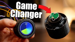
AS5600 magnetic position encoder - best encoder for stepper motors

Вставка
- Опубліковано 18 січ 2025
- In this video I show you how to use the AS5600 magnetic position encoder. This is a very powerful chip for projects where you need a precise information about the position of a shaft. Therefore, it is extremely useful for stepper motor-related projects because you can use the sensor to directly measure the displacement of the shaft of the stepper motor. Its angular resolution is 0.08789°/bit, so if you use it with a stepper motor that has a 1.8° angular resolution, you can use the motor up to 3200 step/turn microstepping and still get decent numbers.
Please don't forget to subscribe if you like the content!
Join my channel membership: / @curiousscientist
Schematics and Arduino source code: curiousscienti...
AS5600 datasheet: ams.com/docume...
If you want to support my work, please consider buying the parts using my affiliate links:
curiousscienti...


i have been banging my head against a wall for days and making no progress trying to figure this out through the GitHub for the AS5600 library as well as the Datasheet, but holy shit, this might be the most straightforward and easy to understand tutorial I've ever seen for anything. You are a god and the comments on your code are a thing of beauty.
I have literally never used an Arduino for anything more then turning on an LED before, let alone I2C protocol but I still understood this perfectly. it is messed up that you don't have more subscribers.
Thank you! I am glad to hear that my code with the comments helped you to understand everything. Unfortunately, it is hard to convince people to subscribe, so growth comes slowly. No worries!
Great video. Despite having worked in electronics and IT most of my life, I still learnt a lot from this presentation. Plenty of detail unlike some examples where buzz words and part numbers are thown out willy-nilly.
Thank you very much! I try my best to provide a detailed and thorough explanation of the gadgets I present so others can learn and benefit from it. I am glad to hear that you learned from my video!
Excellent showing. There are a plethora of encoders out there, linear, rotary, absolute, incremental, optic, capacitive, inductive, magnetic, etc. so certainly is a good thing when someone can teach us and even cover the software. Also, this modules are pretty cheap to be easily adopted.
Thank you! Yes, there are millions of encoders and each of them have their specific application areas. But I am extremely happy about this specific one because I can improve my stepper motor-related projects by a lot!
Great use of this idea in one of my projects. And the explanation of code is out of the world. Best explanation. 48 mins just went like that. Keep coming with more innovative ideas. Thanks!
Thanks! It is nice to hear that you liked the way I explained the code. Cheers!
Some people think that long videos are unwatchable, but if you are a frustrated novice… it’s SO GOOD
@@flyingmonkey3822 Thank you! It is hard to properly explain these topics in 10 minutes, so instead, I make longer "lecture-like" (45-ish minutes) videos. This way I can cover most of the things and properly explain how I wrote the source code for certain hardware. Also, as UA-cam is not my main source of income, but my hobby, I can afford not to try to please the algorithm and make shorter videos for more engagement. I just do it for my own entertainment and for (hopefully) helping others.
Very good video.
AS5600 is a fantastic part. I have used this magnetic encoder for one of my project, and made high precision "potentiometers" with the size of the small rotary encoder 11x11x8mm high and absolutely crazy precision.
Thank you! Yes, this encoder is fantastic! And as you highlighted, it can be used for other things too, not only on motor shafts. A high-precision rotary encoder is also an excellent device to build using this encoder.
You were right, I had printed the code I had the first time and compared it to the original one you have and it was different. I apologize for my oversight. I recopied the code and it compiled perfectly. Thank you.
No worries, I am glad you solved the issue! :)
Дождался, лучшее видео-инструкция по этому модулю, огромное спасибо за труд и код. Проверил, всё работает.
I waited, the best video instruction for this module, many thanks for the work and code. I checked that everything works.
Thank you! I am glad that I could help.
This video is awesome! Excellent explanation, great code and fully understandable to someone who's a amateur Arduino user.
I have a misalignment issue with my two X axis stepper motors on my DIY CNC router and this will be a perfect way to check their absolute position before and during milling.
Thank you for sharing your knowledge. I rarely comment, but this deserves praise!
P.S. Subscribed!
Thank you very much for the positive feedback! I am really happy to hear that you like my content!
nothing really new but I liked the way you explained all, you gave me more confidence with this sensor.. thanks
Hi! It's great to hear that my video gave you more confidence with this sensor! It is a great little device.
You don't know how long I've been looking for a tutorial such as this one. Thank you for your great tutorial
Glad to help!
Take care that you solder the DIR pin to either ground or VCC. He did not do it in this video, and it wont work correctly without this. It will randomly change direction, and this will screw up your rotation calculations eventually. This is really important, and a way to create really hard to diagnose random issues if you dont do it.
Yes, this is a good remark! I actually made awareness about this issue in my other AS5600 video where I introduced my own "NEMA17-compatible" AS5600 board. There I emphasize that the DIR should be tied to GND when it is not used.
I look forward to seeing more videos of you implementing the AS5600 magnetic position encoder in your projects, especially if you are a CNC milling machine.
Thanks! There will be more!
Hello. Getting ready to learn about the AS5600 in conjunction with a 28BYJ-48 stepper, both of which I have already purchased. I found your video(s) extremely well presented and informative and consequently you have a new subscriber! 😀
I have the exact same AS5600 pcb as you and have scoured the ‘net high & low but cannot find a schematic for THAT exact pcb (which seems to be one of the most common ones using the AS5600 chip).
I’ve seen in other places on the ‘net other folks suggesting to make various mods (mostly removing components) for one reason or another but none have actually supplied a detailed schematic of that pcb.
What lead me to REALLY wanting that schematic was I saw in the Mfg.’s data sheet for the AS5600 chip (page 5, Fig. 13) that for 3.3 Volt Operation pins 1 & 2 (VDD5V & VDD3V3) get jumpered together and a (decoupling?) capacitor’s value is changed from 1µF to 10µF. For 5 Volt Operation, there is no jumper and the capacitor is left at 1µF. There are a couple of asterisked notes regarding the 3.3 Volt Operation and “OTP programming” (which I’ll be honest, I don’t know anything about).
I checked my AS5600 pcb's and there is a 0Ω resistor (jumper) installed between pins 1 & 2, however there are no visible markings on either C1 or C2 on any of the three AS5600 pcb’s that I bought, thus one of the reasons I’d like to see a schematic.
I see you’re powering your AS5600 pcb’s with 5 volts and clearly nothing’s exploding. Can you offer a simple explanation what this is all about?
Any chance you might have, or know (link please) where I might find, a schematic for that specific pcb?
Thanks, Rick
I haven't reverse engineered this specific PCB, but its schematic seems to follow the schematic in the datasheet. Just a few capacitors and pull-up resistors for the i2c bus. You can just grab a multimeter and reverse engineer the schematics yourself. It is just 7 components.
I even made my own NEMA17-compatible PCB based on this chip: ua-cam.com/video/RIsUvHZVjuU/v-deo.html
If you don't want to burn in a new zero position, then just neglect the asterisk footnotes.
The chip is 5V compatible, so it is not an issue to use 5 V.
Thanks for the very clear video! Using coaxial cable for the DATA en CLOCK (I2C) works much better than regular jumper/hookup cable. If you have a lot of jitters, missing characters and unreliable measurements please give it a try. Just some cheap (thin) TV coax will do the work. Ground the shield wires to a metal part of your project. With this setup I have a reliable reading with a margin of 0.10 degrees with a minimal delay.
Hi! Thank you for the nice comment and the useful ideas! Yes, a good pair of cables is absolutely necessary for good signal integrity, especially if you want to carry the signal across a larger distance. And not only the cables, but the connections should also be of a good quality. Wiggly terminals and loose wires can cause a lot of mess. For important projects I nearly always solder the cables and I use good quality cables. But for these demos it would be very expensive to always use professional wires.
@@CuriousScientist No complaints from me my man, just a tip for starters. I wasted a day with trying to make the encoder reliable. 10 Meter coax cable 4 Euro. The thick and rigid cables are a pain in the ass in cable management but are essential for reliability. I have no coding qualities but found out that sending raw angle values (1-4096) is more reliable than sending degrees values with a rounding. No jitters at high speed with minimal delay, 5 ms. No complaints, just some findings. Thanx again.
Very nice to see this.
BTW, there is a video on a similar type of encoder on Hackaday. Some of the people commenting there mentioned that the commercial versions are quite expensive.
Thank you! I haven't seen that video and page, but I will check it. I bought these small PCBs for about 2 USD/piece, so it was relatively cheap. In fact, I also designed a PCB myself for this AS5600 encoder chip to fit the back of these stepper motors. But that's for an upcoming video once I receive my packages which are currently stuck at the customs as usual...
@@CuriousScientist BTW, I put a link to your video there
@@7alfatech860 Wow, thank you! Thanks for promoting my work, I really appreciate it! I will upload two other, "more advanced" videos on this topic during the next week. They will be hopefully interesting!
Great video, this detail is amazing! 😃
Thanks!
Really good video. Thanks for your good explanation, it helped me a lot!
Thanks! I am glad it helped!
Awesome, thanks for your comprehensive explanation.
You are welcome! I hope it helped.
Really top vidéo and explanation!
Many thanks...please just continue!
Thank you! I will keep making these videos. These comments are especially encouraging to continue making videos!
Great video!The shaft is Stainless Steel, that is why it's non-magnetic.Some types of SS are,but I guess this one isn't.
Thanks! If it is stainless and non-magnetic, it is an austenitic stainless steel. If it is stainless and magnetic, it is either ferritic or martensitic stainless. It is probably a 301 or 304, or something similarly cheap. I was just a bit unsure of the origin of the shaft.
That's true. I didn't know the shaft of my nema17 is SS. Therefore, the magnet could not be sticked to the center. I bought 7 AS5600 though... i cannot use them
Why not put a drop of super glue on the magnet and attach it to the shaft carefully? There won't be any forces acting on the magnet anyway, so the glue would hold it in place perfectly.
@@CuriousScientist Thank you for your quick response. I will try to attach it with bond or super glue. Your advice helped me a lot
You're welcome! Glad that I could help.
Dear, It is a wery good explanation. Thank you for a sharing.
Today I assembled everithing with Arduino Uno and I connected the Oled SDA-SDA, SCL-SCL and working well.
Nice to hear that you got it working. Enjoy!
I want to use this to check my cnc X Y Z axis positions . For that I need your support. . Because I use timing belt whell with different diameter, one turn is not 360 degree . How can I compare it?
I don't understand. A turn is always 360. Otherwise, it is elementary school mathematics.
Dear , yes I know. Sorry for that, I am absolutely beginner. I tray to write it in other way. My machine haw hand wheels and one turn is 2mm liner moving. If I use the moving with stepper motor than one turn is not 2mm because of different timingwheel diameter . My question is how can I reach that the display show the real distance.
No worries. But this is really just basic math, it has nothing to do with coding.
If one turn is 2 mm, then you also know that 360° is 2 mm. The stepper motor at full step microstepping setting usually does 200 steps/turn. Which is also 360°. So now you know that 360° = 2 mm and 360° = 200 steps. So 200 steps = 2 mm. Then 1 step = 2 mm / 200 steps = 0.01 mm /step. So with each step, you have 10 um linear displacement, assuming there's no backlash or other mechanical issues.
Perfect! Thank you!
You're welcome!
This video is awesome! Excellent explanation
Thank you! I'm glad to hear that you like the explanation.
This time we need a closed circuit stepper motor board for Nema 23 and Nema 34. But it is affordable. When you try to buy the boards in the market, it exceeds the price of ready closed loop step motors.
This board is about $2 if I remember correctly. It should be much cheaper than the off the shelf closed loop systems.
Hello, great video and I appreciate all of the details and your code explanation. Just one question, did you pre program the AS5600 with updated values from the defaults? Thanks again and keep up the great work.
Hi! Thanks! No, I haven't touched the AS5600. I get the raw data from it as-is and then do the calculations on the microcontroller.
good tutorial but is it possible to get initial angle of the motor on startup..?
Thanks! Sure, just read the encoder.
very helpful, amazing video
Thanks, I am glad it helped!
It would be also interesting to see how one can read the angular position based on pwm and analog signals with this sensor)
Will do it because I am actually working on my own AS5600 Arduino library.
We can control and maintain the position of stepper motor using and encoder thank you I am subscriber to your channel
Thanks for subscribing.
just a heads up, but you can further reduce that to 3 pins, as the circuit / chip also supports analog output using VCC, GND, and OUT.
While tinkering with them on a benchtop, 4 pins is fine, but when you're talking about implimenting these in real world environments, the reduction of even a single pin can be a huge savings in time, cost, and space.
For instance, in my situation, i'll be using these on a CNC machine for DRO positioning, and when you're talking 5 axis * 4 pins, those drag chains are going to pack up pretty fast.
On the other hand, you need a better than 12-bit ADC to confidently resolve the voltage steps. And it also needs to be fast. And while you might save one wire, the signal between the sensor and the MCU is now analog. It is probably more susceptible to noise. Still, it might have its advantages. Otherwise, the manufacturer would not have put it on the chip.
@@CuriousScientistsignal noise is easily enough to deal with, and cheaply implemented. In my case, i just used shielded cabling. I did end up going with the i2c interface however. (and yes, weather you're using the PWM or i2c, around motors, and drivers, you really want to limit EMI and crosstalk, so shield cable is always the preferred method)
I did have to add an I2C multiplexer to the stackup though, as all of the modules i purchased used the same exact I2C bus address, so in order to utelize multiple, the multiplexer was required. I ended up going with a TCA9548A based solution.
Excellent explanation.
Thanks!
Excellent tuto. tout est très clair et tout fonctionnent
Merci
Thank you!
Absolutely 💯 Amazing 👏 like being I college 😊, thank you for such a brilliant tutorial ❤
Thanks! Glad to hear that you liked it.
Thankyou so much it really helped me a lot
Also subscribed to your patreon
I am making a diy gimbal using stepper motors
So on start is it possible to get initial angle from sensor with a reference so that my gimbal can calibrate by getting data from mpu6050
Hi! It is an absolute encoder, so every time you start it, it will give you its absolute position on the 0-360° scale.
Such a great video. Thank you
Glad you enjoyed it!
Did you have to drill out the end cap to expose the shaft and accommodate the magnet
No! All stepper motors I have met so far had their shafts exposed. In the worst case, there was a sticker over them, but that is easy to remove.
Indeed, I found my Nema 17 had an exposed end shaft - surprising really - you'd think that industry would want this sealed to keep contaminants out - like cutting oil, water or machining powder, but there's no gasket on the and end plate anyway. Just a point to consider
These stepper motors are not made for harsh environments, so I guess that's why it is left exposed.
What screws did you use to secure the 3d printed part to the Nema17 and the AS5600 to the part as well
Some long M3 screws. I don't remember the exact length.
great video thank you for sharing
Thank you! I hope you found it useful!
@@CuriousScientist sure it is
I am wondering how this compares in high acceleration applications vs the MKS Servo42/Servo57 lineup?
I guess, if you put it together with a fast microcontroller and a good driver, it can work well. I haven't tested its absolute ratings, but I might do it in the future.
@@CuriousScientist Cool. :)
Excellent explanation!! But I still don't understand how to use it with two sensors. I'm pretty new and I don't understand where the pin definition is! How to define them? Don't have a simpler library for newcomers?
Thanks! If you need to use multiple AS5600 sensors, you have to use an i2c multiplexer because these sensors don't have dynamic i2c addresses. I have another video on my channel where I built a milling table and I used two of this sensor. ua-cam.com/video/IZ0FyiMYT48/v-deo.html
Otherwise, you can for example use a ADS1115, 16-bit ADC and read the output of the different sensors and convert the analog voltage into degrees.
Regarding the simplicity, I think you won't find any simpler way of doing it.
@@CuriousScientist Thanks for the answer! I'll run some tests here! If I can't use them, I'll try with the CJMCU-103.
Awesome video, Please do a Closed-loop FOC control of Stepper motors, I've been trying to learn some code to do that, but will take time. Thank you.
Thanks! Sorry, but I do not make videos on request. I have a lot of projects lined up and I am working on them.
@@CuriousScientist understandable, please consider it as a suggestion. Thank you for the videos. 😀
Really nice video and very well explained. Looking forward to see more of your videos. One question, can we used the encoder and stepper as a servo - rotate stepper to x degrees with x speed using arduino IDE coding only?
Thank you! Yes, a closed loop control is possible. I will actually work on it and when it's done, I will publish a video about it with all the resources. I need a few parts to arrive and some free time to work on it.
Awesome. That would be great. Thank you
Hello friend, I think you make a good job, I have a question
could this sensor be used to obtain the value in centimeters or millimeters in some way? best regards.
Hi and thanks! Of course it can be used like that if you know the mechanism attached to the shaft. What you are asking for is not specific for the sensor. It depends on how you convert the readings. It is up to you how you design the mechanism.
Excellent video!
Thank you Stefan!
It posible to use magnet diameter 10mm??
Anything is possible. The question is, will it work? Please read the datasheet for the answer. I have never tried it with magnets larger than 6 mm diameter.
The reason why the magnet didn’t stick to the shaft is because the shaft is made from stainless steel which is non ferrous.
A stainless steel could be ferromagnetic, so your statement is not exactly accurate. 😎 If it is stainless and paramagnetic, then it is austenitic steel.
Hi there. Thank you for this helpful video! I need to use it underwater as the rotating object is submerged. I've seen some people use nail polish to make it waterproof. I would really appreciate your advice on best practice.
Hi! I am glad that you found it useful! I am not really well-informed in this topic but as far as I know, you can get acrylic or epoxy-based coatings (sometimes in a spray form) that you can use to waterproof the PCB. Just make sure that you already have the cables properly connected. But once again, I might not be the best person to ask for waterproofing the PCB as I do not have too much experience with it.
Hi Armin! I wouldn't rely on just a lacquer for submerged electronics. Your best bet would be to pot the entire board into some resin or silicone. Just avoid using acetic silicone (the most common sealant in construction) - the one that smells when curing, because it will ruin your PCB while curing. Non-acetic silicone works great, GE Sealant 2 or similar (I have no affiliation with them)
Thank you!
Great explanation
Thank you!
I ordered the 2 of the 14bit versions today. I am planning to pair it with a Rpi Pico to use as encoders for my dobsonian telescope. In this application, I only need to the angle, no need to count number of turns. This should help in finding targets in the sky based on their altitude and azimuth angles.
I don't remember AS5600 having multiple versions. AFAIK it only exists in 12-bit version. So, the "14-bit version" must be something else then. And yes, if you navigate within a full circle (0-360°), you won't need to count the number of turns.
Awesome. THank you.
I hope you found it useful! Cheers!
While listening to you explain how to get a number in degrees, it occurred to me that it may be easier to work in radians. Divide the number by 2048 and multiply by π to get radians. From there, you can convert to degrees if you must. Fiddling around with the 12 bits you're given and turning them into a 4 byte floating point number would be fairly trivial. The float will always be a positive number less than 2, and 2π radians is 360°.
Hey, that's an excellent idea, thank you! Since I want to make a follow up video for this hardware (but based on my own PCB), I will implement the radian-based approach. It sounds smart!
Thank you for the great detailed explination! I am not very good at coding I am still a beginner, Your code is doing al awesome stuff, but I only need the encoder for one spicific thing, if I asked you to simplify the code to few important lines, would you be able to do that? just the bare minimum that reads the raw angle? Thanks!
Hi! You just use the code as is and you get the raw angle. I thoroughly explained the whole code, so it shouldn't be too difficult to see how the output is created.
Is it increment or absolute encoder? If i reset the arduino, will it hold last position?
Absolute.
Very good job !!
Thank you!
Have you made some investigations about temperature drift? How exact are the absolute values if you don't move the magnet over time?
I haven't, but since it is an absolute encoder, it should not be an issue. Check the datasheet, they should mention about it if it is a known issue.
You need to solder the DIR pin to either ground or VCC, otherwise you will get random occasional flip flops of the direction.
This is really important!
Also, if your module has 3.3v and 5v inputs. And you use 3.3v you need to solder the 3.3v to 5v. On this square white module its done by default. But the modules that have both inputs, needs this. Or you will get random issues in connection.
Good remark about the DIR pin! I have another video where I show my own AS5600 board and there I discuss it, but here, I skipped it.
@@CuriousScientist Yeah, just spend few days wondering about the weird occasional errors i got. Have been using these on other projects tracking knobs etc, and never came across this issue. But when tracking fast moving motors, it really starts affecting. Really happy i learned this, as the errors would have eventually came up even in slower moving projects. I disregarded the DIR pins as relating to the analog output.
It seems to be really capable sensor, im tracking up to 25rps with absolutely no issues. It should easily do twice that.
Yes, this is a fantastic sensor and with an i2c multiplexer, you can use multiple of them with a single microcontroller. They are also dirt cheap and have broad area of application if you can write the code for it. I really like this chip.
@@Nobody-Nowhere No offense but I am very surprised you did not handle the dir pin appropriately from the very start. The data sheet is very clear on this requirement.
How did you fix the output jump gap of +-3° at once when close to 0 or 360°?
this sensor gives an amazingly accurate output, but then it fucks it all up when about to make a full turn, it suddenly jumps 2 to 5° rendering it completely useless for use with the full range of the sensor.
Hi! I haven't noticed such behavior. However, you might want to connect the DIR pin to the ground. Otherwise, you may notice disturbance in the signal.
Do you know if this would work to get the position of a linear actuator, if the encoder is measuring the output shaft of the linear actuator's DC motor? I'm trying right now on a linear actuator and it's pretty inaccurate. The same physical position on the actuator will show different positions from the encoder, and I can't figure out why. I thought maybe the shaft was just spinning too fast but it doesn't seem to skip turns except when it reaches the endpoints (I can see the quadrants going 4,3,2,1 or 1,2,3,4). I also connected DIR to gnd but that didn't change anything.
Hi,
I used it both on DC motors and stepper motors and it was very accurate in both cases. Without knowing where and how you mount the magnet and the encoder, it is hard to say anything.
@@CuriousScientist I ended up figuring it out, when I added a delay(2) to the loop it became much more accurate. I don’t really understand why though. Any thoughts?
I don't know how your whole code looks like so it's hard to tell.
@@CuriousScientist I noticed in your loop code there’s a commented out delay(100) where you say the delay can be adjusted for better resolution. Can you explain why adding a delay would improve resolution?
I said "better resolution", in quotes. It can happen that the sensor hasn't settled before performing another reading, which could lead to incorrect readings. I noticed that adding a little delay could improve the stability of the readings, so I just added it there. But ultimately, it is up to the user.
Nice video! I was wondering if i could do tha same with just a hall effect sensor attached to the arduino to read the position of the shaft
Thanks! With one single Hall sensor, you won't be able to detect anything movement related (other than the presence or distance of the magnet). In fact, this chip has four Hall sensors inside and they are positioned carefully so they can pick up the change in the magnetic field. Then their signal is converted into the position information that we read out with a microcontroller.
@@CuriousScientist oh right! So if i attach 2 sensors parallel to each other would it work?
Could work, but not as good as this chip. This chip is so stupidly cheap, it doesn't worth to make any contraptions to mimic it. I am pretty sure you would lose resolution and precision with a DIY method.
@@CuriousScientist hmm but its just that its not available here, and if i buy from somewhere else its gonna take weeks, so time really is the problem here.
I see. I always buy these from AliExpress, I also provided the link for the store I used on my website. It typically arrives in 10-15 days. Of course if you need it urgently it is difficult. It might worth to look around on eBay or Amazon or on your country's own trading website. It is typical that there are people who are importing these things and reselling them on the local trading platforms.
amazing video! I have just one question. Do you know any other such encoders offering at least 0.01° / bit resolution? I need need that for 256 steps microstepping. I tried searchnig but to no avail. Thanks!
Thanks! I have another video on the AS5048A which has a higher resolution, but I think it is still too low for your application. Why do you want to be able to resolve so tiny angular displacement? You could try putting a gearbox between the shaft and the encoder to "magnify" the displacement caused by a step and then calculate backwards using the gear ratio of the gearbox. But I can imagine that the gearbox would not be able to cope with such tiny movements.
@@CuriousScientist I want a resolution of 0.01° for a preicise laser based positioning system I am designing for my bachelor thesis. My idea was to use microstepping with feedback to improve accuracy and count the missed steps.
Now I am in front of the computer (I wrote the precious answer from my phone) and 1 minute Googling gave me a positive result. I don't know how you searched, but you should do it better next time.
Try the AEAT-6600-T16 chip. You can have 0.00549° resolution.
@@CuriousScientist Thanks a lot! Can you share what you searched about. I was probably looking in the wrong place 😅
I actually just used my brain...
You said, you need 0.01° resolution. The encoder presented here is 12-bit: 360°/(2^12) = 0.08789°. Too large. Next sensor I mentioned the AS5048A is 14-bit: 360°/(2^14) = 0.02197°. Getting there... So the next step is 16-bit: 360°(2^16) = 0.00549°. This is good enough. Then I just Googled "16 bit magnetic encoder". I hope you won't take it wrong, but if you are working on your bachelor thesis, you should be much better at searching for information.
Hi i got the same module but analog and PWM output doesn't work and there is no explanation in internet about this trouble : when i use analog output i got in serial 1023 constantly. What do you think about ?
Check the datasheet of the device! The best resource for the device is always its datasheet.
Is as5600 compatible with esp32?
It's not a question of microcontroller. It's a question of whether the given microcontroller has an i2c peripheral. So, yes, it is.
Hello. Thanks for your videos.
I think this board is powered by 3.3V, why do you use 5v?
Thanks again.
Hi! You can use both voltages. Read the datasheet...
@@CuriousScientist Hello, thanks for your answer, I have read the datasheet and I have seen that it says that the two voltages can be used, but with different configuration, this board is configured for 3.3v, since the 5v and 3.3v inputs are linked
I want to connect to multiple as5600 modules at the same time. How to change i2c address for each as5600 module
Hi! You cannot change its i2c address. But you can use an i2c multiplexer. I have video examples on the exact same issue. Search for "i2c multiplexer" on my channel.
This one is one of those: ua-cam.com/video/IZ0FyiMYT48/v-deo.html
@@CuriousScientist thanks
After uploading the program to the board, the oled display is not turning on. When i upload some other oled display code, the display is working and also the display is not working the magnetic encoder. Any suggestions?
Hi! Check the address of the display. Maybe it's different from the one I used.
@@CuriousScientist Dear , I faced with same issue.The solution was for me that I start turn the magnet and the welcome appeared on the screen.
Yes, that could solve the issue because sometimes the encoder doesn't detect the magnet when it is not moving. And the code is written in a way that it does not proceed if the magnet is not found.
So when you spin the magnet, there's enough change in the magnetic field that the encoder can detect it.
However, this means that you need to move your magnet closer to the encoder.
Hi sir great video it's really helpful,quick question my sensor keeps jumping in it's readings no matter how i place it (even though i made a 3d printed casing for it and placed it behing the motor)do have any idea how could i fix this problem ? the gap between the sensor and the magnet is aprrox 0.5~1mm
Hi and thanks! Based on the gap you said, the distance should not be a problem. Is the reading random or just jumping between two adjacent values?
if u could send ur email ill send u images of the readings thx in advance
It's on my website, but keep in mind that I am not a free support service.
There is a setting to control the hysteresis value, if that helps you but there are other factors contributing to this problem show as below.
Don't forget to connect GND or VCC to the DIR pin. On some boards, this issue occurs as the pin is kept at floating state.
Other reason is bad wires picking noise.
Readings jumping with a value of 0.05 plus or minus is normal.
@@bhupiistersingh4097 This is a good remark. Actually, on this board, the DIR pin is supposed to be tied to GND if I remember correctly. But otherwise, yes, it is very important to not leave it floating. I made my own custom board with this AS5600 chip and there I highlighted this issue and recommended tying the DIR pin to GND, otherwise, the values will be fluctuating. In this video, I got the values really stable.
Is this PID or LQR closed loop on 1/16th microsteps?
That would be really useful, because the torque variation between microsteps prevents 1/16th accuracy even with just the tiny bearing friction. Sometimes shaft doesn't even move at all!
There's no PID in this demo. However, I recently uploaded a PID-based stepper motor controller using this encoder. Check my newest videos.
Does the motor itself affect the position accuracy? I read in the datasheet of an encoder that magnet should be mounted on a non-magnetic thing and surrounding magnetic things can affect accuracy
Hi! As far as I experienced, no, the motor does not interfere with the accuracy. At least the NEMA17 stepper motors are working well with this sensor.
@@CuriousScientist | Thanks
Sir could you please explain about raw angel how to calculate raw angel and also explain raw angel calculation done for motor or sensor
Yeah, it is in the video. Watch it!
Hi sir, from this tutorial is posible to move stepper to the own angle? Like a servo ( servo.write(90) ; and the servo go to 90deg) it posible to like that? Please answer
Hi. Yes it is possible. You know the resolution of your stepper which is typically 1.8°/full step, so you can convert the steps to degrees.
@@CuriousScientist yes my stepper 1.8deg (200step) so wich code to move stepper to the angle? I use as5600 also, if you can can u make a video
Follow my videos and read what I published and you can figure it out.
@@CuriousScientist yes i still learn from this video but iam new programing sir
can we use it to find rpm ? of stepper motor? if not could you please suggest any incremental alternatives
Yes we can.
@@CuriousScientist could you please share any article video or resource on how?
It is in this video... Check the angular displacement every two seconds and extrapolate it to one minute. Divide the extrapolated value with 360°. It is not difficult.
What is the name of a proper magnet of this kind ? (Thank you)
I think I mentioned in the video, and I even provided a direct link for it on my website under the parts and tools page. It can't be more obvious........ It is called diametrically magnetized magnet. You can also read the datasheet and see what magnet is needed.
@@CuriousScientist thank you
Hello, could you throw off a 3D model for attaching the encoder to the stepper motor? Thank you for such an informative video!
Hi! I uploaded it, you can find it on my website (see description). The reason why I haven't uploaded it from the beginning is that I am not 100% satisfied with the precision of the model. It is a lazy design. It works, but it could be improved. I hope you appreciate it.
@@CuriousScientist Thank you very much. I will wait for more videos about this encoder. It would be nice to see the implementation closed loop for control of stepper motor. So that the motor turns at a certain angle and holds the position.
Building a closed loop control based on this AS5600 encoder is actually on my to-do list, but it will take some time as I want to implement a complete library. Something like the accelstepper library, but the library would rely on the angle of the shaft instead of the steps. But because of this, everything has to be reimplemented: speed, acceleration....etc.
@@CuriousScientist That sounds cool! I will wait))
Great video!
Glad you enjoyed it, thanks!
Just joined your patreon website...I sent a mssg on your Patreon group inquiring about your PCB for NEMA 17.
Hi and thanks for your support! I saw you message and replied. Cheers!
Very nice thanks!
I tried this code and the Seeed-Studio lib... but i always see the same noises!
There are randomly spikes in the angle signal (i2c connection, about +/-20 degree spikes).
I already changed AS5600 boards and magnets... but always same.
Does anyone have the same issue or know the cause?
You're welcome! I saw that other people are also having some issues with noise or random fluctuations. I will revisit this device again soon and see if there is anything that I can do. So far, I haven't experienced any issues with it. How long is the cable that you use between the microcontroller and the AS5600?
@@CuriousScientist
Thanks for your fast reply!
Im using two of them... one is about 20cm, the other is about 30cm.
I just get spikes if i rotate the magnet, if it stands the signal is fine.
Hi! Another very helpful viewer recently commented that the DIR pin has to be connected to ground. This solved his issues. Could you try the same and see if it works for you?
@@CuriousScientist I tried now... but unfortunately its still same.
I solved it with a software filter atm coz its always the same spikes... not ideal but works for the moment.
I will keep working on this, but please allow me some time because I have some very interesting projects lined up that I want to publish first. But I will not forget about this as this can affect other people who use my code as well.
The magnet encoder as5600 that I bought is missing,
can it be replaced with a magnet neodymium?
It is clearly stated in the video and in the datasheet. If it is diametrically magnetised, you can use any magnet. The gap might be adjusted due to the different strengths. But I recommend ordering a proper magnet, they're dirt cheap.
Do you have any suggestions for overcoming this sensor's 10-lsb hysteresis? For me it is resulting in a deadband of roughly 5 degrees for 355 - 0 degree turns.
Hmm, I have never heard about or experienced this thing. Could you tell me how to reproduce this thing? Then I will try to think about some solutions or workarounds.
Is it possible to use a ordinary magnet with poles on each end but place it horizontally to the AS5600 and achieve the same results?
I don't think so. The magnetic field lines have to go through the sensor perpendicular. If you rotate an ordinary magnet, the lines become parallel.
@@CuriousScientist Thanks for the explanation.
You are welcome! There should be a link for the diametrically magnetized magnets in the description of the video. They are not so expensive, it is worth to stock up from them.
@@CuriousScientist Yes I saw the link, Thank You.
I live on a yacht. I want to make a wind direction sensor. Longevity is an issue in past experiments. Wire wound resistor wear out. Timing a magnet that spins has its own issues. I am thinking of using this technology to get wind direction, by mounting the magnet on a wind vane. I will just transmit this data to my receiver unit/display. I hope the units i am buying of Aliexpress are not some cheap magnets that lose magnetism after 4 weeks.
This should be hassle-free. Magnets losing their magnetism sounds weird. By any chance, did you heat the magnets up to 3-400°C? Or, were they exposed to any other magnetic fields? These Nd-magnets should sustain their magnetization for quite a long time. But yeah, as you mentioned, if they are some cheap garbage, they might not perform very well.
@@CuriousScientist I wrote the message on a phone. The magnets didn't lose power, i was wondering if the Chinese ones did. I did try to get the aliexpress sensor from your affiliate site, but didn't see the link from your site. New sub anyway.
They should be fine. I have had a few of these sensors for years and they still work perfectly. Regarding the links I don't know which page you were looking at but both the AS5600 circuit and the magnet separately are shared with a very clear picture under the parts and tools page. I even categorized my links and put the sensor in the "motors and related circuits" category.
@@CuriousScientist That is where i went wrong. I only looked in sensors and not the motor section. I just found them.
No worries! Glad you found them.
can we use this encoder for Galvo DIY ?
Sorry, I don't know what Galvo DIY is.
@@CuriousScientist Home Made Galvo doesn't have a proper position detector, not sure how to make a position detectors , can this encoder be user, Galvo is used in Laser Progectors and it is expensive ,
I have never heard about that thing so I don't know its working principles. This encoder can be used for detecting rotation. For example, you put the magnet on a rotating shaft and you can detect the rotation of it.
No Worries , thank you for the response !
I want to use this encoder on a DC motor (Rs775). What do you think about this ?
It should work just fine.
Did you end up getting it to work with the DC motor? I'm trying right now on a linear actuator and it's pretty inaccurate. It skips turns and the same physical position on the actuator will show different positions from the encoder.
is it possible to get an analog output?
Definitely! Just make sure that you have an at least 12-bit ADC so you can distinguish every step.
Hi sir this is Manoj would u please help in making closed loop stepper motor with STM32 (Blue Pill) & AS5600 for i m not expert in coding.
Hi! Sure, you can hire me for such work. My mail address is on my website.
Hellow Curious Scientist. I have bought the same hardware as you and I cant make it work. The connections are exactñy the same as yours, but I cant get the screen to run. I have tried with two arduinos nanos and they get kind of warm. Do you have some advice at this? Im getting kind of frustrated. Thanks a lot for the video!
Hi!
If they get warm, you might have a short circuit somewhere. Do you use a breadboard or just assemble everything with wires? This is an extremely simple connection, both the display and the AS5600 board are i2c devices, so they go to the same arduino pins. Their power is also common. Does the screen work individually, have you tested it with some simple code?
@@CuriousScientist Thanks for answering! I try to use the screen alone with an arduino uno and it worked perfectly with your code too.
Nice that it works with the Uno. Still it is strange that the Nano did not work because I also used the same microcontroller in the video. Maybe they were faulty already. I had a few Nanos that failed and burned a hole on the chip for no reason.
@@CuriousScientist I know its weird I think is a problem of the IDE, cause it doesnt recognize the COM port for the nano and with the uno it does. So I have another issue; the program works but the values oscillate from -56.97 to 56.97, do you have any idea of why this is happening? Thanks a lot for the attention.
That's an interesting phenomenon. I don't know why it is jumping, but I would check all the cables and connections. I would also check the position of the magnet. I don't remember having similar issues, but hopefully the above tips could solve it.
I was looking for something like this and ordered the items. When I complied the code I got error on wire not declared. I fixed that and had other errors "not declared", previoustotalAngle, oled, magnetStatus, OLEDTimer, totalAngle, numberofTurns, correctedAngle, quadranMumber, and many others. Any help on this?
You probably haven't copied the code properly. Maybe missing a curly bracket "{" somewhere or something like this. I always show the same code that I use on the hardware and as you can see in the video, it works well.
hey, I am getting 0 angles,... any solution?
Hi! It could be many reasons. Check the magnet, check the cables...etc.
Can it output AB interface?
Whats is an AB interface? Sorry, I am not familiar with this thing. BTW, have you tried reading the datasheet?
@@CuriousScientist AB or ABI stands for "A" channel, "B" channel and "I" channel from incremental quadrature interface, but now I know AS5600 does not support it.
Thanks! Yeah, as I wrote in my other comment, this device doesn't have that kind of output.
you blog is down =(
Are you sure? It works for me.
and a cubical magnet would not work?
Shape does not matter if it is magnetised in the proper way.
@@CuriousScientist Thanks. This makes hunting for magnets easier! :)
You're welcome! You don't even need to hunt for them, I provided a link for the magnets on my website. Check the Tools section and the link in the description.
@@CuriousScientist Thank you! I have missed it.
Every cnc addict uses Nema 23 or Nema 34.
But the open loop stepper motor often misses steps. It messes things up too. For amateur cnc builders, getting closed loop stepper motors becomes more expensive than building the whole machine.
Open loop should not miss steps *if* you size the system properly. Think about the 3d printers that can print with sub-millimeter accuracy. But yes, closed loop could make up for the occasional mistakes.
I am getting magnet too strong and magnet too weak on 0x0b register 0b - 00110000 how is this possible
Your magnet is not aligned properly.
so basically a 16 Mhz AVR cannot read in Real time from the i2c bus of the As5600 ? The whole quadrant thing approximation is a little tedious! For the whole circle i would use a HW interrupt, but the idea of the fine Readings would be lost then !
Hi! From what speed do you consider the dataflow "real-time"? I haven't tried it yet but I am pretty sure that the 16 MHz MCUs such as the Arduino Nano can handle this easily. You can measure relatively high RPMs with this encoder while still having good angular resolution. Regarding the quadrant thing, it is NOT an approximation, it is an exact method. How else would you measure the completion of a full turn and keep track of the angular displacement at the same time then?
To avoid OLED flickering you can use faster library (U8Glib or U8G2) and/or increase I2C data transfer speed to 400kHz
by adding this tow lines to setup fucntion.
Wire.begin(); // begin I2C
Wire.setClock(400000); //Set I2C SCL to High Speed Mode of 400kHz
Thanks, I will check this and implement it in my future projects!
You didn't list where we can find magnets that work
Well, you can Google it yourself. :)
Ты переусложнил с квадрантами. Тебе надо только разницу проверять между изменениями и следить за переходом 2π->0 или наоборот.
What if the motor changes directions within the 360° circle? Let's say the motor is at 60° and suddenly changes direction and goes to 180° position? If the position is not checked often enough, the system might think that it went 120° in the positive direction while the real displacement was negative 240°. What would be your approach? I really want to improve the code.
now.. to get all of this to translate to mach3 XD
Hi! I let you have that honorable task! 😄 I am not that well-educated in CNC stuff.
XD
I don't think it's going to be that difficult, all the work is pretty much done, i think i'm just going to slap an ESP32 module on a custom board that will plug onto that, and use ESP-NOW to feed the data to a main ESP32 dev board plugged into USBC
It is not a true absolute position encoder - its relative cos you dont have a physical zero deg state (ie end stop). An optical disc with gray code gives you true absolute (at a cost ++). Depends on your application of course. How do CNC machines do it when they work to 10 microns. You cant afford to get out of step or tolerate glitches as per your demo affected by noise - scary. I you get out of step you have to rst to a known datum somehow as per inkjet printers who zero against an end stop (some use a strain gauge sensor to detect accurate end rather than just banging into the end stop.) If you were using the motor on a lead screw for an xy table then what todo?
It is an absolute encoder. If you don't believe it, just read the datasheet. CNC machines probably don't use this cheap sensor to replicate 10-micron precision. :)
Regarding your last question: ua-cam.com/video/IZ0FyiMYT48/v-deo.html
thanx for the tip - that 44 page data sheet ams.com/documents/20143/36005/AS5600_DS000365_5-00.pdf makes scary reading. You need to allow for toggling at 0/360 xsition point, also a static band for no movement , allowance for magnet condition vs time and temp and distance and so on - many pages of intricate detail. How many ways can this go wrong? Bottom line is that this is NOT to be confused with a true absolute encoder (as per an optical gray code disc or similar). But its a good approximation but I am concerned about its reliability in practice. The ADC has 12 bit res, how does this stack up against linearity? No data shown. Are you able to actually check this?
Sorry curious scientist.....
Words in your screen are invisible in a mobile device. I feel so sorry to give a like and a share.....
Sorry.... for quitting in the middle of a very interesting topic
Watch it on a monitor I guess. :)
mach zusammenfassung und einfacher
What?