I prefer 6.8 ohms for Rb, so the current threshold would be about 100mA. Choose 390 ohms for feedback resistor, the maximum output voltage would be about 15V which convenient for many applications. You can supply with 18VAC secondary voltage. Greetings from Indonesia
Great Video, Very Detailed. I am just messing around with a few boost, and buck converters I have purchased overtime. I have seen a few video's, explaining how to bypass the LM317/LM388 for higher current than what the chip allows. Couldn't you also bypass the limitation of the converter like the LM317 circuit in your video. Looks like you could do the same thing without fail. What do you think. For Example, I would be using a Buck converter with XL4005.
Great explanation! Should point out that one issue of using a PNP transistor to boost the output of a three terminal regulator is that there is no short circuit protection and in the event when the bypass transistor fails the input voltage is directly dumped onto the load.
Yest you are right . For information , I have tried both solutions, the LM317 has temp and internal current protection of 1.5A. I just got 10pcs($1) from TK Electronics 99.5% on Ebay , tested those (short output at 39V input)and believe it or not, not one failed! I use a lm431 to drive 6pcs lm317 resulting in a very very stable output between 0 and 9A
Hello Lewis, Thanks for your analysis, its great.. My question: Will the LM317 hold the voltage set . as we increase the output load current. It appears that the MJ2955 is paralled with LM317, I will try it nevertheless.
Can I put somewhere a potentiometer to adjust the output current. If it's possible can you tell where i should connect it and what kind? thank you for this upload, you help me a lot to understand.
I know this circuit works as I have built it and seen it work, However, I still dont quite grasp how the voltage remains regulated at Vo with the Q1 in the current path..
I don't have any silicon pnp power transistors at hand but I do have a few npn ones. Could I mirror your transistor / Rb circuit on the output side of the lm317 with a pnp transistor? Thanks.
The power loss in LM 317 is proportional to input output difference. for example if output is 5 v and input is 20 v with 0.5 amp current power loss in 317= (20-5)x 0.5 = 7.5 watt. u need big heat sink and fan. see my vidioes
That was a good practical video, thanks. Once the current is such that the resistor develops 0.7 volts or so it turns on the transistor and now you can supply more voltage. I like these analog lessons.
Doesn't the transistor turn on when the voltage drop across Rb is about 0.7 volts, enough the forward bias the emitter resistor? I thought that was what Rb was used for.
I have questions - 1) If I use an npn transistor and connect it's base to the regulator output , collector to the input supply and take final output from emitter and ground for drawing upto 3 ampere load, then will the output voltage have good regulation at all voltages I select ? 2) If I use your circuit with pnp transistor, will I need to put heavy heatsink on both the regulator and transistor or only the transistor ?
I'm not certain most of the Rb current would be going to the base-collector junction since the input of LM317 is absorbing all of the 10 ohm R current and the emitter-base current turning the transistor Q1 on. If on the other hand the current flowing through 10 ohm resistor, would go to the base of PNP, (as explained in 3:39 ) Q1 would stop conducting. Other than that, your video is great, and very useful as usual.
Rb sets the current flow for the PNP transistor. When enough current flows through Rb, the voltage drop turns on the transistor, shunting excess current through the transistor.
@@LewisLoflin I tested the circuit and it was worked fine, but the output of the circuit was shorted by mistake so then the transistor was failed. Therefore if it is possible to add mechanism to increase the current gradually, it will protect the transistor with high current surges.
Outstanding video! I just built my first power supply using an LM317 and I wanted to increase the current capability so this info is exactly what I was looking for. Is there an easy way to calculate the voltage drop across Rb so you can select the correct ohm value?
That is tough. The voltage measured across Rb is the emitter-base voltage of the transistor. It will measure about 0.6V from a forward-biased junction. Note the current for the LM317 passes through Rb so big values of Rb might cause the LM317 to lose regulation. Use a 2-watt resistor. Don't use this to pull massive amounts of current.
Copy that. I'm sure it can be calculated though since it's similar to calculating the value of a resistor to obtain the 0.6v - 0.7v bias needed for any transistor, except in this case we're trying to make a difference in potential between the pcb trace at the transistor base and the trace at the emitter. I'm thinking if we can calculate the total resistance we can find the current, and since we know the voltage at Rb we can figure out the amount of resistance needed to obtain the small voltage drop we need to turn on the transistor. Like you said also, we don't want too large a resistance or we'd be removing the LM317 from the equation altogether.
@@LewisLoflin that is ok but there is a difference between: "we need 2W resistor" vs "I happened to have just 2W resistor". If we consider the voltage on this resistor cannot go above 0.7V (as there is a E-B "diode" like forward voltage) then there is no need to have such big one. So either I am not getting the point or... ;-)
the LM is a magic auto-adjusting resistor, forming a voltage divider with Rb that always balances to 0.7v, given a reasonable input voltage and load resistance.
I wonder why not using a 2N3055 after the lm317 and spare the resistor and the power it dissipates? Is there any special reason to use the 2955 and the resistor?
I can't figure out the mechanism of which the output voltage is still regulated. Since the input voltage is passed across to the output through the transistor.
Did you got the reason why it’s still regulated on the output? I tested it and it works even on higher current, I just don’t get why it works, shouldn’t the on transistor act like a “path of least resistance”? I don’t get why it still gets regulated…
I’ll look further on a local university, if I find a professor willing to explain, I’ll explain here, maybe even make a video about it, no one explain that on any video
The transistor only works when voltage drop across Rb resistor is greater than 6V. Why it does not turn on when voltage drop becomes 0.7V? I am using load of 5W 10 ohm resistor. Below 5V drop transistor does not conduct and all current passes through regulator. My Rb resistor is 3 ohm 7W and transistor should conduct when current greater than 0.2 A passes to allow 0.7V drop.? Please help
One can do that but it works well as is. I used a current limiting resistor in one design. i was inserted between the transistor base and the LM317 IN.
Let me get what you saying here a pnp transistor is amplify current I get that but what I don’t understand is pnp is trigger by negative voltage but am seeing positive connection directly to its base no positive way the transistor can turn on and less there’s a npn that is sinking the current on the 10ohm resistor to allow negative voltage so please tell me what’s going here
There is no "negative" voltage there is a voltage difference across the base-emitter junction. The base-emitter current, controlled by the LM317 is amplified by the transistor beta rating.
Using NPN 2N3055 the collector will be input voltage and emitter will be the output voltage and just omit the 20 ohms resistor at base of MJ2955 currently connected and you can add ballast resistor .1 ohm 5 watts between emitter of 2N3055 and output if you want to use two or more 2N3055 for higher current 10 ampere or more.
@@LewisLoflin thank you very much sir, another question is, what should I do to achieve solar charge controller through this topology? (my target is to achieve 30 amps) pls help, your video has been a great help to me.
It has current limits due to heat. Never operate any device at max. In general no more than 80% in my opinion. What is the voltage going in versus the voltage output? Using a pass transistor distributes the heat. Use a good heat sink.
Hello! I am following your channel and reading some of your articles since yesterday! I find your projects diverse and interesting. Moreover i am searching for such detailed and tidy information about the current topic. For a few hours I am trying to understand your circuit but i don't have the required experience and knowledge, so please excuse my profanity. I think i understand the most except how is the output voltage from collector remaining the same as the output of the regulator. Please if you are so kind! Thank you very much!
The collector current for the transistor depends on the bass emitter current and the voltage from Rb. Current is not voltage, voltage is generated from current through a resistance. The more current though the LM317, the more through Rb, more current through Q1.
@@LewisLoflin thanks for replying me i feel glad to talk to you! After passing the circuit on simulation i see that the output voltage is regulated even if Q1 emitter is fed with voltage from the voltage supply. I will build it but i don't understand the magic how Q1 collector connected to LM317 output, both together to ADJ share the same voltage level. Please if you'd like to explain how..it comes that voltage is regulated at output - same as LM317, current is passed to Q1. Crazy - current i understand how but voltage not
The 2.5 volts is dependent on your load resistance at 1.8A This is a current regulator, not a voltage regulator. The input can be for example 10V and if the output is set to 1.8A the rest will take care of itself. But again, voltage is set by load resistance.
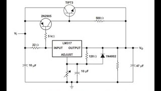
This circuit design needs improvement. The regulator will stop regulating the output voltage if the potentiometer is set to 5k ohms. For 17V output, the 270 resistor needs to be 397 ohms when using the 5k ohm potentiometer. If you intend to build this circuit beware! 🇦🇺


![LM317 Current Boosting Circuits [2N3055, MJ2955]](http://i.ytimg.com/vi/FItAwcsj0OI/mqdefault.jpg)


I have used this circuit for years. It works fine. Good load regulation. Can energize up to 5 amperes load. I use 6.8Ω and TIP36 with large heatsink.
@ibles bosuok..
Where did you joint the 6.8ohm..at the lm or tp?
Upto how much ampere can we use on 2n3055 without damaging anything ?
I prefer 6.8 ohms for Rb, so the current threshold would be about 100mA.
Choose 390 ohms for feedback resistor, the maximum output voltage would be about 15V which convenient for many applications. You can supply with 18VAC secondary voltage.
Greetings from Indonesia
Great Video, Very Detailed. I am just messing around with a few boost, and buck converters I have purchased overtime. I have seen a few video's, explaining how to bypass the LM317/LM388 for higher current than what the chip allows. Couldn't you also bypass the limitation of the converter like the LM317 circuit in your video. Looks like you could do the same thing without fail. What do you think. For Example, I would be using a Buck converter with XL4005.
Cool little circuit... Thanks!
i like this idea,will this idea work the same with a lm2596 regulator?
Great explanation! Should point out that one issue of using a PNP transistor to boost the output of a three terminal regulator is that there is no short circuit protection and in the event when the bypass transistor fails the input voltage is directly dumped onto the load.
Good point I'll do a vid on circuit protection which I did in other vids. The same problem exists with the LM317 alone. Thanks.
Yest you are right . For information , I have tried both solutions, the LM317 has temp and internal current protection of 1.5A. I just got 10pcs($1) from TK Electronics 99.5% on Ebay , tested those (short output at 39V input)and believe it or not, not one failed! I use a lm431 to drive 6pcs lm317 resulting in a very very stable output between 0 and 9A
can i boost the current to 2A output??...
is this circuit having the short protection???
Hello Lewis, Thanks for your analysis, its great.. My question: Will the LM317 hold the voltage set . as we increase the output load current. It appears that the MJ2955 is paralled with LM317, I will try it nevertheless.
Should be close that is what my tests responded.
WHERE DID YOU GET 19.7V IF YOUR POWER SUPLLY IS 19.0V ?
Can I put somewhere a potentiometer to adjust the output current. If it's possible can you tell where i should connect it and what kind? thank you for this upload, you help me a lot to understand.
Not without a major redesign of the circuit. Sounds like you want a current limiter.
I know this circuit works as I have built it and seen it work, However, I still dont quite grasp how the voltage remains regulated at Vo with the Q1 in the current path..
I don't have any silicon pnp power transistors at hand but I do have a few npn ones. Could I mirror your transistor / Rb circuit on the output side of the lm317 with a pnp transistor? Thanks.
No you can't if you want a positive output.
hello Lewis loflin, if the input is 20V 2,4A, this circuit regulator isn't damage
The power loss in LM 317 is proportional to input output difference. for example if output is 5 v and input is 20 v with 0.5 amp current power loss in 317= (20-5)x 0.5 = 7.5 watt. u need big heat sink and fan. see my vidioes
great video
How well does it regulate through the transistor compared to an LM317 by itself?
There is some drift due to heating. This I use for general current limiting.
That was a good practical video, thanks. Once the current is such that the resistor develops 0.7 volts or so it turns on the transistor and now you can supply more voltage. I like these analog lessons.
This about current not voltage. The voltage drop depends on the load resistance.
Doesn't the transistor turn on when the voltage drop across Rb is about 0.7 volts, enough the forward bias the emitter resistor? I thought that was what Rb was used for.
The BE voltage stays around 0.7V once turned on because addition current flows from BC.
I have questions -
1) If I use an npn transistor and connect it's base to the regulator output , collector to the input supply and take final output from emitter and ground for drawing upto 3 ampere load, then will the output voltage have good regulation at all voltages I select ?
2) If I use your circuit with pnp transistor, will I need to put heavy heatsink on both the regulator and transistor or only the transistor ?
1) can't use a npn. Use a heatsink.
I'm not certain most of the Rb current would be going to the base-collector junction since the input of LM317 is absorbing all of the 10 ohm R current and the emitter-base current turning the transistor Q1 on.
If on the other hand the current flowing through 10 ohm resistor, would go to the base of PNP, (as explained in 3:39 ) Q1 would stop conducting. Other than that, your video is great, and very useful as usual.
Rb sets the current flow for the PNP transistor. When enough current flows through Rb, the voltage drop turns on the transistor, shunting excess current through the transistor.
Thanks for the great explanation. Is it possible to use 12V instead of 19V ?
Yes depending on the required output voltage. That is determined by the load resistance.
@@LewisLoflin I tested the circuit and it was worked fine, but the output of the circuit was shorted by mistake so then the transistor was failed. Therefore if it is possible to add mechanism to increase the current gradually, it will protect the transistor with high current surges.
@@neon-pl3du How much current are you drawing? You will have to read the transistor specs.
Outstanding video! I just built my first power supply using an LM317 and I wanted to increase the current capability so this info is exactly what I was looking for. Is there an easy way to calculate the voltage drop across Rb so you can select the correct ohm value?
That is tough. The voltage measured across Rb is the emitter-base voltage of the transistor. It will measure about 0.6V from a forward-biased junction. Note the current for the LM317 passes through Rb so big values of Rb might cause the LM317 to lose regulation. Use a 2-watt resistor. Don't use this to pull massive amounts of current.
Copy that. I'm sure it can be calculated though since it's similar to calculating the value of a resistor to obtain the 0.6v - 0.7v bias needed for any transistor, except in this case we're trying to make a difference in potential between the pcb trace at the transistor base and the trace at the emitter. I'm thinking if we can calculate the total resistance we can find the current, and since we know the voltage at Rb we can figure out the amount of resistance needed to obtain the small voltage drop we need to turn on the transistor. Like you said also, we don't want too large a resistance or we'd be removing the LM317 from the equation altogether.
@@LewisLoflin P = U^2 / R. Considering Urb will never be bigger than 0.7V (forward voltage BE) (0.7)^2 / 10 = 0.049W - why use 2W resistor?
@@zyghom All of the current for the LM317 itself passes through this resistor. I also happened to have 2 watt resistors. Smaller should still work.
@@LewisLoflin that is ok but there is a difference between: "we need 2W resistor" vs "I happened to have just 2W resistor". If we consider the voltage on this resistor cannot go above 0.7V (as there is a E-B "diode" like forward voltage) then there is no need to have such big one. So either I am not getting the point or... ;-)
Hello, nice video ! can it also work with a TIP36c transistor ? the MJ is not available around. Thanks.
You can use any PNP bipolar transistor beware of collector current.
Will a 2SA1302 work instead of the MJ2955
As long as it is a PNP. It is 2SA is a PNP. Please keep in mind the current rating.
Why the voltage in the input is not dumped to the output voltage when the transistor is on?
The transistor passes current. Voltage is set by the LM317. The transistor current is controlled by the LM317 current and resistor RB.
i like the explanation you use but what is the purpose of the transistor if we get 1A out fro 1A in.
If you use more than an amp the excess current is carried by the larger transistor.
10Q
where is the current limiting resistor for the base? if the lm pulls enough current base current will overdrive and might destroy the tran.
The LM317 doesn't pull current through the base the voltage drop across R does. That type transistor can take a lot of current.
the LM is a magic auto-adjusting resistor, forming a voltage divider with Rb that always balances to 0.7v, given a reasonable input voltage and load resistance.
I wonder why not using a 2N3055 after the lm317 and spare the resistor and the power it dissipates?
Is there any special reason to use the 2955 and the resistor?
2N3055 is an NPN. This is a current boost and requires a PNP.
How can you have 19.7 volts on a node, when there are only 19.0v input.
It's an illustration. the input was 19.7. Thanks.
I can't figure out the mechanism of which the output voltage is still regulated. Since the input voltage is passed across to the output through the transistor.
Did you got the reason why it’s still regulated on the output? I tested it and it works even on higher current, I just don’t get why it works, shouldn’t the on transistor act like a “path of least resistance”? I don’t get why it still gets regulated…
@@KelvneMachado Don't know. Just have to accept that it just works
I’ll look further on a local university, if I find a professor willing to explain, I’ll explain here, maybe even make a video about it, no one explain that on any video
@@KelvneMachado Maybe a few sentence to the point is enough to clarify it?
How to use this circuit if a negative regulator Lm337 is used for negative voltage ?
Use the LM337 but change the transistor to an NPN, reverse all the caps, etc.
can I use 2n3055 instead of MJ2955
Learnings... , you can use 2N3055 with an LM337
Greetings from Indonesia
Can you post a circuit with 2N 3055 transistors please...
You can't use a 2N3055 in this circuit. The circuit would be a total redo.
can you provide me the ckt where we can use 2n3055 pleaseee
I'm doing a circuit on this and will post it soon.
The transistor only works when voltage drop across Rb resistor is greater than 6V. Why it does not turn on when voltage drop becomes 0.7V? I am using load of 5W 10 ohm resistor. Below 5V drop transistor does not conduct and all current passes through regulator. My Rb resistor is 3 ohm 7W and transistor should conduct when current greater than 0.2 A passes to allow 0.7V drop.? Please help
No it works at about 0.7 volts.
@@LewisLoflin The transistor conducts when voltage drop in Rb resistor geta above 7 why is that?
It's what the BE does when it conducts we get collector current. The 0.7V is can be a little higher or lower in the real world.
LM317 is so good. someone should make a better high voltage 5 pin lm317 with external mosfet driving capability.
What about protect Ic path (BJT transistor) ? LM317 protect himself but BJT doesnt't have protect. You must add one transistor + resistor to protect
One can do that but it works well as is. I used a current limiting resistor in one design. i was inserted between the transistor base and the LM317 IN.
Sir I have two questions.....
1. How can I use npn transistor replacing pnp
2. For cooling purpose what should I use /
Let me get what you saying here a pnp transistor is amplify current I get that but what I don’t understand is pnp is trigger by negative voltage but am seeing positive connection directly to its base no positive way the transistor can turn on and less there’s a npn that is sinking the current on the 10ohm resistor to allow negative voltage so please tell me what’s going here
There is no "negative" voltage there is a voltage difference across the base-emitter junction. The base-emitter current, controlled by the LM317 is amplified by the transistor beta rating.
@@LewisLoflin ok so there is negative current from the lm317 I see now
can we use mje 2955
Yes it will work. If drawing a lot of current heat sink the device.
Perfect video outstanding
Can use paralel transistor to make more current ??
does lm317 take more heat more when the transistor is on ???
I would not do that.
what is the pnp voltage drop ?
Voltage input minus the voltage across the load.
Can we use bd249c?
No that's an NPN transistor.
Using NPN 2N3055 the collector will be input voltage and emitter will be the output voltage and just omit the 20 ohms resistor at base of MJ2955 currently connected and you can add ballast resistor .1 ohm 5 watts between emitter of 2N3055 and output if you want to use two or more 2N3055 for higher current 10 ampere or more.
I have solar panel which gives output 7v 100ma will this circuit will convert it to 1000ma?????
You don't need this for 1 amp use the LM317 circuit by itself. Make sure it is well heatsinked.
Wait a minute - what are you using a 7-volt panel for?
Charging a battery
@@LewisLoflin I want to increase current
I am using solar panel for charging a battery
@@ankamanirudh8837 You have a 7-volt panel what is the charging voltage needed?
Can I use p Chanel mosfet in this circuit?
No. Transistors are current operated and MOSFETs are voltage operated.
@@LewisLoflin thank you very much sir, another question is, what should I do to achieve solar charge controller through this topology? (my target is to achieve 30 amps) pls help, your video has been a great help to me.
i can use 19v 3amp
Yes.
can I make same circuit with replace lm317 by lm338
The LM317 and LM338 are identical, except the LM338 is 5A. Yes.
@@LewisLoflin I tested one LM338 but it did not give me 5A at the output. What is the reason?
It has current limits due to heat. Never operate any device at max. In general no more than 80% in my opinion. What is the voltage going in versus the voltage output? Using a pass transistor distributes the heat. Use a good heat sink.
Also make sure to use input-output bypass capacitors.
Lewis
I made this circuit but 10 ohms resistor was burned.
Why?
What was the load? What wattage was the 10 ohm resistor? Are you sure you wired it correctly?
@@LewisLoflin
Load=Halogen Bulb 100W 12VDC.
@@LewisLoflin
1 Watt resistor 10 ohms
Learn BOX what transistor are you using? Do you know the actual beta? Try a much smaller load to make sure it is working.
@@LewisLoflin
MJ2955 Beta is 100
Nice keep on
Hello!
I am following your channel and reading some of your articles since yesterday! I find your projects diverse and interesting. Moreover i am searching for such detailed and tidy information about the current topic.
For a few hours I am trying to understand your circuit but i don't have the required experience and knowledge, so please excuse my profanity.
I think i understand the most except how is the output voltage from collector remaining the same as the output of the regulator.
Please if you are so kind!
Thank you very much!
The collector current for the transistor depends on the bass emitter current and the voltage from Rb. Current is not voltage, voltage is generated from current through a resistance. The more current though the LM317, the more through Rb, more current through Q1.
@@LewisLoflin thanks for replying me i feel glad to talk to you! After passing the circuit on simulation i see that the output voltage is regulated even if Q1 emitter is fed with voltage from the voltage supply. I will build it but i don't understand the magic how Q1 collector connected to LM317 output, both together to ADJ share the same voltage level. Please if you'd like to explain how..it comes that voltage is regulated at output - same as LM317, current is passed to Q1. Crazy - current i understand how but voltage not
I see nobody else than the Operational amplifier inside the regulator.
LM317 2.5VDC with current limit of 1.8A please. Thank you in advance.
Correct that's why the transistor.
@@LewisLoflin Can you show in youtube how to set exactly 2.5VDC with current limit of 1.8A please.
The 2.5 volts is dependent on your load resistance at 1.8A This is a current regulator, not a voltage regulator. The input can be for example 10V and if the output is set to 1.8A the rest will take care of itself. But again, voltage is set by load resistance.
This circuit design needs improvement. The regulator will stop regulating the output voltage if the potentiometer is set to 5k ohms. For 17V output, the 270 resistor needs to be 397 ohms when using the 5k ohm potentiometer. If you intend to build this circuit beware! 🇦🇺
Yes it's a demo circuit.