Top 10 Easy Electronics Projects using NE555P Timer IC for Beginners

Вставка
- Опубліковано 16 лип 2024
- Hi ,
This video is a series of top 10 electronics circuits based on NE555 IC.
◾ Circuit diagrams - drive.google.com/folderview?i...
00:00 Into
00:07 The Dark Sensor
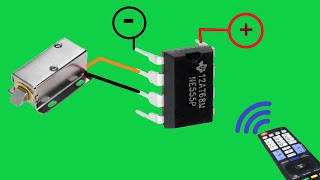
02:56 The Servo Controller
06:52 Buzzer with Speaker
09:09 The Brightness Sensor
12:50 LED Flashing controller
16:37 Dual Channel LED Controller
20:38 Touch ON OFF Switch
23:14 Long Press ON Circuit
26:22 Timer ON Circuit
29:48 LED Lighting Effect
◾ Buy NE555P - amzn.to/3h73r6h
◾ Buy 5nm LED - amzn.to/3kR01Ww
◾ Buy electronics kit - amzn.to/3yTXK1W
◾ Soldiering kit I use - amzn.to/2VBlCJN
◾ Camera I use - amzn.to/2X2k7Vn
◾ Other suggested videos -
1. Top 3 LED Chaser Projects -
• Top 3 LED Chaser || Ne...
2. Top 3 Transistor Projects -
• TOP 3 NEW TRANSISTOR P...
3. Top 5 Electronics Projects -
• Top 5 New Electronics ...
#ESTechKnowledge - Наука та технологія


![[NEW] Top 2 Useful Electronics Projects use NE555 Timer ic, Diy Projects](http://i.ytimg.com/vi/ZdHsxKY5C7c/mqdefault.jpg)


My dady 70 years oldman your project he is trying and win i am very happy ❤️🌹👍
buzzer with speaker is my fav project in this video..In this project we added many such push buttons along with the push button is series with resistors ...It turned out to be a beautiful musical piano ...Thank you so much for such wonderful projects..will be grateful..
I like but not vision and teks pin or pin where noumber 1 or noumber 2 not yet undesten
Last project is interesting 👍 Change colors blue and red.
Hepsi harika elinize sağlık teşekkür ederim
Good work
Thank you so much
Cool video! And thank you for the circuit diagrams. You are fantastic!🎉
Hello friend excelente Inventos Increíbles okay 😎🇨🇴🕊🌹🌹
Very good
Superb
excellent
Great one bro
Bhai video ak dum
Jehar hai
Thanx
Creative video, thanks :)
I love it, thank you, I will definitely use them
Good video
Cool
8. In the project, is there a chance to make a circuit that opens and closes automatically when pressed 2 times within 3 seconds instead of holding the button down?
я поставил лайк ровно 1000)))
Good work 👍
Nice
Podia passar o ESQUEMA depois de cada circuito.... Mas... Ganhou meu like.
I once saw plans for a radio using a 555
2:30 It's not really worth using a 555 timer for this circuit, just use any NPN transistor, check the pinout and match it to some other videos. There's a whole lot of them out there!
best
Aap video ke liye 👍
Top!!!!
Hi brother,can make a circuit for glow plug timer using 555?
It needs to be turned off after 5seconds time or adjustable timer.when the input power applied it should turn off output after set time by pot.but input power to the circuit remains on.
Simply off delay timer with a push to on switch,(not a push button switch)
I really like your videos. I have two questions. How hot is your iron? Do you have electrical schematics for your project? I am knew to all this, and when you fli[ the board over and start doing connections, I get lost. :(. A schematic would help lots. Thanks.
In second can I control a solenoid with it
Be sides no ten others are for children and good soldering you did!
you missed the point...
the LEDs can be replaced with OTHER things... like motors, servos, etc.
these are just projects to get ideas from, not to actually build..... unless you are 9.
also, many are actually incorporated in everyday appliances, like the touch sensitive switch, and light activated (photo-sensitive) lighting. your phone or tablet or tv uses it to dim the screen at night.
so they arent useless toy circuits.
3:20 Is that a 33KΩ or a 3.3KΩ Resistor??? I don't want to mess this up. Can you please tell me which??
Wow, great video. Where did you get the thin wire to solder to the circuit board? Thanks!
That's a single string of a 1mm wire.
@@estechknowledge Thanks.
@@estechknowledge Why ne555? Only one BC 547 transistor and one resistor, and working...
you call a "zero pcb" a perfboard. a "dark sensor" can be used as a flashlight but more efficient
Magically soldered as you insert them. Where do I get that type of board ?
Amazon, Alibaba, etc. Very inexpensive, too. :-)
In some local electronics shop ,ask pcb
@@ragupathis3406 ask for zero pcb
lol none of the answers to this get the joke
LM358, pls!
There's people who make living just making 555 circuits. Doesn't matter what you need, they will build a 555 circuit for you.
What you need
Make 4 led chaser
Ah get some modern 558's!
Hello, I like the no.10, it is ok to use 4 leds only? And, for 3v to 3.7v battery as my supply?
Using 4 leds only is fine. You may need to adjust the resistor values for brightness. 3.7v is fine. Red LEDs are rated at 5V reverse voltage. Just make sure to connect it the right way round
@@NickBarban thank you for the reply. Well, I already made it. 👍
Sir pls schematic diagram add this vedio .very use full hat diagram .thank you
Nice video sir.
23:14 Long Press ON Circuit
I need to trigger under 1 second, in this case what should I do to discharge the capacitor fast...?
thanks.
You can use a lower value capacitor or you can change the 555 IC 6-8 pin's resistance.
@@estechknowledge it doesn't matter in this case either because; I have to leave the button on for 800 milliseconds and off for 200 milliseconds, I have to finish the discharge process in 200 milliseconds after the first charge, is there any other way...?
So, why was the 555 necessary for the first circuit?...
He got a pcb board finally
Please skema number 2
At 3:19 that's pretty clearly a 3.3K resistor, not the 33K that the captioning shows.
true.... so true, ha! I wonder how many people messed that one up.
Falta el diagrama del circuito
Very little fonts write in big fonts
shematjcs please!
It's download link is available in the description of the video.
What do you use for the 4v power supply in your projects? Would a 3.7v battery work?
probably :) try it
অন্ধকার হলে আলো জ্বলে ওঠা ওটা করার জন্য LDR টাই যথেস্ট 555 IC ছাড়াও হবে
how much if i buy your diagram i like your simple projects
Bro i make the 10th one but from where can i get 5 colt dc supply , can you please tell me the easy way to get 5 volt dc plss😢
Phone charger dumass
A gdzie schematy?
I want to purchase a project
Bro got the hood irony intro 💀
I request you to please provide the respective circuit diagrams.
Available in the video description
Has anyone figure out yet how circulation pump motor works? I know it uses gate driver in IC to drive gates in IGBT. It is 3 phase too. pump name Wilo made in sweden or something. Same shit is in those compressor heater/cooler, the fans are run by PMM thats driven by weird pwm using gate drivers and IGBT. I wan to make them run on 12 or 24v DC.
Any smart person here? I could even pay if you know where to tap the pcb.
Diagram please.
Top 10 Easy Electronics Projects using ATMEGA328P ?
жаль, что нет схем внизу видео
ua-cam.com/users/redirect?event=video_description&redir_token=QUFFLUhqa2lITnk3Mk5PV0NncDQxT0tKQkFtYVBkSW9SUXxBQ3Jtc0ttTHp2dGhRdEc5bFhya3dXcDBFQk1QVUNWTlhqTU9NcDRhRWRXNUZQY1N6MGNqcDl0TzNxM2JCZFRyeDI2Z1BjNEo2b1l4Nk5aenlvT2dDMXFCMndkcEZaZ2R5cURacVBmSEJweGNsdGxURHZCMjFfNA&q=https%3A%2F%2Fdrive.google.com%2Ffolderview%3Fid%3D1RnBLTa_8XZPD3nN-Ts9ucohFARZKChtx&v=x-dt85j9Q10
Hi
Ur projects are great I need 1 help if you can.
I want to make a circuit out of 555timer adjustable using pot for 10 to 60mins interval.
Can you help?
Thank you.
This video might help you - ua-cam.com/video/1yj680JdZaU/v-deo.html
For 10-60 minutes replace the capacitor with 470uF and use a 1M preset.
Нарисуйте схемы пожалуйста или ссылку на схему напишите!
ua-cam.com/users/redirect?event=video_description&redir_token=QUFFLUhqa2lITnk3Mk5PV0NncDQxT0tKQkFtYVBkSW9SUXxBQ3Jtc0ttTHp2dGhRdEc5bFhya3dXcDBFQk1QVUNWTlhqTU9NcDRhRWRXNUZQY1N6MGNqcDl0TzNxM2JCZFRyeDI2Z1BjNEo2b1l4Nk5aenlvT2dDMXFCMndkcEZaZ2R5cURacVBmSEJweGNsdGxURHZCMjFfNA&q=https%3A%2F%2Fdrive.google.com%2Ffolderview%3Fid%3D1RnBLTa_8XZPD3nN-Ts9ucohFARZKChtx&v=x-dt85j9Q10
Обычно они есть в описании видео!
OK. So why do I cringe when I watch him solder?
Lol, same
Don't watch wtf man
Falta el diagrama de los circuitos
Geheim
@@wolfgangn4491 gracias 👍
@@wolfgangn4491 Gesundheit. I drive an Audi S5. I love it!
But bhai aap thoda video ka speed bdha ke dalo feer dekho . Kyo ki aapke subscribers sayad boring feel karte honge. Bura to nahi manoge mere comment ka. but try kar ke dekhna . aap apni video khud dekhna ak bar .ok
Ofcourse I also feel my videos belonging.
But I don't make videos so fast because, If someone wants to make this type of circuit then he/she can make the circuit with the video, that can help much better understanding the connections and wireing.
y el diagrama de los circuitos???....que somos?....adivinos?
If you are asking for diagram. It is available in the description of the video.
Please ad the circuit digram
Available in the video description
Pls. You have to give a diagram. Thanks.
Available in the video description
👍🔥👏👏👏👏👏👏
А.принципові схеми де.
Available in the video description of the video
не работает схема
26:22 Timer ON Circuit
Where can you buy parts whose pin you just insert into the hole, and on the other side it automatically cuts to size and solders itself in? 🤣 😂
the music makes the whole video annoying to watch.
The music to distracting, unnecessary and too loud.
No schematics mean no subscription from me. Sorry.
Available in the video description
internet sangat buruk, muter2 trs
Pas de schéma électrique explicatif
No circuit diagram, it's wastege of time and data
Available in the video description
Without schematics and component identification this video is worthless to the electronics hobbyist!!!
Why this annoying background music, though?
O que adianta mostra tudo isto ,se não tem esquemas
Cadê o esquema ,cadê o esquema cadê 0 esquema
*((((( MUY REDUNDANTE, CANSADOR,(((Y ABURRIDO))),EL VER EN TOOOOOOOOOOOOOOOODOS LOS PROYECTOS,COMO SE HACEN LAS SOLDADURAS,UNA OBVIEDAD.QUE DEBERIAN HABERLA SORTEADO DEL VIDEO))))*
According to this vid ne555 is pretty useless. Which is not the case.
идиотское видео схем нет просто один бред
Pointless unless you're explaining what you're doing, why you're doing it, and showing circuit diagrams, and details.
Component ka value,number kuchvi nehia bataya. Bekar video
Check out the video description
Very very unpolite and annoying to be asking evert 2 minutes to subscribe. You don't get. Sorry
NOTHING SPECIAL HERE AND NOT ONE SCHEMATIC
Available in the video description
Mille volte meglio fare i montaggi a volo che queste schifezze nelle millefori
Crap