This is a really, really good video man. I've dealt with PLLs at work but always as a mysterious black box that somehow keeps track of time and I never really understood them. It just so happens I've been researching QAM/OFDMA in order to figure out some symbol rate schenanigans, and I got to wondering how they actually detect phase in the first place. Which led me down the rabbit hole and to your video. Now the circle is complete :)
That's interesting! I'm coming at it with similar curiosity of "how's this magic box doing this?" But from eurorack synthesizer modules. A PLL is one of the best "strange tones for low cost", unconventional modules available.
An excellent introduction to PLLs and nice practical demonstration of (digital) phase detectors! I hope we'll see a video about VCOs as well :). Also, a great continuation of this topic are "charge-pump" PLLs, which are more popular in integrated circuits.
I do plan on continuing to make PLL related videos, first look at the other components and implementations, like VCO's; and then look at final use cases.
Oh and also note that PLLs can lock onto higher and lower frequencies with a type-1 phase detector. If there’s some relationship like f/2 or 3f/5 or something that causes the output signal of the phase comparator to repeat, then it’s a stable configuration for the PLL itself. This means if the rest frequency of the VCO is more than ~1.6 times the input frequency (ideally it’s a factor of 2), it won’t lock on that frequency but on a harmonic of it. Probably fine for FM radio, but for AM radio or audio purposes, this is a deal-breaker. I’ll have to see how the type-2 sims. Also neat function generator.
The fun thing with XOR ports is that one could make a PWM signal/generator by changing the phase or delay of the signal. You could even use sine waves as inputs.
Does it mean that the second type phase detector can detect only 5 angles 0,90,180,270,360 so if i need a detector that have 180 steps from 0 to 180 degrees which means he can read the shift degree by degree and gives me a reading on 25° different from 36° for example what to do please any one help
This is what I do not get. In Type I detector, when everything is aligned, you get 0 volts after low pass filter, basically putting VCO control voltage at 0 volts. How does this not revert VCO output frequency corresponding to ground and subsequently losing lock (given that input frequency is achieved at some non-zero control voltage)
hey my friend I need to make a square signal that have not any small changes in frequency or pulse width but ics like 555 timer can not be like that and have small changes is there any way???
Hello, I have built the same circuit of the PFD, but I had some errors and I couldn't simulate the Ckt, the error is "small size step" What's the problem cz am beginner with LTspice, Can u help me here?
I have some doubts about simulating transformer in LTSPICE. Primary voltage is rectangular waveform of 25Khz and 30% duty cycle. But when coefficient of coupling is less than 1, output waveform is not rectangular. It is converging to 3V. I want to know what is model of transformer in LTSPICE?
Nice video! 👍🏻 Btw, there are ideal filter blocks available for Ltspice. They work so much more convenient, especially the higher order ones (including highpass, bandpass etc).
I just noticed the warning that I haven't performed the updated in ~500days; more than half an hour later I remembered why I don't perform those updates. Anyway, I noticed the "Filter Products" category, that contains various IC's. Was this it?
@@FesZElectronics yes, updating always takes very long. The filters are in the SpecialFunctions category. But I really can't remember if it's by default or some kind of extra (I always just copy the whole folder to a new system). I will have a look for you :)
I found them now! These are default, but they came in a "recent" update (sometime in the last 500 days). Thank you for telling me about them, I will study them in more detail.
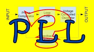
I love combining knowledge into not so many words... So! The stable crystal oscillator's sine wave is made to a stable voltage. Another voltage is fed to a voltage controlled oscillator who's function is affected by user voltage input and desired output frequency. To check if the desirable function is in phase, the multiplied function is divided to the base sine and compared? I need someone to check the validity of my statement.
Hello, I'm confused why the XOR based PLL locks when there is 90 degree phase shift between input and output. In other words, why locking occurs at half the voltage? What decides that?
I guess I didn't add the "D" input to keep the schematic simple, but this is a valid point - its important to see that input connection to get the circuit to work correctly.


Friendship ended with type-1 pfd, now type-2 pfd is my best friend.)
Thank you for explanation and especially for visual demonstration!
This is a really, really good video man. I've dealt with PLLs at work but always as a mysterious black box that somehow keeps track of time and I never really understood them. It just so happens I've been researching QAM/OFDMA in order to figure out some symbol rate schenanigans, and I got to wondering how they actually detect phase in the first place. Which led me down the rabbit hole and to your video. Now the circle is complete :)
That's interesting! I'm coming at it with similar curiosity of "how's this magic box doing this?" But from eurorack synthesizer modules. A PLL is one of the best "strange tones for low cost", unconventional modules available.
An excellent introduction to PLLs and nice practical demonstration of (digital) phase detectors! I hope we'll see a video about VCOs as well :). Also, a great continuation of this topic are "charge-pump" PLLs, which are more popular in integrated circuits.
I do plan on continuing to make PLL related videos, first look at the other components and implementations, like VCO's; and then look at final use cases.
costas loop as well
Really nicely presented comparison, thank you Fesz
Now I understand how a type-2 phase comparator works
It’s really good
No more XOR gate for my planned modular synth
PLLs are cool
I'm happy this helped!
Cheers!
Oh and also note that PLLs can lock onto higher and lower frequencies with a type-1 phase detector. If there’s some relationship like f/2 or 3f/5 or something that causes the output signal of the phase comparator to repeat, then it’s a stable configuration for the PLL itself. This means if the rest frequency of the VCO is more than ~1.6 times the input frequency (ideally it’s a factor of 2), it won’t lock on that frequency but on a harmonic of it. Probably fine for FM radio, but for AM radio or audio purposes, this is a deal-breaker. I’ll have to see how the type-2 sims.
Also neat function generator.
Interesting topic. I hope you make also a video with a complete ppl in the Future. Thanks a lot.
very nice explanation 👌
Your videos are outstanding.
Very nice video!
We love this video. Good job, sir!
thank you very much, i used your osciloscope views for my graduation work
The fun thing with XOR ports is that one could make a PWM signal/generator by changing the phase or delay of the signal.
You could even use sine waves as inputs.
Contradictory ,most people uses PWM in create pseudo sine wave instead.
Merci! Very interesting.
Thank you. Great video
I'm having a tough time getting my phase detectors working as I don't think I'm modeling the "board falls down" correctly in LTSpice
Does it mean that the second type phase detector can detect only 5 angles 0,90,180,270,360 so if i need a detector that have 180 steps from 0 to 180 degrees which means he can read the shift degree by degree and gives me a reading on 25° different from 36° for example what to do please any one help
This is what I do not get. In Type I detector, when everything is aligned, you get 0 volts after low pass filter, basically putting VCO control voltage at 0 volts. How does this not revert VCO output frequency corresponding to ground and subsequently losing lock (given that input frequency is achieved at some non-zero control voltage)
hey my friend I need to make a square signal that have not any small changes in frequency or pulse width but ics like 555 timer can not be like that and have small changes is there any way???
Hello,
I have built the same circuit of the PFD, but I had some errors and I couldn't simulate the Ckt, the error is "small size step"
What's the problem cz am beginner with LTspice, Can u help me here?
Earthquake 6:06😱
Capture range and Lock range?
sir, which is useful in analog phase detection from audio mp3 files.
like arduino etc.
I have some doubts about simulating transformer in LTSPICE. Primary voltage is rectangular waveform of 25Khz and 30% duty cycle. But when coefficient of coupling is less than 1, output waveform is not rectangular. It is converging to 3V. I want to know what is model of transformer in LTSPICE?
Type two having issue pc3 is keep fluctuating
Nice video! 👍🏻
Btw, there are ideal filter blocks available for Ltspice. They work so much more convenient, especially the higher order ones (including highpass, bandpass etc).
Is this filter a default component in LTspice or is it a component that needs to be imported?
@@FesZElectronics default, might have been added in a recent update
I just noticed the warning that I haven't performed the updated in ~500days; more than half an hour later I remembered why I don't perform those updates.
Anyway, I noticed the "Filter Products" category, that contains various IC's. Was this it?
@@FesZElectronics yes, updating always takes very long. The filters are in the SpecialFunctions category. But I really can't remember if it's by default or some kind of extra (I always just copy the whole folder to a new system). I will have a look for you :)
I found them now! These are default, but they came in a "recent" update (sometime in the last 500 days). Thank you for telling me about them, I will study them in more detail.
Excelent video. Love the blackboard revelion part. Lmao
Elektor's 303 circuits.
Remind me to Garth Nash' Application Note 535
If you could please let me know which circuit simulator you have used for simulating CD4046B PLL
I did not perform any simulations with the CD4046; I just built the circuits I showed from the basic logic gate building blocks found in LTspice.
@@FesZElectronics Thanks
I love combining knowledge into not so many words... So!
The stable crystal oscillator's sine wave is made to a stable voltage. Another voltage is fed to a voltage controlled oscillator who's function is affected by user voltage input and desired output frequency. To check if the desirable function is in phase, the multiplied function is divided to the base sine and compared?
I need someone to check the validity of my statement.
Hello, I'm confused why the XOR based PLL locks when there is 90 degree phase shift between input and output. In other words, why locking occurs at half the voltage? What decides that?
damn, this video was good
💐💐
Fesz for President!
8:51 Sorry you call these D-type triggers, but they don't have a D input. Perhaps you should connect D and inverse Q on each flip-flop?
I see that in LTSpice you have connected D-inputs to logic 1. This is definitely better.
I guess I didn't add the "D" input to keep the schematic simple, but this is a valid point - its important to see that input connection to get the circuit to work correctly.
👍❤️
nice shirt
when the board faal down 😂😂
Friendship ended with type-1 pfd, now type-2 pfd is my best friend.)
Thank you for explanation and especially for visual demonstration!