i think you should include the Rth ; you cannot calculate if you dont have Beta value. Rth= 1.8kohm, your equation should be Ve=0.7-1.8+1.8kIb Ve=1k(Ie)=1k(Ic+Ib)=1k(Ib)(B+1); 1.8k(Ib)-1k(Ib)(B+1)=1.1;
pls note that Ib is zero is based on condition that Re*beta/10 is bigger than 2.2k. if cannot satify it, use thevenin eqivalent circuit for accurate answer. learn from other youtubers.
I think Vc is not calculated correctly. we will make it like that --> Vc = (3.6k)x(1.1mA) - (-10) "which is the mistake that the 10 will be + 10 as -(-10) not -10 as written"
Enigma758 his idea is +(-10)=- 10. just the convention problem so it is no problem. for me i will write it as Vc=-10 + Ie*3.6k. you can think Vc= -6.04v is reasonably correct.
Why did you use -10volts. What circuit has -10volts. Why couldn't you use a more bring to earth circuit with +10volts on the Emitter side and a load connected to ground on the collector side to explain this PNP transitor? Why al this know it all youtubers try to confuse the viewers?
PnP circuits would have -10 volts. If you wanna bring the ground to +10 you could do so and probably get the same result in the calculation. But in the reality a circuit with a PnP transistor will usually be set up like this! For example an audio amplifier system can have one set of npn transistors that amplify the sound when the waveform is above 0V. And one set of pnp transistors that amplify the audio signal when the waveform is below 0V. The circuit will be set up with two sources in series and the ground in between them. That way you get one side positive supply voltage for the npn transistors and on the other negative supply voltage for the pnp transistors.
No, the current is always positive, but if you get a negative number for the current it is nothing to worry about. Why? Because that means that your prediction of the flow of the current was opposite (it flows in the other direction). In this case he got positive number for the current because for every transistor we now in which direction the current flows. If you have a problem with a circuit with just resistors and sources just draw the flow of the currents on the circuit and don't worry if you get a negative number. As I said it will just mean that the current is flowing in the opposite direction and leave it as it is. Don't change anything because you may mess the circuit and get wrong results.


i think you should include the Rth ; you cannot calculate if you dont have Beta value. Rth= 1.8kohm, your equation should be Ve=0.7-1.8+1.8kIb
Ve=1k(Ie)=1k(Ic+Ib)=1k(Ib)(B+1); 1.8k(Ib)-1k(Ib)(B+1)=1.1;
Thank you so much for your instruction. It was so helpful in so many ways. Thank You and God Bless.
Excellent Zahi Haddad. As always!
You are awesome. Thanks 🙏
Excellent.
I LOVE U SO MUCH , this is exactly what i was looking for
Excelent content!
Thanks, remind me of my electronics classes.
Thank you.
Thanx man!...saved my day
pls note that Ib is zero is based on condition that Re*beta/10 is bigger than 2.2k. if cannot satify it, use thevenin eqivalent circuit for accurate answer. learn from other youtubers.
What model transistor is this? What is the hfe (gain)? Still, great instruction.
Thanks,
you missed Rth, it has to be included in your circuit
U can't divide voltage considering only 10k and 2.2k. Because there is a portion of transistor parallel to 2.2k resistor.
this is the short-cut approximation. not the exact analysis with thevenin. You should add these informations to your video
Why draw it upside down. We want the positive on top, just looks weird
I think Vc is not calculated correctly. we will make it like that --> Vc = (3.6k)x(1.1mA) - (-10) "which is the mistake that the 10 will be + 10 as -(-10) not -10 as written"
Yes, I believe you are correct.
Enigma758 his idea is +(-10)=- 10. just the convention problem so it is no problem. for me i will write it as Vc=-10 + Ie*3.6k. you can think Vc= -6.04v is reasonably correct.
It's better to think before commenting. Ic = (Vc - Vcc)/Rc and hence Vc = IcRc + Vcc or IcRc - 10V
VRc= Vc-(-10) ⏩. Vc= VRc - 10🎉
Worst Mic, but Best Explanation
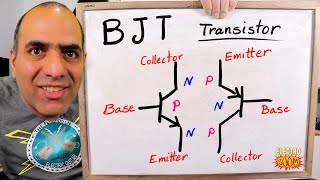
Differentiate between NPN and PNP transistors. According to you which one is going to switch faster.
Why did you use -10volts. What circuit has -10volts. Why couldn't you use a more bring to earth circuit with +10volts on the Emitter side and a load connected to ground on the collector side to explain this PNP transitor? Why al this know it all youtubers try to confuse the viewers?
PnP circuits would have -10 volts. If you wanna bring the ground to +10 you could do so and probably get the same result in the calculation. But in the reality a circuit with a PnP transistor will usually be set up like this!
For example an audio amplifier system can have one set of npn transistors that amplify the sound when the waveform is above 0V. And one set of pnp transistors that amplify the audio signal when the waveform is below 0V.
The circuit will be set up with two sources in series and the ground in between them. That way you get one side positive supply voltage for the npn transistors and on the other negative supply voltage for the pnp transistors.
Because the output would still be the same
Voltage is simply relative. You could have +10v on top terminal and +20v on bottom and the results would be the same
Can the current be negative?
No, the current is always positive, but if you get a negative number for the current it is nothing to worry about. Why? Because that means that your prediction of the flow of the current was opposite (it flows in the other direction). In this case he got positive number for the current because for every transistor we now in which direction the current flows. If you have a problem with a circuit with just resistors and sources just draw the flow of the currents on the circuit and don't worry if you get a negative number. As I said it will just mean that the current is flowing in the opposite direction and leave it as it is. Don't change anything because you may mess the circuit and get wrong results.
Life saver
I think you didnt do correctly because , you have to calculate RTH as well.
to much noise
What do you mean?
You were just solving without explaining anything