You’ve done excellent implementation of the PID equations to code lines ! Your work is indicating your electrical engineering deep knowledge ! Good job
Excellent demonstration and the walkthrough of the code was on point to me learn a few things... well, I always learning here :) I just checked your link and that motor is great for the price
Thank you very much form the great insight and content delivery on PID using arduino, You have simplified the equations and made them easy to get and play around with.
Nice work. There are not many videos out there detailing the controller implementation on systems. Did you feel the need for filtering the speed? I have been including a small window moving average filter to take care of small +-3 error in the encoder pulse count.
Hi and thanks! I haven't implemented it yet, but more professional projects almost always some sort of filter applied. I will probably discuss that in an other PID-related video.
Could you please disclose also, where did you get that grey craft mat on your table, with compartments for small parts? I have tried to find something similar in the internet, but without success.
Thank you so much for sharing this useful video. I have a question :if I want the motor to reach the desired position, with a certain velocity(eg. 2 rpm) what should I change in the code? Thanks
Hi! That is a bit more complicated because you want to rely both on speed and target distance. So, there are 2 variables. I think you should search for other tutorials because this one is only using one parameter at a time. It would be quite complicated to explain everything in the comment section.
@@CuriousScientist Hello, I tried it but when it comes to turning the knob it is very unstable, sometimes it stays spinning and does not stop, the position never returns to the target, maybe because I am using a TB6612 blue plate?
Thank you! I have some miniature DC motors (you can see it on my Instagram) and I want to make a precise positioning device with them. Also, PID is applicable for temperature control and I want to test a few things with that kind of controlling as well.
Hi! It is just a simple "textbook example". I didn't develop anything, I just coded the basic formulas. You can find them in any control theorem-related notes, books, or videos. Just use Google.
hello I finished the connection everything works very well, but I still have a question please, the encoding goes from 32445 to -32445, it is possible to increase the values? for example from 55000 to -55000 because I need the motor to do about 5 to 30 revolutions
Hey, would you mind explaining something to me? I need to implement a PID controller for a Uni project of mine. I don't understand how you can just simply take the control_signal (i.e. the PID result) and just supply it to the motor as PWM duty cycle - is it not possible that the control_signal ranges in different magnitudes? You always just cap it off at 255, but what if it moves in areas between e.g. 1,000 and 10,000? Is that not possible? I just want to understand why no "normalization" is necessary here
Hi! I capped it due to laziness and also due to the fact that I had a motor with a planetary gear which highly reduced the speed. If I normalize the values, I would probably get a very slow speed and it would take ages to reach the position. You can sure adjust and map the control signal (if the range is known) to your PWM resolution. Also, capping at 255 is due to the resolution of the PWM controller. Values above 255 won't make sense as it is out of the range of the possible PWM values. But this is where you can potentially map the control signal to the 0-255 PWM range. Alternatively, you can use a higher resolution PWM signal generator. I hope this answers your question.
why your code only works with a positive integer for target position and doesnt work for negative integer? this means motor can never achieve its target posiotion using CCW route. or this also means we can never have a two way reciprocatory position control.
I always try to stay positive. :} On a serious note, I never thought about the possibility of moving towards the negative range, so I just simply skipped it. I will look into it and come back to you in some days or weeks (I need to reassemble the system).
Just wanted to thank you on the excellent verbal explanation and well commented code. Question: per your example code, the motor speed starts at full speed (PWM = 255) is target is different than current by at least 255 count. I'm building an application where the motor will have some load and I would like to ramp up the speed gradually at some acceleration. I suppose I can add some code for the ramp up speed ? Also; if one uses a stepper motor in a PID application, would it provide a satisfactory result, since in with stepper motor the controller implicitly knows the position of the motor even though it's not a feed back loop. But I suppose you could use a PID but instead of AccelSteeper lib just use a standard stepper lib since the PID will calculate the deceleration to the target profile ? Would be great if you can add addition PID application examples in near future.
You are welcome, I am glad that you found the code and explanation useful. You can also make a PID control for the speed and you can tweak the parameters so it will reach the target speed slower. Or, if you go for the position, you can manually ramp up the motor, then let the PID take over when you reached the desired speed. Regarding the stepper PID, my personal opinion (which can be wrong of course) is that you don't really need a closed loop control for them. If the motor is skipping steps it means that either the power supply is not sufficient or the motor is undersized for the task. A well designed driving system with steppers might not need a closed loop control.
Hi! Yes, the encoder is on the motor's shaft. I would say, it is always like this in 99% of the servo motors (whether it is DC servo or hybrid stepper motor...etc.). Since you know the PPR value of the encoder (here, 11 PPR) and you know the gear ratio (here, 1:515), you can do the math easily based on the number of pulses counted and you can precisely tell the location of the geared shaft. For example, if you count 5665 pulses, it means that the motor did 515 turns which is -according to the gear ratio of the gearbox- will result in one full turn on the geared shaft. Or, you know that 5665 pulses is 360° on the main shaft, so one pulse is 0.0635° rotation on the main shaft.
@@CuriousScientist I understand you can calculate the desired rotation of the motor, but the (back)lash in the gears will define the accuracy on the output shaft. E.g. inkjet printers often use an dc motor with an optical encoder disc or strip, not on the motor shaft, but at the 'end-effector', e.g. the paper roller, or the print head.
Yeah, but they are usually lousy and cheap stuff. Generally, you have the encoder on the motor because the rest of the mechanism is built properly regarding backlash, stiffness...etc.
First of all, congratulations for your excellent work. I know of a chip that has the PID integrated, designed to control motors with an input for differential encoders. The LM 629 and 628. They are very expensive and with some changes to your software could be a perfect substitute for these chips. I have some doubts related mainly to the speed and precision at which your software can run. There are 500 pulses/turn encoders with two channels 90 degrees out of phase (differential). Therefore the precision is 1/(4x500) on the motor axis, because they use the four edges of the two encoder signals. At a speed of 2500 rpm there would be a frequency of 40,000 pulses/sec. Could the encoder be read at this speed with this Arduino? Even lowering the precision of the encoder would be a very high speed at which the position must be read. Could the reading speed be increased? Should I change the microcontroller? Another detail is that the LM 628 creates a speed profile to reach the position. My most sincere congratulations for your work. Best regards from Spain.
Hi! Thank you! 40000 pulses/s might be a bit too much for this little Arduino. You might want to use some ESP32 or Teensy 4.0 circuit, they are probably fast enough.
Sure, you just did it by commenting here. 😉 Otherwise, there's a contact form on my website, but please keep in mind that I am not a free support service. Cheers!
Hi! Yes, I did. Actually, if you watch the video carefully, I talk about a certain part of the code @35:00 where I explain that you can print the different parameters to check the PID. I came up with the three parameters I use in the video by iteratively changing them and checking the numerical output plus the behavior of the motor.
tenho uma pergunta se caso queira acionar dois motores pode colocar as fios conectados no mesmo pino, bom acredito QUE TALVEZ NÃO, se caso eu queira acionar o sentido de um motor girar para um lado e o outro para o lado contrario, no codigo seria necessário mudar além das primeiras linhas das declarações do motor a linha 79 teria que mudar certo, outra pergunta com esse driver para o motor você consegue acionar dois motor ?? , você fez o modelo matemático e depois achou esses valores de kp, ki kd (PID)?
Hello, thanks for the PID tutorial. On your website you call for 36SG motor which in your code has 11 PPR, whereas when you click on the link it takes you to motor 36GP which has 17 PPR. perhaps the motor you used in the demo is not available anymore? Can you please help clarify.
Hi and welcome! I bought the exact same motor, but for some reason I got it with a 11 PPR encoder. But it does not matter, you can easily adjust everything for any PPR encoder.
@@CuriousScientist Thanks for your quick response. Yes, I have figured what changes I would need to make in the code to support the 17 PPR encoder on the motor. Thx again!
How do you keep the position of the motor same on startup? for example if it is in a robot arm then how do you know the absolute location of the arm on startup. Wont the position be different every time the robot boots up?
@@CuriousScientist in that case y not simply use the feedback of the absolute sensor at the end of the shaft to control the position rather than use a encoder to count the pulses ? just curious
Because there are different applications. Sometimes you just need a relative position or only the speed so in that case you don't really need an absolute encoder. Absolute encoders are usually also more expensive.
@@CuriousScientist thanks for your insight. I am actually building a linear servo using a lead screw and getting feedback using a multiturn pot attached to the lead screw using a string and pulley running in parallel. I did a lot of pid tunning but it is hard to get the motor to stop at called position in the sketch. It either overshoots and then settles slowly after sometime of never reaches and keeps whining. Also the P value end up as high as 45 ( anything less the motor decelerated very slowly when it is near the target and ultimately stops short of the target ). I was thinking of maybe using a encoder on the motor shaft but that would not give me the absolute position . Any insight on a setup like this?
Every system has a different response, therefore you have to tune the PID for them individually. It is not a very easy task. Check one of my recent videos. I built a miniature linear actuator and control it with PID.
Hi, This is the best video I have found in controlling a dc motor with an endcoder. Very nice work. I have been trying to learn all of your code. I understand some of it, but not all. I would like to program in positions right into the code. Do you know how one would go about implementing this into your code? For example: Set a target position in the code, say one or two full turns of the output shaft, and stop. Do this by way of pushbutts. Press one button to move and stop. Then, press another button to return and stop. I think this could be very useful for a lot of people. To clarify, I would like to pre program in positions. Can you help with some information? Thank you in advance for any info you can supply. Sincerely, Bill Patton
Hi! Thank you very much! Of course I know. You have to translate the target position to the number of pulses detected by the encoder. The number of pulses is read on the shaft of the motor. So whatever you attach to the motor, you need to account for it. For example, let's say the motor does a full turn (360°) on the shaft and this is equal to 400 pulses. Then, if you have a 100:1 gear attached to the shaft, you will need to do 100 full turns on the motor to generate one full turn on the other side of the gear box. This means that you will need 400x100 = 40000 encoder pulses detected to be able to say that you have rotated the shaft of the gearbox by one full turn. So you just base everything on the pulses and you run the motor until X number of pulses are detected. You can create a "go-to" function that takes an argument as the target position. With each different buttons you pass a preprogrammed position to this function so the motor will move until you reach the position. Also check my other relevant video in this topic. It probably has the answer for your question: ua-cam.com/video/IUdAc9zp424/v-deo.html
Thank you for your fast reply. One thing I noticed on your electrical schematic. You have D3 on the hand encoder. It should be D2. No big deal, but I thought I'd let you know. Also, I watched your video from the link you sent. Are you allowing people to copy and play with your code? I did not see a link for the code. Again, thank you for your videos. I would like to help you, but I am 66, and I am on a fixed income. If you would consider helping me out with creating the code to make a test code that will have preset position values in the code and be controlled by an input. I would be happy to figure out a payment I could make with you. Please let me know what you think. PS. One project I would like to try is making blinds open and close.
@@Dekan88 You're welcome. Thanks for the remark. I see that the text is wrong, but the wiring is correct. I will replace the image when I have some time to edit it. The code for this video is available for free, it is on my website. The code used in the other video is also free. You just need to follow my explanation and write the code. Alternatively, you can support me on Patreon and then you can download the .ino file. If you want me to develop code for you, you can actually hire me for a gig. Use the contact page on my website.
Hi! What do you mean? Isn't Arduino Nano an "Arduino board"? As long as you keep the connections similar, you can use any Arduino-compatible boards (Uno, Nano, Mega...etc.).
I have no idea what you tried so far and where you might have made a mistake. It is hard to say anything without seeing your work... Furthermore, a DC motor is not capable of receiving commands. You need a motor driver. A motor driver is typically controlled via a PWM signal, which is generated by a microcontroller. I hope these clues help.
It depends on the application, but of course you can drive it with a PID. But why would you need a PID for a stepper motor? What's the parameter that you would like to control using PID?
@@CuriousScientist I'm on a project now that retrieves and pick up a land robot using a tether with a magnet at the end. I'll be using a stepper motor driven tether that is attached to the drone. Thus, I need the stepper motor to rotate a certain steps equivalent to a certain distance detected by the distance sensor. Making the rotation of the stepper motor critical so that the land robot won't be damaged. Your reply is very much appreciated.
@@CuriousScientist Hello sorry for all my questions .. little question, on the button in relation to the diagram ... on my button I have Key, s1, s2 . on the schema clk corresponds to key, sw corresponds to S1, DT corresponds to s2? thank you for your help
THANKS A LOT CAN YOU PLEASE POST VIDEO FOR THE (CONTROLLING OF DC MOTOR 'ACTUATOR ' PROGRAMABLE POSITION WITH MEMORY BUTTONS USING ARDUINO. BEST WISHES
You'll need to rewrite some portions of the code because the other driver needs both control pins to be driven by PWM (not at the same time, but when you flip the directions, you need to feed the other input pin with a PWM signal). I think the TB6612 is a bit simpler to use.
Good evening Sir , Can you tell me how to find the transfer function parameters , for example inductance , damping coefficient , inertia etc to design the transfer function
If I want to input the target manually in the code without using rotary encoder, what changes should I do for the code you are using? Please this is really important for a project I am working on. Thanks ❤


You’ve done excellent implementation of the PID equations to code lines !
Your work is indicating your electrical engineering deep knowledge !
Good job
Thank you very much! I try to learn and share as much knowledge as possible.
Great video especially the PID explanation within code for the Arduino. Thanks for sharing.
Thanks!
Excellent demonstration and the walkthrough of the code was on point to me learn a few things... well, I always learning here :)
I just checked your link and that motor is great for the price
Thank you! Yes, this motor is amazing. I also have another type of motor, I will show it in an upcoming video. ;)
Thank you very much form the great insight and content delivery on PID using arduino, You have simplified the equations and made them easy to get and play around with.
Thank you! The goal was to create a relatively easy-to-understand video on this topic. I am glad that you found it useful!
Thanks for making this video it does serve its purpose ❤ helping those getting into pid motor control.
Hi! I am glad to help! It was also a good learning process for myself as well.
Nice work. There are not many videos out there detailing the controller implementation on systems. Did you feel the need for filtering the speed? I have been including a small window moving average filter to take care of small +-3 error in the encoder pulse count.
Hi and thanks! I haven't implemented it yet, but more professional projects almost always some sort of filter applied. I will probably discuss that in an other PID-related video.
Could you please disclose also, where did you get that grey craft mat on your table, with compartments for small parts? I have tried to find something similar in the internet, but without success.
Hi! Go to aliexpress and search for "heat resistant soldering mat". Cheers!
Thank you so much for sharing this useful video.
I have a question :if I want the motor to reach the desired position, with a certain velocity(eg. 2 rpm) what should I change in the code?
Thanks
Hi! That is a bit more complicated because you want to rely both on speed and target distance. So, there are 2 variables. I think you should search for other tutorials because this one is only using one parameter at a time. It would be quite complicated to explain everything in the comment section.
❤this is the control to garage door operator
Hi! It can be used for anything that needs control. 😎
@@CuriousScientist thank you very much
You're welcome!
@@CuriousScientist Hello, I tried it but when it comes to turning the knob it is very unstable, sometimes it stays spinning and does not stop, the position never returns to the target, maybe because I am using a TB6612 blue plate?
Hi! The PCB color should not matter, it has the same chip. Maybe you forgot to tune the PID parameters, so the algorithm does not run properly.
This is a great video! Thanks for taking the time to share this experiment! What are you planning to build with this PID control?
Thank you! I have some miniature DC motors (you can see it on my Instagram) and I want to make a precise positioning device with them. Also, PID is applicable for temperature control and I want to test a few things with that kind of controlling as well.
Excelent! Just one question:
It’s possible to control constantly without the button press?
Thank you! Of course it is possible. It only depends on how you write the code.
Hello, can you explain how did you develop the transfer function of dc motor
Hi! It is just a simple "textbook example". I didn't develop anything, I just coded the basic formulas. You can find them in any control theorem-related notes, books, or videos. Just use Google.
hello
I finished the connection everything works very well, but I still have a question please, the encoding goes from 32445 to -32445, it is possible to increase the values? for example from 55000 to -55000 because I need the motor to do about 5 to 30 revolutions
Hi! Yes, just use simple mathematical formulas to convert the values.
Hey, would you mind explaining something to me? I need to implement a PID controller for a Uni project of mine. I don't understand how you can just simply take the control_signal (i.e. the PID result) and just supply it to the motor as PWM duty cycle - is it not possible that the control_signal ranges in different magnitudes? You always just cap it off at 255, but what if it moves in areas between e.g. 1,000 and 10,000? Is that not possible? I just want to understand why no "normalization" is necessary here
Hi! I capped it due to laziness and also due to the fact that I had a motor with a planetary gear which highly reduced the speed. If I normalize the values, I would probably get a very slow speed and it would take ages to reach the position. You can sure adjust and map the control signal (if the range is known) to your PWM resolution. Also, capping at 255 is due to the resolution of the PWM controller. Values above 255 won't make sense as it is out of the range of the possible PWM values. But this is where you can potentially map the control signal to the 0-255 PWM range. Alternatively, you can use a higher resolution PWM signal generator. I hope this answers your question.
why your code only works with a positive integer for target position and doesnt work for negative integer? this means motor can never achieve its target posiotion using CCW route. or this also means we can never have a two way reciprocatory position control.
I always try to stay positive. :}
On a serious note, I never thought about the possibility of moving towards the negative range, so I just simply skipped it. I will look into it and come back to you in some days or weeks (I need to reassemble the system).
Thank you!
You're welcome!
Just wanted to thank you on the excellent verbal explanation and well commented code. Question: per your example code, the motor speed starts at full speed (PWM = 255) is target is different than current by at least 255 count. I'm building an application where the motor will have some load and I would like to ramp up the speed gradually at some acceleration. I suppose I can add some code for the ramp up speed ? Also; if one uses a stepper motor in a PID application, would it provide a satisfactory result, since in with stepper motor the controller implicitly knows the position of the motor even though it's not a feed back loop. But I suppose you could use a PID but instead of AccelSteeper lib just use a standard stepper lib since the PID will calculate the deceleration to the target profile ?
Would be great if you can add addition PID application examples in near future.
You are welcome, I am glad that you found the code and explanation useful. You can also make a PID control for the speed and you can tweak the parameters so it will reach the target speed slower. Or, if you go for the position, you can manually ramp up the motor, then let the PID take over when you reached the desired speed.
Regarding the stepper PID, my personal opinion (which can be wrong of course) is that you don't really need a closed loop control for them. If the motor is skipping steps it means that either the power supply is not sufficient or the motor is undersized for the task. A well designed driving system with steppers might not need a closed loop control.
Am I correct in assuming the encoder is on the motor shaft before the gear train? Shouldn't it be on the output shaft?
Hi! Yes, the encoder is on the motor's shaft. I would say, it is always like this in 99% of the servo motors (whether it is DC servo or hybrid stepper motor...etc.). Since you know the PPR value of the encoder (here, 11 PPR) and you know the gear ratio (here, 1:515), you can do the math easily based on the number of pulses counted and you can precisely tell the location of the geared shaft. For example, if you count 5665 pulses, it means that the motor did 515 turns which is -according to the gear ratio of the gearbox- will result in one full turn on the geared shaft. Or, you know that 5665 pulses is 360° on the main shaft, so one pulse is 0.0635° rotation on the main shaft.
@@CuriousScientist I understand you can calculate the desired rotation of the motor, but the (back)lash in the gears will define the accuracy on the output shaft. E.g. inkjet printers often use an dc motor with an optical encoder disc or strip, not on the motor shaft, but at the 'end-effector', e.g. the paper roller, or the print head.
Yeah, but they are usually lousy and cheap stuff. Generally, you have the encoder on the motor because the rest of the mechanism is built properly regarding backlash, stiffness...etc.
Can I use a motor with a JGA25-370B type encoder and would it alter the code or would it remain the same?
Sure, these motors are built around the same principles. Check the pins on the motor, just to be sure, but it should be the same.
@@CuriousScientist It's okay, thank you very much, your project guide helped me a lot.
It is great to hear that!
First of all, congratulations for your excellent work. I know of a chip that has the PID integrated, designed to control motors with an input for differential encoders. The LM 629 and 628. They are very expensive and with some changes to your software could be a perfect substitute for these chips. I have some doubts related mainly to the speed and precision at which your software can run. There are 500 pulses/turn encoders with two channels 90 degrees out of phase (differential). Therefore the precision is 1/(4x500) on the motor axis, because they use the four edges of the two encoder signals. At a speed of 2500 rpm there would be a frequency of 40,000 pulses/sec. Could the encoder be read at this speed with this Arduino? Even lowering the precision of the encoder would be a very high speed at which the position must be read. Could the reading speed be increased? Should I change the microcontroller? Another detail is that the LM 628 creates a speed profile to reach the position. My most sincere congratulations for your work. Best regards from Spain.
Hi! Thank you! 40000 pulses/s might be a bit too much for this little Arduino. You might want to use some ESP32 or Teensy 4.0 circuit, they are probably fast enough.
Is there a way to get in contact with you regarding this video?
Sure, you just did it by commenting here. 😉 Otherwise, there's a contact form on my website, but please keep in mind that I am not a free support service. Cheers!
I sent you an email on your contact form
I replied.
good show but it looks as if you are loosing pulses in both directions so you may want to increase the pulses per revolution or maybe its the gearbox.
Thanks! Probably the gearbox, but I am not sure.
Great videos as always!
Thanks Stefan! I really appreciate your continuous support!
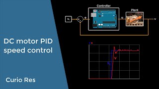
So, have you tried plotting the demanded position against the actual to assess the PID performance?
Hi! Yes, I did. Actually, if you watch the video carefully, I talk about a certain part of the code @35:00 where I explain that you can print the different parameters to check the PID. I came up with the three parameters I use in the video by iteratively changing them and checking the numerical output plus the behavior of the motor.
Sorry another question. Do you know of any commercial H-bridge that can handle more or less 25-30 amps and about 24 volts? Thank you so much
Sorry, I don't know about anything similar to that. Maybe ask Google or ChatGPT.
tenho uma pergunta se caso queira acionar dois motores pode colocar as fios conectados no mesmo pino, bom acredito QUE TALVEZ NÃO, se caso eu queira acionar o sentido de um motor girar para um lado e o outro para o lado contrario, no codigo seria necessário mudar além das primeiras linhas das declarações do motor a linha 79 teria que mudar certo, outra pergunta com esse driver para o motor você consegue acionar dois motor ?? , você fez o modelo matemático e depois achou esses valores de kp, ki kd (PID)?
Sorry, I don't understand what you are talking about. Maybe try again in English...
Hello, thanks for the PID tutorial. On your website you call for 36SG motor which in your code has 11 PPR, whereas when you click on the link it takes you to motor 36GP which has 17 PPR. perhaps the motor you used in the demo is not available anymore? Can you please help clarify.
Hi and welcome! I bought the exact same motor, but for some reason I got it with a 11 PPR encoder. But it does not matter, you can easily adjust everything for any PPR encoder.
@@CuriousScientist Thanks for your quick response. Yes, I have figured what changes I would need to make in the code to support the 17 PPR encoder on the motor. Thx again!
Nice to hear that you've figure it out! Cheers!
Thank!
How do you keep the position of the motor same on startup? for example if it is in a robot arm then how do you know the absolute location of the arm on startup. Wont the position be different every time the robot boots up?
Either I would perform a homing at every startup, or would use an absolute encoder on the part of the axis that doesn't rotate more than 360°.
@@CuriousScientist in that case y not simply use the feedback of the absolute sensor at the end of the shaft to control the position rather than use a encoder to count the pulses ? just curious
Because there are different applications. Sometimes you just need a relative position or only the speed so in that case you don't really need an absolute encoder. Absolute encoders are usually also more expensive.
@@CuriousScientist thanks for your insight. I am actually building a linear servo using a lead screw and getting feedback using a multiturn pot attached to the lead screw using a string and pulley running in parallel. I did a lot of pid tunning but it is hard to get the motor to stop at called position in the sketch. It either overshoots and then settles slowly after sometime of never reaches and keeps whining. Also the P value end up as high as 45 ( anything less the motor decelerated very slowly when it is near the target and ultimately stops short of the target ). I was thinking of maybe using a encoder on the motor shaft but that would not give me the absolute position . Any insight on a setup like this?
Every system has a different response, therefore you have to tune the PID for them individually. It is not a very easy task. Check one of my recent videos. I built a miniature linear actuator and control it with PID.
Hi, This is the best video I have found in controlling a dc motor with an endcoder. Very nice work. I have been trying to learn all of your code. I understand some of it, but not all. I would like to program in positions right into the code. Do you know how one would go about implementing this into your code? For example: Set a target position in the code, say one or two full turns of the output shaft, and stop. Do this by way of pushbutts. Press one button to move and stop. Then, press another button to return and stop. I think this could be very useful for a lot of people. To clarify, I would like to pre program in positions.
Can you help with some information? Thank you in advance for any info you can supply.
Sincerely,
Bill Patton
Hi! Thank you very much!
Of course I know. You have to translate the target position to the number of pulses detected by the encoder. The number of pulses is read on the shaft of the motor. So whatever you attach to the motor, you need to account for it. For example, let's say the motor does a full turn (360°) on the shaft and this is equal to 400 pulses. Then, if you have a 100:1 gear attached to the shaft, you will need to do 100 full turns on the motor to generate one full turn on the other side of the gear box. This means that you will need 400x100 = 40000 encoder pulses detected to be able to say that you have rotated the shaft of the gearbox by one full turn. So you just base everything on the pulses and you run the motor until X number of pulses are detected. You can create a "go-to" function that takes an argument as the target position. With each different buttons you pass a preprogrammed position to this function so the motor will move until you reach the position.
Also check my other relevant video in this topic. It probably has the answer for your question: ua-cam.com/video/IUdAc9zp424/v-deo.html
Thank you for your fast reply. One thing I noticed on your electrical schematic. You have D3 on the hand encoder. It should be D2. No big deal, but I thought I'd let you know. Also, I watched your video from the link you sent. Are you allowing people to copy and play with your code? I did not see a link for the code. Again, thank you for your videos. I would like to help you, but I am 66, and I am on a fixed income. If you would consider helping me out with creating the code to make a test code that will have preset position values in the code and be controlled by an input. I would be happy to figure out a payment I could make with you. Please let me know what you think. PS. One project I would like to try is making blinds open and close.
@@Dekan88 You're welcome. Thanks for the remark. I see that the text is wrong, but the wiring is correct. I will replace the image when I have some time to edit it.
The code for this video is available for free, it is on my website. The code used in the other video is also free. You just need to follow my explanation and write the code. Alternatively, you can support me on Patreon and then you can download the .ino file. If you want me to develop code for you, you can actually hire me for a gig. Use the contact page on my website.
hello, a small doubt ,can we do the experiment with an arduino board instead of arduino nano
Hi! What do you mean? Isn't Arduino Nano an "Arduino board"? As long as you keep the connections similar, you can use any Arduino-compatible boards (Uno, Nano, Mega...etc.).
Hi. Would you be able to control it with the nextion display?
Hi! Absolutely! 😎
Please could you help. I'm trying but I can't. I'm trying to make the nextion display send commands to a DC motor with an encoder.
I have no idea what you tried so far and where you might have made a mistake. It is hard to say anything without seeing your work... Furthermore, a DC motor is not capable of receiving commands. You need a motor driver. A motor driver is typically controlled via a PWM signal, which is generated by a microcontroller. I hope these clues help.
Can I send you an email with the material I used?
Yeah, but keep in mind that I am not a free support service. Cheers!
Can I also apply PID control on stepper? or encoder control in stepper motor is enough already?
It depends on the application, but of course you can drive it with a PID. But why would you need a PID for a stepper motor? What's the parameter that you would like to control using PID?
@@CuriousScientist I'm on a project now that retrieves and pick up a land robot using a tether with a magnet at the end. I'll be using a stepper motor driven tether that is attached to the drone. Thus, I need the stepper motor to rotate a certain steps equivalent to a certain distance detected by the distance sensor. Making the rotation of the stepper motor critical so that the land robot won't be damaged. Your reply is very much appreciated.
There's no PID needed for that.
will the code be the same if I use optical encoder instead of magnetic encoder ?
If the optical encoder produces the same type of output signal, then yes.
Hi
How can i modify it so i use a potentiometer instead an encoder?
Thanks in advance
Hi! Read the output voltage on the wiper of the potmeter using one of the analog pins.
Hello how Can i shift the display of numbers under Target and position ? Thanks
Hi! Try to watch the video. I explained everything in it, even your question. @35:25
@@CuriousScientist Thank you
@@CuriousScientist Hello sorry for all my questions .. little question, on the button in relation to the diagram ... on my button I have Key, s1, s2 . on the schema clk corresponds to key, sw corresponds to S1, DT corresponds to s2? thank you for your help
Hi! I don't know what button do you use so I cannot say anything for sure. But mixing up clk and dt won't cause any electrical issues, so you can try.
THANKS A LOT
CAN YOU PLEASE POST VIDEO FOR THE (CONTROLLING OF DC MOTOR 'ACTUATOR ' PROGRAMABLE POSITION WITH MEMORY BUTTONS USING ARDUINO.
BEST WISHES
Hi and welcome! Sorry, but I am not making videos for requests for free.
what will change if we use a bts7960 driver?
You'll need to rewrite some portions of the code because the other driver needs both control pins to be driven by PWM (not at the same time, but when you flip the directions, you need to feed the other input pin with a PWM signal). I think the TB6612 is a bit simpler to use.
Good evening Sir , Can you tell me how to find the transfer function parameters , for example inductance , damping coefficient , inertia etc to design the transfer function
Probably a relevant control theory book or video can explain this better than me.
@@CuriousScientist Thank you , for your reply but How did you got the transfer function here if you do not have the parameters
@@CuriousScientist you had to get the kp , kd and ki values from matlab right , and there what have you used for transfer function?
I simply started with some typical values and played around with them to get an acceptable behaviour.
Please could someone help me I wanna make a speed regulator for a vehicle and don't know how to start!
Google and ChatGPT.
how to find kp ki kd if we don't have the equation of the system
Trial and error.
You can add intergal windup protection. If the PWM hits +/-255 then don't add the current error to the errorIntegral.
Wow, thanks, I have never heard about this issue. Will learn a bit more about it and implement it in my next PID project. Thanks!
This is so nice.but how it will work for RC controlling
What do you mean?
Wireless remote controlling is possible? Is in the above method.
Of course, you just need to take care of passing the value wirelessly.
If I want to input the target manually in the code without using rotary encoder, what changes should I do for the code you are using?
Please this is really important for a project I am working on.
Thanks ❤
Hi! Are you expecting me to write a code for you, or what? You can get the answer if you check my other stepper motor-related videos.
Your voice looks like Cr7 voice 💀
What do you mean?
@CuriousScientist I mean your accent looks like Cristiano Ronaldo accent
You mean, it _sounds like_. 😄 Nevertheless, I am not Portuguese. It's just an interesting coincidence.
@@CuriousScientist yeah thx for correction btw