How To Make a Voltage Regulator Circuit Using Zener Diodes & SuperCapacitors

Вставка
- Опубліковано 31 січ 2020
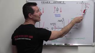
- This electronics video tutorial explains how to make a voltage regulator circuit using zener diodes and supercapacitors.
What Is a Diode? • What Is a Diode?
Full-Wave Bridge Rectifiers:
• Full Wave Bridge Recti...
Voltage Multiplier Circuit:
• Voltage Multiplier Cir...
Light Emitting Diodes:
• LEDs - Light Emitting ...
Power Dissipation In LEDs & Diodes:
• Power Dissipation In R...
LED Resistor Value:
• How To Select The Resi...
________________________________
Potentiometers - Variable Resistance:
• Potentiometers - Basic...
LED Dimmer Circuit:
• LED Dimmer Circuit - B...
Thermistors - Temperature Sensors:
• Thermistors - NTC & PT...
Zener Diodes:
• Zener Diodes
Zener Diode Solar Cell:
• How To Make a Solar Ce...
________________________________
Power Zener Diodes - Voltage Regulation:
• Power Zener Diodes as ...
12V LED Battery Level Indicator:
• 12V LED Battery Level ...
Reverse Polarity Circuit Protection:
• Reverse Polarity Circu...
High Voltage Surge Protection Circuit:
• High Voltage Surge Pro...
AC DC Polarity Tester Circuit:
• AC DC Polarity Tester ...
_______________________________
DC to AC Reverse Polarity Circuit:
• DC to AC Reverse Polar...
Varactor Diodes - Voltage Capacitors:
• Voltage Controlled Cap...
Final Exams and Video Playlists:
www.video-tutor.net/
Full-Length Videos and Worksheets:
/ collections
_______________________________
Zener Diodes: amzn.to/3icv8dB
Resistors: amzn.to/3B2jPNM
Alligator Wires: amzn.to/3icvnFx
250V fuse: amzn.to/3khxt9W
Supercapacitors: amzn.to/3iqjsV5
1N4007 Diodes: amzn.to/2U9HeMM
Disclaimer: Some of the links associated with this video may generate affiliate commissions on my behalf. As an amazon associate, I earn from qualifying purchases that you may make through such affiliate links.


![Lp. Последняя Реальность #97 ЧЁРНАЯ МАТЕРИЯ [Анти Скинт] • Майнкрафт](http://i.ytimg.com/vi/k4MjXCzKsYw/mqdefault.jpg)


In this video were gonna talk about everything your professors failed to talk about and were also gonna go over how without me your lives would be so much more difficult. Thanks so much again for all you do.
I love this guy as he is my family
The world's best teacher
Very logical explanation
Note that your discharge path does not have any resistor (aside from the Cap's ESR and the dynamic resistance of the zener). Therefore the discharge time would be much faster than the charge time. You should add a resistor in series with the caps to get more stability in the case of downward voltage spikes.
You are great Broh
I'm sorry but I can't understand how he determined the voltage at the point in the wire above the zener diode. That would mean that the voltage drop across the resistor is 0.3V does it not? When I created this circuit in the iCircuit app for macOS then I don't see the same numbers. Also, I'm confused. I thought current could not flow across a zener diode in reverse if the voltage was lower than 3.3 at the point before the zener diode.
When i listen i feel like i'm becoming an engineer
Please l have a problem of amplify ing a clap switch it's sensitivity is to low please help the world's best teacher
I wonder if you could hook another 1k resistor in parallel with the resistor but through a switch so while the switch is engaged the net resistance is 500Ω, allowing the capacitors to charge quicker. As the caps get close to 3.3v you could disengage the switch, removing the extra resistor from the circuit to maintain voltage stability. What are y'all's thoughts?
Yes, you could also connect the capacitors directly to the battery or your energy source and the charging would be faster indeed. The only problem of using smaller resistance is that the diodes don't support much current
What happen if diode zener kept on opposite direction in the circuit, thank for axplanation
Big fan
I want this with 24 volt input and 20 voltage out put.
how is he calculating the vout for a given vb?
Don't forget the load impedance.
Absolutely. Unless this circuit just delivers a reference voltage to a input with high impedance, the load will drain these super caps down. If this is a heavy load the circuit will not regulate very well.
wouldn't 2 10f caps in series like that act like a smaller cap... say 5f? as if the dielectric layer was thicker between the conductive layers? From what I understood it was when they are in series that you get a higher capacitance, at the same voltage... wait, no, now i see why they are in series, to get a higher voltage rating out of single lower voltage super caps...
i would have used a single 10F say 5 volt super cap (I don't know how they are set up voltage wise, i'm still learning about supercaps in general... PULSE caps, now that's my thing.)
Placing same capacitors in series increase voltage rating BUT the capacity will be the same. Capacitors behave exactly the same as battery with respect to series / parallel configuration.
I've studied a lot of these circuits and they all seem to be the same: They all have the resistor in line with the positive output terminal. This seems inefficient to me: you are always 'burning' current through the resistor, even if the Zener is not conducting. Why not have the resistor beneath the Zener diode, so that when the diode 'opens' the resistor limits the current that the Zener is having to pass and only drops the excess voltage across it? Have I misunderstood something? Thanks.
There seems to be a misunderstanding.
The thing with the resistor is that without any resistance the current would burn the wire, so the resistor regulates the current.
As for placing it below, you can imagine it like a line of people walking after one another in a loop, even if the resistor is placed below, the "people" will movr through the loop simultaneously.
i need a 6 votl ouput a 7.4 volts imput and load current of 500 mamps
how do i do
thanks
who are you???, how do u teach everything???
Why bother with these but instead use LM317T or L780 series voltage regulator.