Basic Calculations of Refrigeration Cycle

Вставка
- Опубліковано 7 лип 2024
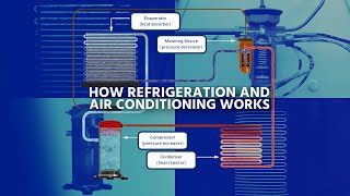
- Heating and cooling buildings accounts for 40% of total energy consumption in the U.S. This tutorial on refrigeration cycles steps through calculations needed to predict temperatures, pressures, and flowrates in a refrigeration loop.
Note: the video recording cut out about 1 minute before the end. The answers are:
1. From the evaporator, find the mass flow: 833 lbm/hr
2. From the compressor, find the work required: Ws = -15,000 BTU/hr
3. From the condenser, find the cooling rate: -75,000 BTU/hr
4. Check the overall balance: 0 = Qcond - Ws + Qevap = 60,000 - (-15,000) + (-75,000) = 0 - Наука та технологія


Thanks for this! You saved many Chemical Engineering lives! Appreciate this so much
Thank you so much! Professor doesn't use a projector for a 300 student class. The basic idea is drawn by hand on chalk boards, really didn't help at all. This is so great!!
Very useful and helpful sir. I'm ME student currently taking refrigeration and air conditioning and this is nice to see!
Hi I am sunil chopdekar Civil structural Engineer , done HVAC from SIT mumbai after taken traiing in August 2016, I could understand your explanation nicely on PH graph. Its really helpfull and practical.
Thank you so much my dear Sir
I appreciate your help
Big thank for your explanation professor
Thanks sir you have explained it very well 😊
thanks! very easy to understand
Excellent!
Great tutorial. Thank you.
+venkatkrisshna Thanks for your feedback!
Great video!
Excellent lesson, I just need to so the conversion to SI units, Thanks very much
5489
thanks man
nice microphone/sound quality.
really helpfull for college exam thanks 👍
I'm glad that you found it helpful.
Thank you sooo much i was so lost
You are welcome. Great user name.
Great video, but I laughed so hard when the green lines fly in along with the sparking sound effect
Glad you enjoyed it
how do you get these temperature and pressure (e.g. 80F, 30 psia) in the first place when you design a refrigeration system?
Those are design decisions. You can change the pressure to a higher value if you have thicker walls. The temperature is affected by the ambient conditions and how low you can reach with your condenser.
Thank you for this helpful video .. why do you assume 80 f and 30 psia???
+Khalid AbuManee, those are arbitrary for the example problem. Hopefully this video shows how to apply it to other conditions as well.
what would be the calculation for selection of the compressor with the refrigerant R134a for a refrigeration system of 3TR ?
You could do the same analysis but use the chart for R134a.
Nice
Merci
will you please give the theoritical calculations for the refrigeration system and also the design of the evaporator which helps for my project.
Here is a related project that shows how to do design optimization: apmonitor.com/me575/index.php/Main/MilkPasteurization
If I am using R134a as refrigerant and have Q=3kW of heat to remove from the cabin of a car, what is the temperature at state 1 and the pressures at 2 and 3 that I should use (i see you already had them to start with)? My external heat/ambient is 40deg celcius. with this I should be able to follow your example and achieve all the elements of my refrigeration system.
The temperature that you need for state 1 depends on the size of your air heat exchanger. You can use Q = U A (Tcabin-T1) to get the Area (A) or else the T1 value. You can pick the pressure at 2 and 3 based on the expansion valve design. If you make it too low then there may not be sufficient flow through the expansion valve. A value of 2 atm for P2, P3 could be a good starting value to use for your design.
Please Where can I find the playlist of the your complete course (related to Chemical engineering thermodynamics) on the youtube ?
Here is one of my playlists that is similar to your request: ua-cam.com/video/QUkCestIxFI/v-deo.html
Sir, I have to design an refrigeration chiller for 3 TR cooling , what would be the calculation for selection of the compressor with the refrigerant R134a
You could do the same analysis but use the chart for R134a.
Hi, in your worked example you begin with the starting temperature of 85F. What is the reasoning for this temperature? is it a random value? typical value? a value which directly relates to most refrigeration systems? or environmental consideration?
it the temperature a known datasheet value given by the refrigerant in use? also is there an absolute temperature the refrigerant can work to and does this value require to be a factor below the designed temperature required?
+uberkwii, Yes, the 85F is an ambient temperature. The temperatures shown in this problem would change with different conditions.
Any chance I could get an explanation why the temperature of R22 doesn't decrease after moving through the evaporator? I was under the impression that it takes the heat from the surrounding air making the air colder to be blown into the car. I may be reading the drawing incorrectly, thank you.
It is a phase change so no temperature change. It is like boiling water stays at 100 degC until it is completely changed to vapor.
The Qcold is referred to the heat of our home, that is going to be used in the evaporator in order to cool down our home? Am I right? Thinking the evaporator as heat exchanger and trying to identify the cold and heat streams. Then the heat stream is the stream that comes from the home and the cold stream is this that comes from the expansion valve (which is the refrigerant). Am I right? Thank you in advance!
yes, that is correct. I appreciate your comment because it will likely help others as well.
Thank you so much for your answer. I want to ask you an extra question: if I want to simulate a cryogenic distillation, then the duty from the condenser of the cryogenic column will be exchanged with the duty of the evaporator of the refrigeration cycle?
By the way your video is amazing and really helpful...!!
Yes, they would be equal.
why would you use PSIA as an example of pressure when the R22 system is enclosed and should be psig?
Good question! psig would certainly be more convenient for pressure gauge measurements. However, thermodynamic quantities such as enthalpy depend on the absolute (psia or MPa) pressure as shown on the charts. It is easy to convert between the two but the conversion factor would depend on your elevation above sea level and the conditions for that day (small changes). At sea level, you typically just add 14.7 psi to the gauge pressure to get absolute pressure.
thanks thanks wwooowww u saved 💥
Hi. How do you get Q in kW if you don't have any information given in units of BTU/hr. I was thinking in Q=mass flow*(H2-H1) for example but I can't do that because she don't have Q in BTU/hr for example.
When you design a refrigeration system you typically start with a specification on how much heat must be removed such as tons of cooling (how much ice you could freeze in a day) or kW (rate of energy removal). The rest of the system is designed from that starting point.
APMonitor.com yeah thanks but what if I don't get to have that data? My teacher has put exercises like those in her exams and I never know how to get Q in kW if I don't have any mass flow rate or W in kW or V in ft^3/hr. Thanks for your answers
Uriel Rivera fuck you sorry ass nigga
Great video. But I thought the expansion was isenthalpic, not adiabatic?
Thanks for highlighting this point. The expansion is adiabatic, not isenthalpic. Isenthalpic and adiabatic are the same only when the process is reversible and with constant pressure. The change in enthalpy is generally small with change in pressure versus change in temperature, however, so adiabatic and isenthalpic are nearly the same for expansion.
Is the video ending abruptly? Or is there another part. It just stopped when u were calculating compressor work
My screen recording cut out there - sorry that I missed the last part.
Oh k. Thank you for your response and also it was a well made video explaining in detail the cycle. Helped me understand it better. Looking forward to your other videos👍
Hi Sir I have an query,
I have calculated heat exchanger designed capacity by assuming inlet temperatures & found the outlet temperatures of refrigerant (R134a).
When i plot those calculated temperatures in the P-h Diagram am getting the different capacity of heat exchanger. Could you suggest how to bring the system equilibrium.
Latent heat ratio considerd as 0.75 at Evaporator throughout the calculations & iterations.
I tried with changing inlet temperatures from lower limit of refrigerant to higher limit in PH diagram also changed the super heating as well. still am unable to achieve the equilibrium state.
Kindly suggest what else could be the other mode of mistakes.
That sounds like an optimization problem. You may need to adjust the efficiency to get the two states to match. Also, I typically start with one point in the circuit and go around the loop instead of specifying two separate points.
@@apm OK, Thankyou sir.
Can an analogous analysis method be applied to transcritical and supercritical cycles?
Sir,
The video was really useful and got a lot of new learnings to design my system. Can you help me where I can find the resource to design the Fin and tube evaporator for my experiment. I am searching in and out on the internet but not able to find the theoretical calculation or design consideration for Fin and Tube Evaporator. Kindly help me with this.
I recommend Perry's handbook to help with that design or else a Heat and Mass Transport book.
@@apm are you referring to Perry's handbook for chemical engineers..?? And for Heat and mass transfer i am refering to Cengal's Heat and mass transfer textbook.
Both of those are good resources. There are many heat and mass textbooks as well.
The enthalpy on my R22 chart doesn't match yours. Where you see H=32 BTU/lb, I'm at 100 BTU/lb (232 KJ/kg). I can't figure out why I can't come up with the same enthalpy as you. I'm so confused.
Check the source of the R22 chart. The one at 13:28 may be different than the one you are using.
@@apm yeah but R22 is a standard, it shouldn’t have more than one set of properties right?
@@laloatx5892 that is correct. It should only have one set of properties. One of the two charts is incorrect if there is a difference. The one that I used is from an undergraduate chemical engineering textbook: Felder.
hello. why the superheat in your calculate is zero?
The evaporator is a liquid/vapor mixture so the vapor does not superheat because of the liquid.
Sir we are working on a vapor compression cycle related project and want to find the cooling capacity of the system. We can only measure the temperatures and pressure of the refrigerant (by means of sensors and gauges) for the change in enthalpy. The problem is that we can't measure the mass flow rate as the sensors are really expensive and we are out of budget. Is there a way to find the cooling capacity without the mass flow rate or a way to measure the mass flow rate with only presssure temperature and enthalpy??? Please help this is involves our senior year project in mechanical engineering
You could estimate mass flow from the accumulation rate of the coolant. If you can put the condenser on a weight scale, it would give you a weight versus time that would translate into flow. It may not be practical if the condenser accumulator is built into an existing structure.
@apm oh thanks alot sir
video is incomplete sir....plz upload full video (Qhot)
Hello my dear sir, please could you help me in this problem
it is not clear
3. Refrigerant-134a enters the compressor of a refrigerator as superheated vapor at 0.1 MPa and
-10°C at a rate of 0.12 kg/s, and it leaves at 1.4 MPa and 50°C. The refrigerant is cooled in the condenser to 24°C and 0.65 MPa, and it is throttled to 0.15 MPa. Disregarding any heat transfer and pressure drops in the connecting lines between the components, show the cycle on a T-s diagram with respect to saturation lines, and determine (a) the rate of heat removal from the refrigerated , space and the power input to the compressor, (b) the isentropic efficiency of the compressor, and (c) the COP of the refrigerator.
I could not find the enthalpy at state 2 , because there is no values in the given temperature and pressure in the superheated table
please help me
It leaves the compressor and into the compressor at 1.4 MPa but leaves the condenser at 0.65 MPa. There normally isn't a big pressure drop across the condenser unless the diameter of the tubing is very small and there is a high flow rate (Reynolds number) that would cause a lot of pressure loss. You may want to recheck the measurements for your system to ensure that the pressure drop across the condenser is correct. You may also want to check if stream 2 (inlet to the condenser) already has some liquid. This is generally a poor design because liquid in the compressor can damage it.
Hello sir my name is pratikkumar I'm fresher mechanical engineer. I want to learn everything about block ice plant. I want to make my own 1 ton 150kg block ice machine please guide me.
That sounds like a great project.
(to do)
Refrigerant-134a enters the compressor of a refrigerator as superheated vapor at
0.14 MPa and -10°C at a rate of 0.12 kg/s, and it leaves at 0.7 MPa and 50°C. The
refrigerant is cooled in the condenser to 24°C and 0.65 MPa, and it is throttled to
0.15 MPa. show the cycle on a T-s diagram with respect to
saturation lines, and determine (a) the rate of heat removal from the refrigerated
space and the power input to the compressor, (b) the isentropic efficiency of the
compressor, and (c) the COP of the refrigerator when i solved the example i said that Q rejected=m(hv@0.15mpa-hafter throttling) and i didn't say (h entering compressor-h after throttling) as we know that it exits from evaporator saturated and enters compressor superheated due to heat transfer in connecting line and pressure drop
This sounds like a great exercise. Let us know the solution once you work it out.
@@apm it was a question in an exam and i solved by this method, i want to know if this method is right or not
@@apm it was a question in an exam and i solved by this method, i want to know if this method is right or not
@@13-ahmedmohamedhassan73 I don't typically dig into specific problems such as this - it would take too long to respond to all of the requests that I receive. However, if you do find a correct answer, I encourage you to post it here so that others can also see the results of this example problem.
@@apm how can i make sure of my answer
Please submit solution for CO2 refrigeration cycle calculation - give COPr value, if
Evaporation temperature is - 20 C and condensation is at +40 C
Isentropis efficiency of compressor is 0,85.
Please calculate mass flow of CO2 and compressor shaft power for cooling duty 100 kW.
USE CO2 moller chart
can any one solve this problem
That sounds like a great homework or exam problem. I hope the video helps. Unfortunately I can't help with homework or exam problems.
353vf
sunitha singh paoul
I am no English
Good. However, bad start. Quick English lesson.......well insulated is quite different from well insulted.
Good catch at 0:38 with a misspelled word on my slide. Thanks for the correction.