SolderSmoke DCR Challenge #4 Band Pass Filter

Вставка
- Опубліковано 8 лют 2025
- SolderSmoke Challenge - Direct Conversion Receiver - the Band Pass Filter
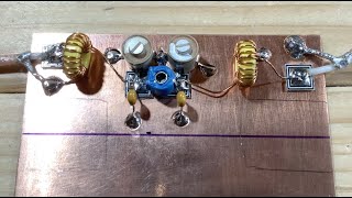
The SolderSmoke DCR challenge is going well. Our Discord server is bustling with activity and we are impressed that several intrepid homebrewers have already completed the receiver. So, we know that you can too! In this episode Dean, KK4DAS walks us through the design and construction of third of our four boards, the 40-meter band pass filter. The band pass filter ensures that the only signals that get through the receiver to the speaker are those that are in the 40-meter band. Dean also gives an update on the Challenge and discusses some recent improvements we've made to the circuits based on feedback from our builders.
Join the discussion - SolderSmoke Discord Server:
/ discord
Documentation on Hackaday:
hackaday.io/pr...
SolderSmoke UA-cam channel:
/ @soldersmoke
SolderSmoke blog DCR posts:
soldersmoke.bl...


Thanks for the very good video Dean.
Quick correction - the T-50 designation means the toroid is 0.5 inches outer diameter (I misspoke and said it was 50 mm - another reason for all of us just to go metric!)
Good job Dean. Very clean audio as well. Best!
great build and we are hoping to start building this in the next few weeks what is great is that my (12yo) son wants to build this with me, so we are currently sourcing parts fortunately I have most in the shack :)
I decided that I have too many receivers and transceivers to be building still more. But I thoroughly enjoy observing the process. Thank you.
Here's a description of how my club worked locally to do a similar sort of build-it project that may give others some useful ideas:
I worked with my local ham club to help 24 hams build their own QRP 40 m CW transceivers. We'd get together at the club station building on Saturdays and build segments of the circuitry, then explain the circuit segment to everyone. Then as they finished the soldering on a section of the circuit each person would bring theirs up to our test-bench and we would get each circuit working properly. We had 1 person walking around helping people with parts ID and soldering, another person at the white-board explaining to the group how the circuit worked, and a 3rd testing and ensuring that each circuit worked once built. The 3 of us switched around or doubled up as needed.
The plan from the start was for the club to place a group order to get a good discount and spare parts, and allow everyone young or old to get started, whether they had the cash up front or not, then to all work together to organize the parts and the build, and have enough tools and materials handy to get started. With 3 of us knowledgeable builders and repair techs committed to the Saturday project each week, and with a couple of other club members agreeing to cover for anyone who couldn't show up one Saturday we could guarantee that everyone would end up with a good working transceiver no matter how inexperienced they were at building or troubleshooting. That gave them all the confidence they needed to purchase and build the kits.
The plan worked well, and after 4 or 5 Saturdays everyone had learned component ID and soldering experience, a growing understanding of the components and what they did, how to use a multi-meter to measure components and circuit voltages, and an idea of how to test and troubleshoot their own rigs. By the time we finished, several of them were even customizing their rigs with additional switches, built-in battery pack, and even a built-in freq counter. We also gathered materials for everyone to build their own simple dipoles for 40 meters, and that gave those who were ahead of the rest something to work on. I highly recommend this process for groups who are in a position to do it.
We ended up with 1 kit that we gave for free to a youngster to build for his own rig, and another unit that I built in advance to identify possible kit documentation errors, or mechanical construction difficulties, or defective or mislabeled components and to use during the Saturday sessions to show what the proper signals looked like when we were troubleshooting. That then became a 40 meter QRP rig for the club to loan out, or to demonstrate QRP with at public service or educational events.
From our experience I learned that a larger group, all working in the same location was very helpful, as everyone could help or explain things to everyone else even when they were learning themselves. I also saw the importance of giving each person involved a guarantee that their unit would work properly when done. New people to the construction aspect of the hobby can be very unsure of themselves, so ensuring that their project would work just fine when they finished it really smoothed the process.
What you are doing here is about as close as you can get to what we did, without everyone being in the same town and gathering together to work on our rigs. Your videos and explanations are excellent, and watching them provides the necessary confidence people need in order to convince them to give it a shot. You're a good Elmer.
John, thanks for the nice note. Your club project sounds fantastic. We did something similar at Vienna Wireless Society, except it was during the pandemic and our weekly group sessions were on zoom. I enjoy building with a group and learn as much as I teach every time.
Wow, audio amp R14 change to 100 ohms is a revelation! Now total current of audio amp and VFO about 43 mA now vs. the old 81 mA! Who'd a thunk there was an error on the schematic, ha ha. Glad to see the correction! I finished the receiver a couple weeks ago, it works well but I sure wondered about the very high current drain from a 9 volt battery! (I use a variable voltage bench supply set to 9.0 volts for all my tests.) (I have not figured out how to use Discord yet.) Steve AA7U
Steve: Great -- we are interested in seeing your receiver. Please send a video to soldersmoke@yahoo.com 73 Bill Hi7/N2CQR
Thanks to you and Bill for your work on this project. Your documentation and videos are really helping me to learn. Rookie question: Can the windings on the toroids be twisted bifilar fashion ?
The problem I would see with that is the wire's are different lengths. Depending on how you did it. At least one end of the shorter winding, will be lost in amongst the larger winding.
Hi Dean, not sure if it's been discussed elsewhere yet but C12 looks to have its positive connected to the volume control whereas it should be connected to R18, the most positive DC part of the circuit. Cheers, Ian VK7IAN
You are correct - even when I fix it I miss something! I'll correct it on the Discord server and before I upload the PDF.
At about 11 minutes you say the toroid is 50 mm diameter, as does the schematic. I think that should be 0.500 inches or 12.7 mm. Thanks for the videos! I’ve got as far as winding the variable inductor.
Good catch! Another reason why we should all go metric.