HVACR: How A Refrigerator/Freezer Defrost Timer Works/Defrost Timer Troubleshooting/Sequence/Testing

Вставка
- Опубліковано 29 січ 2022
- HVACR: How A Refrigerator/Freezer Defrost Timer Works/Defrost Timer Troubleshooting/Sequence Of Operation(How To Check A Defrost Timer For A Refrigerator/Freezer) SUPCO PSA140100 DEFROST TIMER
Commercial refrigeration systems are essential to the preservation of vast amounts of food products, and/or pharmaceutical materials in research settings. Refrigeration failures, therefore, are costly in terms of lost product and business.
For that reason alone, every component must function precisely as designed. That includes defrost controls. Defrost controls prevent the build up of frost or ice from refrigeration system equipment and supporting component parts.
The heat output that makes the defrosting possible is provided by either an electric or hot gas defrost system. Defrosts can be programmed to occur automatically, or they can be performed manually. Key parameters to any defrost event are of course time, temperature, and/or pressure set points. The setpoints control the defrost initiation start time and termination end time. As the defrost heats the coil to remove ice, fans are on hold until the termination set point has been met.
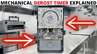
There are two types of defrost timers used in modern refrigerators -- constant, or continuous run timers, and accumulative timers. Constant or continuous run defrost timers run continuously as long as the refrigerator is plugged in. Accumulative defrost timers run only when the compressor is running. Accumulative defrost timers are also known as demand defrost.
Supco PSA14100 Troubleshooting/Wiring Diagram
Supco SA1650 Troubleshooting/Wiring Diagram
Supco PSK140100 Troubleshooting/Wiring Diagram
Supco PSG140100 Troubleshooting/Wiring Diagram
Supco PSD140100 Troubleshooting/Wiring Diagram
Supco PSA140300 Troubleshooting/Wiring Diagram - Наука та технологія


Thumbs up to you man, I wish you were my teacher. I've never had anyone explaining so clear and precisely like this. Pls help people like us with more videos to improve our skills.
Thank you Bongani! Really appreciate your comment 🙏 I'm glad you found this video helpful & I will continue to teach. I will be creating training courses so keep an eye out & subscribe for new videos every week!
Thank you very helpful, gracias
Excellent video. No loud music, flashing lights, just an explanation of how things work.
Terminal 1 is Hot not Neutral, as you can see, 1 feeds switches 2, 4, and the timer motor which is then connected to the neutral at the plug through terminal 3. Again, terminal 3 is NOT power, it is the neutral leg for the motor. If 3 were power, there wouldn't be enough voltage to power up the compressor, light, fans because there would be a voltage drop across the motor and resistor in the circuit. In a typical circuit, the neutral is never switched, only hot. "Common" in this scenario means that terminals 2, and 4 share a "common" power feed. Hope this helps. Otherwise, you're articulation is great!
You are right. 3 is common or neutral. 1 is live or phase. Proof is the diagram itself 1 splits to 4 & 2. Secondly, you can see the resistor is placed on the side of 4,2,1, which is the side current comes from. Resistor is not on the side of 3. The work of resistor is to control the current or simply minimize the current to protect the motor. 4 & 2 after being tested can be determined which is for cooling (compressor) & heating (defrosting). The longer time you turn till you hear the tick sound is for cooling. The shorter turn till you hear the tick sound is for heating. Every manufacture can differ numbers, but can be determined by diagram shown and/or continuity test. So do not cram the numbers.
Excellent! You are very clear, precise, and focused.
You were phenomenal on your explanation , a thousand thumbs up for you…one of the best videos I ever seen on repairing stuff.
Thank you very much 🙏 I appreciate the feedback. Stay tuned for new videos every week🔧⚡️
I am an electronic technician and your video explains everything very clear. Thank you!
That is awesome! You're very welcome & thank you! Stay tuned for new videos every week🔧⚡️
The best explanation I’ve ever seen about a defrost timer ! The best one by far !
Thank you very much! Stay tuned for new videos every week🔧⚡️
3 is common or neutral. 1 is live or phase. Proof is the diagram itself 1 splits to 4 & 2. Secondly, you can see the resistor is placed on the side of 4,2,1, which is the side current comes from. Resistor is not on the side of 3. The work of resistor is to control the current or simply minimize the current to protect the motor. 4 & 2 after being tested can be determined which is for cooling (compressor) & heating (defrosting). The longer time you turn till you hear the tick sound is for cooling. The shorter turn till you hear the tick sound is for heating. Every manufacture can differ numbers, but can be determined by diagram shown and/or continuity test. So do not cram the numbers.
Man this came on time. I was having trouble diagnosing one of these on a Hoshizaki IM this week. You explanation was excellent. Very easy to follow and understand.
Sir, you are a natural Teacher. Your tone, your patience and your manner of explaining a difficult issue is second to none. Bravo and thank you. I am now able to troubleshoot why my refrigerator freezer is cooling but my refrigerator is hot because my defrost timer is busted. You helped me Defrost it via manually engaging the timer while I waited 3 days for my new timer to arrive. Thank you again. God Bless You!
best video among many that i have watched. this video is well explained . so to check your timer with a multimeter just watch this video and do not watch anything else. hundreds of thumbs up to you man . thanks
3 is common or neutral. 1 is live or phase. Proof is the diagram itself 1 splits to 4 & 2. Secondly, you can see the resistor is placed on the side of 4,2,1, which is the side current comes from. Resistor is not on the side of 3. The work of resistor is to control the current or simply minimize the current to protect the motor. 4 & 2 after being tested can be determined which is for cooling (compressor) & heating (defrosting). The longer time you turn till you hear the tick sound is for cooling. The shorter turn till you hear the tick sound is for heating. Every manufacture can differ numbers, but can be determined by diagram shown and/or continuity test. So do not cram the numbers.
Exactly this guy he make people lost😅😅😅
Stop deceiving people, (M3) is Neutral (1) is common live terminal (4) is compressor (2) is defrost heater terminal.
Excellent informative video,this is as good as a community college electrical coarse. Great presentation!
Great video. Thanks for breaking it down to terms anyone can understand.
Clear and concise, amazing quality, keep up the good work!
Thank you! Stay tuned for new videos every week🔧⚡️
I have viewed many videos about the defrost timer.
I must say that your technique and general explanation of it is exceptionally good.
Thank you for your video. I was able to de the repair myself.
Keep making videos please.
Thank you for this detailed method of testing. Well done.
Excellent tutorial. I just went through a timer replacement but did not know how to trouble shoot. Now thanks to your tutorial I understand and am able to tet the failure. Thanks so much
I like the way you explain everything. Clearly..you're the best.
Well done!
You have a gift for presenting this material.
"Keep 'em coming." 👍
Excellent, and well-explained video. Thanks for sharing!!
Absolutely very clear explanation about a refrigerator electro mechanical defrost timer.
Thanks for the video bro.
Blessings.
tc.
Very educational. Thank you very much.
Thank you! Your Explanation is very clear to understand
You're very welcome & thank you! Appreciate the feedback🙏 Stay tuned for new videos every week🔧⚡ Stay safe out there
Hope everyone tells you that you are a great teacher !
very nicely and patiently done, thanks!!
Great job. It is super precise and clear to understand. Nice recap with the final review. Thanks.
Excellent presentation explains wiring and test points and what's physically happening. I'm a manufacturing engineer who had the good fortune to work with techs like you.
Thank you very much, you are the best teacher. 👍🤝
Great videos
This is for mostly commercial walking freezer or also residential fridges thanks!
Incredibly “simple” when explained as you do and seeing the internals.
Hard to believe how many things were outsourced to China for manufacturing. Crazy.
You are a great teacher! Very well illustrated
So clear. Credit to you. 👍🏼 From London
Thank you! Stay tuned for new videos every week🔧⚡️
Thank you ! Great instruction!
The only reason I sat through this video listening to you is because you sound young, calm, patient and a good teacher. I also think you are handsome.
God bless you and your parents.
I also like to thank the YT Algorithm for bringing me this video.
Haha thank you! I appreciate that very much. I think you have good intuition😎 God bless you too. I'm glad you found this video. Stay tuned for new videos every week! 🔧⚡️🙏🤙🙌
I have never shown my face here for years but I think at 100k subscribers, I will do a face reveal and let people know who I am🙃
Thanks for the Diagnosis of the Defrost Timer ⏲ Appreciate it 👏🙏
Good Job!! I have the same problem with my subzero 532 (30 yrs old). Contacts 1-3 were OL on my meter. I went through your process of manual bypass and it was exactly the same. I've replaced the timer and am waiting to see if my freezer begins cooling normally (upper 1/2 was warmer than bottom 1/2). I'm confident we fixed it (you and I ;--))
Thanks for a great video! Cheers from Sweden! 🇸🇪💪🏻🇺🇲
You're very welcome & thank you! Stay tuned for new videos every week🔧⚡️
This video was very helpful. Thanks for sharing and of course I'm going to share to my coworker:)
Exceptional vid! I am working on what may be the longest running unit in the WORLD here Its a Traulsen Digitraul Ref/Freezer URS48DT . It has the old (I mean REALLY old) defrost switch failing. The numbers dont match the Supco you have here and the wires are all diff colors pigtailed all over! I am going to now be able to match wires to function, with the new Supco. I am very thankful
Great electrical video, but these timers also fail mechanically when the motor gets old. The motor will stall and quit turning the wheel (Usually at a step position on the wheel) and this reeks havoc with Cooling operation. Then it will suddenly get its wind and start turning---maybe by someone slamming the refrigerator door at the right moment. It will cycle until the next impasse. The timer is bad and has to be replaced due to mechanical failure (Tired weak motor). Happened to me.
Thank you! Helped so much!
You're very welcome & thank you! Stay tuned for new videos every week🔧⚡️
Thanks my dear teacher, u are king of refrigeration so I hope to continue u explanation
Loved it! Thanks 🙏
Great! I appreciate your good way of explanation..
Thank you! Appreciate the feedback. Stay tuned for new videos every week🔧⚡️
studying for my hvac so its a good truobleshooting video
Thanks your vdo solved my Timer issue.
Thanks you so much. It was a big help!
Excellent explanation 👌 👏 👍
Thank you. I found this helpful.
Youre very welcome! Glad you found this video helpful! Stay tuned for new videos every week🔧⚡️
Great content thanks for sharing 😊
Great tutorial . Thank you
Thank you, this video is very lesson ❤
Excellent tutorial!!!!!!
good detailed explanation....i liked it....easy to understand....good work
Excellent video.
Anther great tutorial. Interesting and helpful video.
Thank you very much! Glad you found this video interesting & helpful. Stay tuned for new videos every week🔧⚡
Good job thank you for your help
Wow... Clear voice, clear explanation and clear video... Great man... Tq.
3 is common or neutral. 1 is live or phase. Proof is the diagram itself 1 splits to 4 & 2. Secondly, you can see the resistor is placed on the side of 4,2,1, which is the side current comes from. Resistor is not on the side of 3. The work of resistor is to control the current or simply minimize the current to protect the motor. 4 & 2 after being tested can be determined which is for cooling (compressor) & heating (defrosting). The longer time you turn till you hear the tick sound is for cooling. The shorter turn till you hear the tick sound is for heating. Every manufacture can differ numbers, but can be determined by diagram shown and/or continuity test. So do not cram the numbers.
Liked it, thumb up it, subscribed and saved it. Thanks man
Great video. A different YT video (that was also very good) said all the same except 1 and 3 were reversed. 1 was power and 3 was common. Now I wonder which is correct. Not that it matters! lol Per the wiring diagram, I think the other video is correct. I think 1 is power and 3 is common. Cheers!
Awesome Video....perfect!
Blessings and guidance thanks for your information it is a blessing.
excellent video, so clearly explained and well thought out. Subscribed, thanks.
Thank you very much! Appreciate the feedback & subscription. Stay tuned for new videos every week 🔧⚡️
3 is common or neutral. 1 is live or phase. Proof is the diagram itself 1 splits to 4 & 2. Secondly, you can see the resistor is placed on the side of 4,2,1, which is the side current comes from. Resistor is not on the side of 3. The work of resistor is to control the current or simply minimize the current to protect the motor. 4 & 2 after being tested can be determined which is for cooling (compressor) & heating (defrosting). The longer time you turn till you hear the tick sound is for cooling. The shorter turn till you hear the tick sound is for heating. Every manufacture can differ numbers, but can be determined by diagram shown and/or continuity test. So do not cram the numbers.
I really learn from this thanks
Pay attention to detail.Tip of the Day.
Always! Thanks for watching & stay tuned for new vids Kenneth! 🔧⚡️
This video was helpful. My experience with a Maytag refrig/freezer may help. My Maytag has two thermistors that send data in the form of resistance to the main board. As the temp gets lower inside the freezer or refrig, the impedance increases & that info is sent to the Maytag main board. At zero degrees F, Maytag wants my freezer thermistor to read 22.7k ohms but my thermistor read 16k ohms and the replacements I bought online were also incorrect. Because of the inaccurate thermistors, the defrost cycle never occurred. While replacing thermistors is easy, obtaining thermistors that match Maytag's spec was not easy so what I did was add a 6.8k ohm resistor in series with the existing thermistor. When zero degrees is achieved, the impedance is now 22.8k ohms and that's important because until the freezers achieves zero degrees F, the main board will NOT turn on the defroster. Instead, the compressor will run w/o stopping until the overload switch on the compressor opens the circuit allowing the suction line & evap to defreeze. I acknowledge that the additional resistor will skew the warmer temperature impedances, but that didn't make any difference and because the food compartment should never drop to zero degrees, I did not install a resistor in its circuit. Bottom line, my Maytag now defrosts every 18 hours for 25 minutes. I recommend installing a temp sensor in the freezer and in the food compartment that accumulate data and send that data to your computer in the form of a csv file so you can measure and track your progress.
Awesome vid
Great explanation.
Thank you brother! Stay tuned for new videos every week🔧⚡️
Very informative and educational
Thank you! Glad you found this video informative & helpful. Stay tuned for new videos every week🔧⚡️
Awesome 👌🏾
Thanks so much now I know what to do with my bad timer .... disconnect #3 so the timer does not advance out of cooling mode... then to defrost I need to manually advance the timer to the defrost, wait 20 minutes, and then advance it to cool again.... or find a new timer at a reasonable price and replace the bad one....
Love your channel
Thank you Alex! Stay tuned for new videos every week🔧⚡️
thanks for very calm explanation, new subs here...☺️
You're very welcome & thank you! Stay tuned for new videos every week🔧⚡️
great work bro
Thanks. Great video and explanation. My WR9X489 timer shares #3 with either #2 or #4 as cycle dictates, not #1, as in your video. Is #1 always neutral regardless? Is #3 always hot? Is #2 always heat? Is #4 always compressor? Regardless?
Great video I just ordered frost timer HOPE this fixes it, I get OL 3-1 you said its bad i got that correct i hope
$42 for new one
🇺🇸💪👍 great presentation and information
Thank you! Appreciate you Shine🙌🇺🇲 Stay tuned for new vids every week & stay safe out there 🔧⚡
Excellent in explaining the function of the defrost timer ! Is the motor build inside of the timer ?
very very good!
Neutral is always 3, the phase from the temperature thermostat comes to 1, then it goes to 2 when defrosting to the defrost thermostat, then to the terno diode and then to the heater.
Greetings and happy work.
Very interesting video.
Good explanation thankyou
Pin 1: The main input power is attached to pin 1.
Pin 2: When in defrost mode, the power (pin 1) connects to pin 2, which activates the defrost mode.
Pin 3: This is your ground / neutral wire. It will be separated from the other three pins.
Pin 4: When the timer is not in defrost mode, the power (pin 1) connects to pin 4, which activates the compressor and fan.
Very good information bro nice video keep it up God bless
Thank you! Stay tuned for new videos every week🔧⚡️
Thank you,
Great video! I do have one question. If I have 120v and everything is running via manually turning the dial, everything run, but not cool? Testing between 1 & 2, and 1&4 work. But no continuity between 1&3.
Cheap meter, you get what you pay for. try the same test with a fluke.
👍💪🇺🇸❄️ ? About supco universal electronic defrost timer. Looks like the one in video but it’s not mechanical. I’m getting ol between 1 n 3 . Is that because it’s not mechanical? I do have continuity between 2n 4. This was on all 3 timers . Ur thoughts?
I like your gloves it looks cool 😂
Very interesting
Thank you bro……
Nice tutorial
Thank you! Stay tuned for new videos every week🔧⚡️
Thanks.
Awesome.
Thank you! Stay tuned for new videos every week🔧⚡️
Do you have a video of the wires , if ,as in my case, someone took the wires off so i dont know which goes were ?
Good information ℹ️ video
Thank you! Appreciate the feedback. Stay tuned for new videos every week🔧⚡️
Best explanation on UA-cam so far !
Question: if I want bypass the 20 minutes defrost time ( to run and use minimum watts from power bank during power outage) then I should rotate the screw timer till click sound ?
no, you should cut the wire coming from the number two terminal and wire nut both ends.. When box temp. cannot be maintained, reconnect the wire. defrost heater uses 500 watts as opposed to cooling which uses about 150 watts. I would get bigger generator and keep my hands off unit.
JMT is the cream of the crop!
Haha thank you! Stay tuned for new videos every week🔧⚡️
I have a question I replaced both the defrost timer and the freezer thermostat it works sometimes but then it stop defrost could the heater be bad?
Just one question…when the timer is running does the blue tab that you used to advance it also go around by itself while it is operating?
Are the Sears/Kenmore defrost cycles typically DISABLED when the refrigerator door is open (as detected by the refrigerator inside light switch)?
Great video, great explanation, in what equipment do we find this type of defrost control?
Refrigerator