Automatic Water Level Controller for Submersible Pump and Overhead Tank | 555 Timer Projects 2021

Вставка
- Опубліковано 28 тра 2021
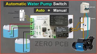
- In this mini electronics project, I have shown how to make an automatic water level controller for submersible pump and overhead tank with a 555 timer circuit. This automatic water pump controller also checks the water level of the underground tank, then starts the pump. And there is also an emergency stop switch to stop the water pump.
Here, I have used a 30A relay, so you can easily control up to 1 HP pump with this simple automatic pump controller.
Visit the following website to get electronics components, modules at a very reasonable price
utsource.net?source=UA-cam
[NEW] 555 ic Automatic Pump controller with Manual control: • Automatic Water Pump C...
[NEW] Fully Automatic Water Pump Controller using Arduino: • Automatic Water Level ...
I have shared the complete circuit diagram during the video.
I have covered the following topic in this DIY water level controller switch
00:08 How to use the Automatic Water Level Controller circuit
01:13 Required components for this 555 timer projects
01:39 Download the PCB Layout for the Water Pump Automatic Switch
01:52 How to make DIY PCB for automatic pump control
05:13 Connect all the water level sensing wires with PCB
05:48 Connect the PUMP and Supply for the PUMP
06:19 Testing the automatic water tank filling system with AC 220V bulb
Download the PCB Layout for the Automatic water pump controller from the following article
easyelectronicsproject.com/mi...
With this simple 555 timer circuit, we can stop the water overflow from the water tank. And the pump will automatically start if the water level becomes low. So we don't need to start and stop the pump manually.
Required components for the water pump automatic control circuit with Amazon Affiliate link
555 Timer IC (1no) amzn.to/3fsTH66
BC547 NPN Transistor (2no)
1k 0.25-watt Resistors (2no)
22k 0.25-watt Resistors (3no)
180k 0.25-watt Resistor (1no)
1M 0.25-watt Resistors (2no)
LED 1.5V 5-mm (1no)
1N4007 Diode (D1) (1no)
100nF (104) Capacitor (C1) (1no)
12V SPDT Relay (Contact Rating 30A) (1no) amzn.to/3uxyegL
Connectors & IC base (4 pin)
Slide switch (1P2T) (1no) amzn.to/3c4HnHb
Zero PCB or plastic sheet amzn.to/2SC091N
Please note down the following point before making the circuit.
1. Here, I have used 30A Relay, so you can easily control up to 1HP pump
2. For the 3ph pump, you can control the starter with this circuit.
3. Do not coil the water level sensing wires together, keep them separate.
4. The pump will automatically start for the following conditions
- Overhead tank water level comes below the "ON" level.
- Underground water level above UL1 level.
- Manual switch S1 should be in ON position.
5. The pump will automatically stop for the following conditions
- Overhead tank water level touches the "OFF" level.
- Underground water level comes below UL1 level.
6. If you use a DC pump, then connect the DC supply.
7. For the control circuit you have to give a 12V DC supply.
Please take proper safety precautions while working with the high voltage.
After watching the video, you can easily design this automatic water tank level controller motor driver circuit for your home.
If you face any issues please let me know in the comment section.
#waterpumpautocutswitch #555projects
-------------------------------------------------------
WARNING:
This video is for demonstration and educational purposes only.
Each demonstration presents risks and hazards that must be fully understood before attempting.
And should be performed only by professionals
------------------------------------------------------
Thanks For Watching...
✅ SUBSCRIBE ✅LIKE ✅SHARE ✅ COMMENTS
Website: easyelectronicsproject.com/
Facebook: / techstudycell
Instagram: / techstudycell
Telegram: t.me/techstudycell/
-------------------------------------------------------
Other useful videos:
How To Make Motion Sensor Light Switch using CD4017 & IR sensor
• How To Make Motion Sen...
IR Remote Control ON OFF Switch using 4017 IC & Relay
• How to make wireless I...
How to calculate resistor value for LEDs in a circuit for 9V and 12V
• How to select resistor...
How to make PWM DC Motor Speed Controller circuit using 555 Timer IC
• How to make PWM DC Mot... - Наука та технологія


Watch [NEW] video on Automatic Pump controller: ua-cam.com/video/bgARqosK7T4/v-deo.html
[NEW] Arduino-based Fully Automatic Water Pump Controller: ua-cam.com/video/qwSp1OE0VG4/v-deo.html
Well described... Thank you for sharing👍
Thank you very much about this new circuit I am always fallowing your best uploads.
Excellent idea to make pcb for projects at home. Very good.
Thanks for the feedback
Notwarking
What wire diameter do you recommend if the overhead tank is 70-75 feet from the circuitry?
I could calculate it if you can give an idea about how much current flows through those sensing wires(considering @ 12v)
Another thing, is a 100A solid state relay enough for 2hp motor?(to my calculation it has somewhere around 500w overhead)
@Tech StudyCell and if I want to supply 5v (Mobile Charger) instead of 12v and change Relay to 5v 30A 230VAC, will this circuit work without changing any other components? 5v is more convenient then adding another bulky adapter for 12v. Please explain.
Sir you are genius,
Your pcb making method is very good and easy to make,
Sir please make this type running led circuit diagram,
Running speed adjustable 10 led chaser with CD4017 and NE555 ic
wow excelent idea , lot of water pump project in a single project , that pcb is cool , Great work
Thanks
Excellent!
Hi. Good work. Can you please do semi automatic water pump controller. Automatic off when tank is full and manual on when water tank its get empty or when needed!
Great project 👍
Thanks
Bravo !
The best of circuits I watched ever on UA-cam. I'm not an electrician nor a circuit expert but the way you presented this video without commentary I will definitely try to make it by myself.
I have a suggestion though. You rightly have inserted dry run protection by setting a sensor in underground tank to ensure presence of water. My suggestion is to modify it instead of presence of water in underground to sensor beneath pipe which fills overhead tank with time elapse sensing.
It will ensure dual purpose of dry run protection. It is possibility of existing water in underground tank but for any reason whatsoever water may not be flowing in overhead tank. In a few seconds if anything is normal, water flows in overhead tank enable the circuit to run as normal otherwise it should be disconnected.
Hope you understand my layman's explanation and will try to modify this excellent circuit.
To my raw assessment, if I put two wires meant for underground tank on flow of overhead tank or in water supply pipe and a little delay may be produced by adding a capacitor.
You may provide an exact solution but my intention is to rely on water flow instead of presence of water in tank which is definitely 100% surety of dry run protection.
Thanks for the suggestion. Will try to add flow sensor in upcoming video.
@@TechStudyCell Dear would you like to send me new pcb design and lay out of components diagram. Regards Iqbal Islamabad Pakistan
Seu trabalho é show de bola, é da hora! Vi os dois, ambos são bons; este é big Show.
Thanks for good video. Can you make one with solar pannel and battery. If possible with a flow sensor so the motor can stop automaticaly.
I want to make so can you tell how much input max amp can be given to circuit 2amp 3,4 like that
Me gustaria ver el circuito para adaptarlo a mis necesidades. (I like to see de circuit), gracias(thank)
How long the sensors cable can travel? Is it work from ground floor to 10th floor?
very good video, My home has a very old pump it's totally rusted can't find out what hp it is , but from size of it its minimum 2 hp , what changes should I make in relay etc to suite my needs
very interesting,well explained,but show us the working circuit diagram of the model pl..
Hello sir, that was an informative video, Can we add up dry run in this
All d the best
Tanks 🎉❤
Great project! Can you modify the design in such a way that a momemtary swich activates a relay for 10sec. which then starts a pump. In this 10 sec. a waterflow sensor must be on and then keeps the relay activated. If the flow stops ( sensor off), the pump stops. Thanks.
Can we do this project with the help of breadboard
Okay I have a couple questions, what is the purpose of a common wire ? What does it do ? Second do the wires have to be in separate containers ? I am trying to modify/ find something that fits my need for my aquarium. I am trying to take water from my sump filter( under water tank) and make it go into the main tank (over head tank). I am trying to recreate tide changes in the aquarium so when the water gets to low the pump turns off and when it gets to high it turns on in the sump, that way it gives it the appearance of the tide going in and out. For my situation the on an off wires would have to be switched is that possible? The on wire would run dry during high tide be cause most of the water would be getting pumped out but once to much was pumped out it would trip the off wire causing the pump to turn off and letting water return into the sump and the cycle would repeat over and over , the UL 1 wire would be 2-4 inches below the off wire as an emergency shutoff so the pump would t run dry because water evaporates. Do you think it’s possible to do this ? Are there ways to protect the wires as I want to do this in a saltwater tank ? Can I attach float switches to the wires ?
Sir can you please give me a footprint of components that are used in pcb design
Excellent 👍👍
Thanks
👌👌👌👌
Bro make a wireless water level controller for contactor type submersible pump starter which has ON and OFF push buttons..needs two separate relays.. Use Arduino and nrf24 modules with display status
Very Nice.
Plz add Wireless Water Level Indicator with Buzzer for Low level & Full Tank alerts
Sir ur idea is good but for under ground u will need three wire sensors as the water touches ur ul 1 ur pump will sart and when water level goes below it it will stop so when a little water will fill th pump will start stop continuesly so u should make three wire sensor for under ground tank thank u
What type of engine do you use in this video to fill the water container?
CAN I USE BREAD BOARD INSTEAD OF THIS ARCRYC SHEET?
Brother if I use 9v DC attery on the circuit will that work with the 24v relay?
For same work
No. 24 v relay w 24 v Batts
Awesome project, is there also a way we can have a switch which works in night only when it detects motion... Please help
Okay. Noted
How many amps 12v dc supply I should use
Will it be easier by using one sided copper plates
How can I connect to submersible starter
Sir...great project...
Sir i used 5v relay...and input 5v...so..any changes in registor..value..?
How will that motor start automatically can i get a workinb principle
Can u make this project with waterlevel monitor using oled display ?
I have one doubt ...if i connect this circuit in my motor..... what is the maximum hours it can be run
Nice
👍
Sir..can I used 12v-24v submersible pump?
maximum How many amps can input load up to 12V.
♥️♥️♥️♥️♥️♥️♥️♥️♥️♥️♥️
greetings first of all, I must congratulate you for the circuit, I already have it mounted on a protoboar and it works as designed, but in my case I am going to use a well to fill the elevated tank so I see a difficulty and that is when the well sensor is out of the water the pump will stop and when the level rises a bit it will start again and so on, is there any way to avoid this? Greetings and thanks
How to add LED indicators for LOW & HIGH?
DC jack wire where it will be connected?
Can I use 10k ohm resistors in place of 22k ohm resistors
I have cross checked all joints & didn't find any problem but Still not getting power at output.
Kindly please reply 🙏🏻
And help in solving the problem
How long the wires can stay in water? Due to corrosion the wires will be damaged. Where we can use this?
Can u share the design and equations its required for project in collegw
Nice project and smartly presented....
Now plz reply.....
I want to keep ON waterpump, till sensor wire touches water....
When NO water touch to sensor wire, wait timer 5-7 or 10 minutes delay...
NO water touch during this delay ..... then Pump should OFF.
NO automatic ON is required....
The pump will be manually ON.
Purpose this alteration is for incoming water line...
to avoid idle run of pump on sudden stopage of water supply.
I hope you understand my requirements...
Hi Great project. how to add dry run sensor? pls make video.
Hi..Why cant we incorporate a 12v supply on the board itself instead of giving a separate power supply point for the 12v.
The circuit diagram should be modified for only 220v input with required components on board for automatic voltage reduction wherever required.
Very superb,,,,,I want circuit diagram pls
In 1st step The motor is working upto the high level and motor stops,then water level decreasing up to the low level, when it reaches below the low level motor stars but immediately it stops when water level touching the low level. Plz reply
Thank you for this very good video . I have a 12V pump. What kind of relay can I use ? Thank you very much
You can use the same relay, if the current rating under 30A. Give 12V input for both PUMP and control circuit
@@TechStudyCell thank you very much and keep on posting such videos !!!
Hello brother I want to use it for 220 v water pump .can i ?
Do you have pcb for this please
How to connect in float in this circuit
Where to download the PCB BOARD LAYOUT?
TOO FAST TO CATCH THE LOCATION.
TOO SNALL YO READ AND OUT IF FOCUS
OTHERWISE A GREAT PROJECT
I am new to Electronics , i would like to understand how to generate Garber file , which software ? Please reply ,
1m ka resistance ground se connect Kiya he agar wo resistance na lagaya to kya honga
Ya 1m ke jagah 2ra konsa resistance lagaya ja sakta he
This circuit used to borewell motor ??
bro please can you give the file of pcb cz i catn edit gerber file
Hello can I use 10A relay instead of 30A for a 5v submersible pump
Yes
@@TechStudyCell thank you
i tried the project and it worked
👍
Can we make it for real use....
My dear friend good evening every think so okay but what about component box it means complete set up box that should be metal body or fibre body you can design that also so that will be a helpful for everyone for me also thank you for kind information I am waiting for your next video
sirf roof tank ka dry run chahiye jisme 2minit pani nehi anese automatic motor band ho jayega or bazzar bajne lagega . fir use manually reset karne se auto kam karega. plz aisa circut banaye to bohut help hoga.🙏
Please make it for 3 phase motor.
It's looks nice, I want to make one,
Did any one tried doing it ? Please do reply
I made one w a simpler circuit
U must use an electrolyte in the water such as salt.
Sir are you selling the pcb
Practically when an open well submersible pump stops , the water filled in the pipe rushes back in the tank. As per your circuit the pump will start again and stop below the sensor, ultimately your relay will burn.
I manufacture water level controllers with flow sensors too. This is my advice, you can experience it also.
The pump will not start again until the water level touch the middle wire.
@@TechStudyCell absolutely right but when the pump stops the water filled in the pipeline to the out let of the pump rushes back in the tank and the cut off sensor again becomes active which ultimately starts the pump. This oscillation creats lot of sparking in the relay . That's why professionals always use 3 sensors like in the over head tank. I hope you will visit and see your self the operation of an open well submersible pump working. Your circuit will be good for open air self priming pumps. only.
Please make wireless water level controller circuit.
can you make an arduino version?
Motor are not stooping even if touching top sensor...it continues running from switch start
It is use Ac motor?
Nice project
Thanks
@@TechStudyCell hi, should we remove printed paper after done are can we keep it.
Sir PCB layout download nhi ho rha
What purpose the 12v is in that circuit
Echo devices is mandatory for this project
Is there any code for this project?
Nice project...but can you explain this project..this will be more helpful
Thanks Subhajit for the share, can you please help with a circuit design i.e. use a 30 Amp relay (5V/12V), with add Nodemcu and Ultrasonic sensor to activate relay during specific time and the logic to have dry run protection, Example: if water level % in sensor does not increase in 5 mins the relay shall stop the motor.. i will contact via email, please check.. Thanks again
Really thank you bro. Working well.
But , my wire getting rust every time. Any solution?
Hey nibin, can u just help me rectify my circuit as it is not functioning properly.
Not working
Hello
Can you make tutorials about the new version of blynk app and how to use the new features please ?
Okay
@@TechStudyCell thanks bro 👍
음 이건 복잡한 회로나 부품 필요 없고 릴레이 2개와 워터펌프 그리고 전선만 있으면 작동을 시킬수 있습니다.
만일 감전사고 같은 안전을 위해 5V 아답터와 5V용 릴레이가 필요합니다.
그러니까 5V용 아답터와 5V용 릴레이 그리고 220V용 릴레이와 워터펌프만 있으면 나머지는 전선 연결만으로 물탱크에 물이 필요한 만큼 차면 펌프가 꺼지고 또 어느 부분 만큼 비워지면 다시 펌프가 작동되는 시스템을 만들수 있습니다.
물탱크의 센서는 영상에서 나오는 3종류의 전선을 사용합니다.
맨 밑바닥 접지용선을 A라고 하고 물이 떨어지는 순간을 감지하는 선을 B라 하고 마지막으로 물이 원하는 수준으로 찼다는 것을 감지하는 선을 C라고 하면
조건은 다음과 같습니다.‘
A와 B선이 끊어지면 워터펌프 모터를 작동시킨다.
A와 C선이 이어지면 워터펌프 모터를 중지시킨다 입니다.
이를 위해선 릴레이 2개가 필요하지요.
하나는 물탱크에 5V용 릴레이를 작동 시킬 5V 센서용 전기선을 넣어 5V용 릴레이가 꺼지면 그것으로 220V용 릴레이를 작동되게 만들어 워터펌프를 가동하면 됩니다.
물론 워터펌프가 용량이 적은 것이면 5V용 릴레이 하나만으로 220V용 워터펌프를 작동 시킬수도 있습니다.
워터펌프 용량이 킬로와트 단위로 크면 릴레이 2개가 필요하지요.
아니면 220V용은 릴레이보다 용량이 큰 전기를 이용해서 전원을 ON/OFF 시키는 자동 차단기를 이용하면 됩니다.
My IC 555 is getting burn every time
?
Why this happen..
Plz replay
same for me, what to do
make this for AC 240V 2 HP motor for home
Onde está o esquema???????
IC Heat ho raha hai toh kya kare
Hello I want to make it for 2 hp motor what do I need to change
no. but pls take proper safety precaution, first test the circuit, then connect motor. check disclaimer
@@TechStudyCell matlb kar sakta hun...
Circuit website address?????
The switch and LEDIS BETTER IF MOUNTED ON A SURFACE. OF THE PROJECT CASE.
Can I use 1hp ac water moter pump
Yes
What about 1.5 hp?? Can i use it on 1.5 hp motor
Hello and HELP : I’d like to build your fantastic project ..! Were can I get the PRINTED CIRCUIT BOATD..! Can you help me obtain 2, I’m 78 yrs old and not that good at soldering ( not a steady hand).. can you send me to a LINK, were I can buy one .? I REALLY WANT THE PROJECT FOR WATERING MY PATIO FLOWERS ..! I have two containers, and your circuit would work PREFECT…!
Old man Jim
Sir pump have 2&3 hp then which components change
Only the relay
@@TechStudyCell and if I want to supply 5v (Mobile Charger) instead of 12v and change Relay to 5v 30A 230VAC, will this circuit work without changing any other components? 5v is more convenient then adding another bulky adapter for 12v. Please explain.
5 HP motor hoga to kya karna padega??
complete circuit 5pcs need
how you get those all components?
You can get it from Amazon. Link given in description