Exploring the ECU hardware and testing - Part 3 (fault finding example with IGF signal simulation)

Вставка
- Опубліковано 1 жов 2024
- Exploring the ECU hardware and testing - Part 3 (fault finding example with IGF signal simulation)
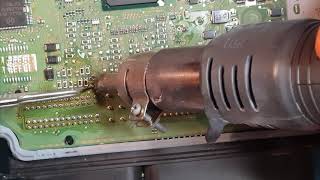
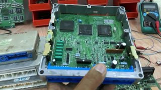
This video explains the ECU circuit board and demonstrates the way of crank and cam signal simulation to run the ECU and perform the different testing.
The engine ECU controls the injection of the fuel to the engine and the timing of the spark to ignite it. It determines the position of the rotation using a Crankshaft Position Sensor so that the injectors and ignition system are activated at precisely the correct time. It uses also number of sensor to read the status of the engine in order to run the engine at optimum performance.
The input to the ECU includes the following sensors:
Crank Position Sensor
Cam Position Sensor
Knock Sensor
Engine Coolant Temperature Sensor
Manifold Absolute Pressure or MAP Sensor
Mass Air Flow or MAF Sensor
Oxygen/O2/Lambda Sensor
Fuel Pressure Sensor
Engine Speed Sensor
Throttle Position Sensor
The output from the ECU includes the following devices:
Injectors
Throttle body control
Ignition coil
Load relay output
Malfunction lamp
Fuel pump
Idle control