Electric Motor Bridge Amplifier Explained

Вставка
- Опубліковано 24 сер 2024
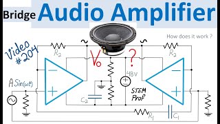
- Motor Driver Circuit Design with Bridge Amplifier is explained and analyzed in this video. How does the bridge-connected motor driver work? What is the output voltage or motor driver voltage as a function of input voltage? What are the proper choices for Op Amp and high-current buffer? These questions are answered in this video. This motor driver circuit effectively realizes a single-input to differential-output amplifier that is designed with two operational amplifiers and two high-current buffers that are wired to form a generalized non-inverting amplifier on one side and a generalized inverting amplifier on the other side of the motor with high-current buffer in the negative feedback loop of the amplifier. This design allows to use a low-current op amp. The differential output voltage doubles the motor drive voltage. A combination of Kirchhoff Circuit laws KCL, KVL and op amp virtual short are used to analyze this circuit and to find the formula for the output voltage. Examples of proper choices for circuit components are discussed including the Texas Instrument's dual-channel OPA2810 op amp and LMH6321 high speed buffer with adjustable current up to 300mA. More analog circuit videos are available in the • Physics and Mechanics ... Analog Video Playlist.


Motor Driver Circuit Design with Bridge Amplifier is explained and analyzed in this video. More Amplifier examples are listed below: PID Controller for Servo Motor explained ua-cam.com/video/NATBlfABXrA/v-deo.html
Electric Circuit Analogy for Mechanical System: ua-cam.com/video/997hfjGK3_w/v-deo.html
Strain Gauge Wheatstone Bridge Instrumentation Amplifier Explained ua-cam.com/video/io1yBcCsP-Y/v-deo.html
Push-Pull Power Amplifier ua-cam.com/video/866MYibo8yE/v-deo.html ,
Flex Voltage Regulator Example: ua-cam.com/video/CJl-urzeiTo/v-deo.html
Amplifier with -25 to 55 dB Attenuation-Gain range ua-cam.com/video/oyz6lTGd2Xo/v-deo.html
Instrumentation Amplifier with Electronic Gain Control ua-cam.com/video/C4tghZ-q6Zs/v-deo.html
More Analog Circuit Videos are listed in the Analog playlist: ua-cam.com/play/PLrwXF7N522y4c7c-8KBjrwd7IyaZfWxyt.html I hope these Circuit design and analysis videos are interesting. 🙂
That circuit would make a lot more sense as an automotive audio amplifier to get 4X the power without needing specialty low-Z speakers and thicker wiring than it does for driving motors of any meaningful power. Driving motors is better left to PWM drivers... single H-bridge driver for reversible DC motor, double-H for steppers, 3ph bridge for most others.
Thanks for sharing your insights & good suggestions. This Bridge Amplifier works well for lower current motors as described at 1:40. For higher current motors we can use power Transistors at the output of Buffer. And to your point ua-cam.com/video/EDpu6urAtHA/v-deo.html video is about op amp based Bridge Audio Amplifier. 🙂
@@STEMprof What DC motor size would you drive with an analog amplifier? I wouldn't drive anything much over a cell phone vibrator motor with that - low duty cycle sub-1W loads with minimal impact on power draw. For anything much beyond that, the heatsinks you will need for your analog driver will greatly exceed the cost of a D-class amplifier.
Putting a totem pole on the opamp output for increased output current/power may help for driving larger loads but doesn't help with efficiency.
@@teardowndan5364 well said and valid point regarding efficiency. Thank you!
Very good video, how does one even design this 😂? Nice overall.
You are welcome. Glad that you liked this video. Here is an application of this circuit ua-cam.com/video/NATBlfABXrA/v-deo.html as power driver in PID Controller for Servo Motor. I hope this video is interesting as well. 🙂
Why not configure the buffer amps directly as BTL and ditch the first stage?
That's a great question. Reason is that when high-current Buffer is connected inside the feedback loop of the more accurate (low-drift) precision Op Amp, the offset voltage of the Buffer and other errors are corrected by the open-loop gain and feedback of the op amp. I hope this is helpful.
@@STEMprof I see your point about the feedback loop compensating for inaccuracies inherent in the buffer. So if one is willing to sacrifice some precision, then I think my suggestion could still apply. Thank you.
You are welcome. Yes, if error and its potential accumulation over time are negligible. Otherwise the Buffer in the loop of cheap low-drift amplifier is recommended. Thanks again for the good question. 👍
I'm not sure i quite understand why the low current amplifier is needed. Couldn't you directly connect the input voltage to the high current output amplifiers?
@christopherventer6391 Reason is, when high-current Buffer is connected inside the feedback loop of the more accurate (low-drift) precision Op Amp, the relatively large offset voltage of the high-current Buffer and other errors are corrected by the open-loop gain and feedback of the low-current low-drift Op Amp. An application of this circuit is in ua-cam.com/video/NATBlfABXrA/v-deo.html as power driver in PID Controller for Servo Motor. I hope this explanation is helpful.
@@STEMprof Ah, ok. That makes sense!
Are you sure that an Opamp can drive a motor??
Most likely people use MosFETs
That's a good question. And the answer is yes as mentioned at 1:40 minute depending on target applications. In this case the target was up to 300mA and hence the proposed Texas Instruments LMH6321 high speed buffer is good enough. For higher current applications, higher power buffers or addition of power transistors might be needed. I hope this is helpful.
@@STEMprof it would be better to add a mosfet between the OPAMP and the motor for safety
@ahmedmoustafa6829 Good point. For higher current drive application power transistor is surely needed. Thank you!