I love that you use the 741 here. This clears up a lot of questions about dual supply requirements for the 741 (and others)! Thanks for moving slowly and deliberately for us beginners. I also learned a few new things about viewing signals on Oscopes in this tutorial. Thanks for making this!
I have been watching various opamp videos over the last week or 2. this is by far the best demonstration and delivery of Info on this subject I've found yet. You answered many questions I still had with both on paper and physical examples. Lemme see what else you've posted!
This is an 'old' video. But a very important one! Many people, including yours truly, blindly use an op-amp and then wondering why it is damaged or why sellers con us, we then buy some more and same story, we buy even more and same story. Lots of wondering and blaming.
@@stevegoodjob5902 To put it simply, many people using an operational amplifier or transistor without understanding how it works. This is what I mean and is the problem. Problem is the human and not the operational amplifier or transistor. For instance, many people wonder why audio or signal clips or looks weird. The first thing they do is keep changing and buying different op-amp or transistor to test. They do that until a period of time they get fed up and start to blame the maker of op-amp or transistor. How is it possible that all transistors of all makers fail all together with 99.999999% rate of coincidence?!?!??!?!?! For some weird reasons they are not bothered to change other components and try different levels of power/voltage/current. They are somehow braindead. Doing the same thing expecting different results. You would be surprised the sheer amount of people having an oscilloscope still wonder why a circuit does not work as expected, and play the blame game. Any fools can own an oscilloscope these days anyway. As if having a digital clock and wondering how come it does not have the good old hands moving, that clock must be faulty, buy another digital clock and wonder why again no moving hand, must be another defective clock, buy some more, wonder some more, rinse and repeat.
Thanks Alan - like many others I refer back to your tutorials often. You balance theory and practical perfectly every time. One thing to note here is that rail-to-rail op amps are expensive! Order of magnitude up on the likes of an LM358.
I've been watching your videos for years, and it just hit me that your notes are actually analog Power Points!!! Thanks for all the theory. Very useful stuff!!
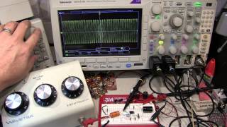
Man, having the horizontal lines there makes this crystal clear for me. Always been kind of fuzzy when playing with this on my own scope. I’ll have to make sure to draw those in. Nice trick 👍
BTW. Do not go too much beyond power supply range with your input. The AD8032 does support going about 200mV below (above) negative (positive) supply safely, and still maintain linearity of output vs input (obviously you would use gain less than 1 in this case usually). Above that the linearity (and distortion characteristics) can't be guaranteed. Additionally, 500mV is stated as a absolute maximum, beyond which opamp can be permanently be damaged. It is recommended to add external clamping diodes if you expect this to be possibly happening.
This did answer some questions! Questions that I didn't think of asking! Do you _teach_ the subject? Because you seem to know possible questions students will ask. Thank you very much for this video!
I have to thank you for your efforts to explain many interesting things in electronics. I have weak knowledge in this field. This video help me better understand about op amps things.
2nd time watching in as many days. Great videos! Having graduated in '88 with a BEET degree. I decided to try out these new fangled single supply op amps i.e LM358 lol.... After some frustration and thinking they somehow magically used a single supply your video set me straight. Doh!
Great delivery and information. I appreciate your ability to share the knowledge you have in a logical, easy to understand manner. Keep up the great work. By the way, I decided to subscribe. Thank you.
Super useful. Are there some performance tradeoffs to the rail-to-rail opams? Noise, bandwidth, input voltage offset, temperature stability, drive/sink output current, etc.
#2 view. Great work W2AEW. This is better instruction than at our local community college. My neighbor is taking electronics classes there and I shared your videos with him. He is impressed.
older amplifiers used transformer less power transformers, it was called hot chassis which didn't use an AC power transformer but a series of tube filaments to step down the AC voltage. I'm not sure how tube filaments step down an AC voltage, but many you might know. On the schematics it looks like 4 to 6 filaments stepping down 120VAC to 40VAC for the rectifier tube.
The schematic on the last page of my notes is accurate. In my case, the signal generator features a floating output (the shell of the BNC isn't grounded), so I was able to put it in series with the supply that I used to adjust the offset.
Thanks for the great information. I was, however, hoping to learn a bit about how to calculate the power consumption of the op-amp. So.. if the output feeds say an ADC, how do we calculate the power loss through the gain resistors and the chip itself. Once again, great tutorial. Thanks.
12:50 "And you plug it in, ... boom ..." Boom??? Reallly??? :-) But in general, there is a (small) perturbation near their zero, though. Good, very good, video. Second point, if the op amp has its offset not defined as being the earth ground we have to adjust the + and - signal with respect to the same zero origine... which can then be THE real headhake. I really hope everything is fine on your side, it is 2021 here!
Well done! What is the most effective method to bias the op amp using single power supply? Would it be split resistive or using other means? Thank you for your great to the point presentation!
I have tried measuring the AC line noise on the primary side of various equipment on an oscilloscope but not sure how do it correctly. How can you measure the AC line noise level using an oscilloscope or is it better to use a spectrum analyzer to measure AC line noise? my Fluke DMM meter can't measure the AC line noise level so what meter would do this?
At around the 2 minute mark, I don't think that point should be called virtual ground, unless it's a term that is used pretty loosely. Virtual ground for the op-amp would be there when you have the positive terminal connected to GND and negative feedback configuration, where the feedback action is trying to make the voltage at the negative op-amp input equal to the voltage at the positive input. In the circuit shown at the 2 minute mark, it looks like an open loop.
Great op amp video! I'm wondering how did you probe the signal generator input in ch 3? Where did you connect the ground clip at @8:00? Did you connect it to the ground (-) of the DC offset at non-inverting input OR at the node after it (+)? I feel like if I would connect it to the (+) node (or just before the 2.2k resistor) I would then short out the DC offset voltage because the other two oscilloscope channels ground clips are connected to the circuit ground.
@@w2aew Thanks for the response sir. I have actually sent a pm about the same on eevblog :D got really anxious about this ground loops ever since i have watched Dave's video on blowing oscilloscope probes.
What is the purpose of the 2.2k resistor at 7:30? I’ve seen these before, or even in the feedback loop of unity gain buffers, but never understood what they’re for?
I have a 741 op amp with a 170mV, 852Hz input sine wave, +5/-5V power. I have a 10k resistor from the inverting terminal to ground and a 20k feedback resistor (output to inverting terminal), the input is on the non-inverting terminal ... the gain should be 3... but instead the gain is roughly 1. (So the output is roughly 170mV.) The output is not clipping... I'm not sure what's going on...?
So if you are using the non inverting input as a voltage sensing/ smith trigger comparator mode is it still possible to use that input as a midpoint for split supply. Im using lm358 as a compartor to turn of a constant current load when a low voltage is sensed on the non inverting input. But the Op Amp output would not turn completly off it would stay 0.8 volts above ground, the solution may be to supply it with negative voltage to swing it negetive on the output. Il give it a shot, any input of some electro wizard appriciated
Great video, very easy to understand, I am building an audio signal generator and you can use eiher 6 volt sprit or 12 volt single, can you tell me which way to go? Thank you kindly!!
From a circuit performance standpoint, they'll be identical. So, it really comes down to details of your requirements. Do you want the output to be centered around ground and DC coupled? If so, then use a split supply.
What are the advantages of using Two Diode Full wave rectification compared to using 4 diode bridge full wave rectification? The Two Diode Full wave rectification has benefits how so
What formula can you use to convert Full wave AC voltage to the Equivalent Half Wave AC voltage and vise versa? Because if a circuit needs 26vac Half wave voltage, how can you convert this to the equivalent Full wave AC voltage?
at timeline 1:58 I had the op amp set up similar to that timeline setup with the - input floating. Even though I had about half the supply rail on the + input, the output voltage still remained at zero volts instead of climbing close to rail voltage. Not until i grounded the - input did the output pin voltage swing to 1.5 volt below rail voltage. So does this mean that both inputs of the op amp needs to be connected to the circuit for the op amp to work properly?
Yes, both inputs to an opamp have to be connected to something in order to work. At 1:58, this is just showing the bias setup for the non-inverting input, and the actual signal would be applied to the inverting input, which is not shown in this part of the video.
But electronic engineers and technicians say that the laminations changes the frequency response of the transformer is this true or false? or do they mean the core material inductance will change value because of the wire winding lamination?
Thank you so much or this excellent video which clear out some confusion on the rail to rail and split supplies concepts. I can't wait to see more OP-AMP tutorials (if you have more coming).
Around 1:50 you mention you AC couple the bias to ground "to keep it stable" can you point me in the direction of where I can get some additional information on that? I'm going to guess you mean the capacitor will keep the voltage "less spikey" and closer to a flat line? If that is the case I'd think you'd have to carefully select the cap so it let low frequencies pass but not high ones?
thannks for that video :) for my TDA2050 wich one is better to use for best result single of split supply?? CIRCUIT DESCRIPTION SINGLE SUPPLY VERSION The IC will work from 18v to 45v although performance and quality will be affected at lower voltages. If a higher supply voltage is used be sure to upgrade all the capacitor voltages. C5 must be at least 35v and preferably 50v or more. This will result in a large capacitor but there is room for it on the PCB. SPLIT SUPPLY VERSION This version uses a split supply, +/-12v instead of 24v. The supply can go up to +/-22.5v. The split supply version has similar performance to the single supply version. Vsupply = +/-18v, THD = 0.5% 18W into 8 ohms 28W into 4 ohms Vsupply = +/- 18v, THD = 10% 22W into 8 ohms 35W into 4 ohms Vsupply = +/- 22v, RL=8 ohms 25W @ 0.5% THD 32W @ 10% THD thedjfreeman08@gmail.com
I've never designed with this device. However, since the characteristics curves in the datasheet were all done using a split supply, I would assume the best performance is in that configuration. Probably a good question for the application engineers at ST.
w2aew for me i think for single supply they used a single ground thats commun for speaker munus power and signal in minus and for split supply they separate the ground by creating a virtual one i see that for single if someproblem occure it will affect the player device such as pc or phone... what do u advice me to chose as supply methode as i will bridge 2 tda to get more power output thanks have nice day
My first thought would be to use a split supply, for the same reason. If there's a fault, you're less likely to damage something else. But, I am not an expert in audio PA design.
for a balanced signal input, where you have a floating differential signal going into the +/- terminals of the opamp, a split supply would be more necessary correct?
if your opamp circuit with a virtual ground connects to a another opamp that is using a single supply (ex 0-12V), in the gain loop of a non-inverting amplifier, would you connect the resistor to the 0V ground of to the virtual ground?
Hi there, I tried to set this up with a non-inverting configuration and a 741CN, but I'm guessing this is not possible because the feedback resistor going to virtual ground from the output will mess up split voltage source? Is it the case that the potential divider only works as a split voltage source if there are no components (across which the voltage drops) between the potential divider and the 741?
Hi, very instructive video. What is the role of the 2.2k resistor connected to the + input ? The one that has its value in parenthesis, it is seen in the drawing of your example circuit at around 8:00 . Sorry if that question was asked already.
A resistor is usually used in that location to help minimize offset due to the input bias current of the op amp inputs. The value is usually equal to the parallel combination of the resistors connected to the inverting input, so it *should* be approx 1.4kohms. I used 2.2k simply because it wasn't critical for the video topic, and it was laying around on the bench near the breadboard ;-)
Thanks for the explanation! As far as I understand, since the gain here was less than 1.5, I suppose even this resistor wasn't necessary because the error would have been very small. Nevertheless it is important to know about this stuff. I was able to find a bit more in-depth about this watching EEVblog #479.
My question is that you used a variable voltage source to make an offset on both the positive and negative inputs (schematic 7:55), thus your input signal that you want to amplify is floating relative to ground, what if the input signal is not floating? how can i make an offset on the input signal, can i use a voltage divider, what if the input signal source has a very large impedance, should i use a buffer before? thanks
could I use such a rail to rail op amp with real ground on the positive input instead of using a virtual ground to obtain "0"? all I want is to increase the input signal from 0-5 vdc to 0-12 vdc... Could I use a LT1490 op amp for this application? thank you for your video and hope you will reply soon...
You can use the LT1490, but not as you described. Set it up as a non-inverting amp. Use a power supply >=12V. The simplest configuration would be a feedback resistor (output to inverting input) of 27k, and 20k from inverting input to ground. Apply your 0-5V signal to the non-inverting input, and the output will swing approximately 0-12v.
Well, from my interpretation, what you're calling a "virtual ground" is just a voltage reference. You could also call it an "ac ground" because of the very small shunt impedance due to the capacitor. The actual virtual ground exists on the "-" input, not the "+".
In old tube amplifiers the 6vac heat voltage the transformer didn't have a center tap for the ground for the 6vac. To convert a non center tap transformer to a 6vac center tap you put two 100 ohm balanced resistors and tie them to a virtual ground which will be the tubes plate voltage. Most plate voltage are from 200vdc to 450vdc. Not sure why they would put the virtual ground to a DC potential connected to the plate voltage so that the 6vac heat voltage will have a virtual ground virtual center tap. Have you heard of this type of virtual ground?
I'm thinking of adding an Eq circuit on to my DIY 200w amp Hifi. On the lm833 the Vcm is +/-12 +/- 14 but the Absolute rating Vcc ~ Vee is 36V does this mean I can use 24v Dc power source to power two lm833 plus the 200w amp it came with or will it fry the added chips ?
The LM833 is a pretty low power part, it'll only draw what it needs from the supply, so no danger I. Frying them even though the same supply is also powering a 200W amplifier.
Great video. thank you very much. What happened to output swing voltage if the output current is increased? how to use opamp to drive a low impedance load?
It depends on the specific op amp. In general, the available voltage swing is reduced into low impedance loads. Some op amps can drive low impedance loads better than others. Often times a buffer designed for low-impedance loads (like a push-pull stage) is included in the feedback loop of an op amp to improve the low-impedance drive capability.
@@w2aew Acutally I used push pull or single transistor at the output stage of opamp; it works fine but not efficient. With single supply, the output voltage has the dc offset.
If my question was answered 9 years after the video was published the question would be out of what is indicated below: Suppose your using a little module using a lm358 IC that was purchased out of China and pre-assembled to serve as a Mic or transducer preamp as I expect to use mine. Suppose the module has four pins with one for input from a signal source, one for output of signal from the lm358 and two pins for power supply. Suppose you do as I did which is connect two 4 pack AA battery packs in series and supply power to the module with the free end of the one battery pack leading to Vcc and the other free end of the battery pack leading to what one might call Vee on the lm358. The question then is what would you use as ground or the 0 volt reference point for the input and output signal? I have used the Virtual Ground created by where the two battery packs are physically connected thus I suppose the signal swings between +6 volts and -6 volts & I have used what leads to what I have called Vee serve as the ground for the signal's input and output and see no difference on my scope under each scheme. Any comments on this, to me, puzzle would be greatly appreciated.
Assuming you module was designed to be a mic preamp, then the input is most certainly AC coupled, so the ground reference for the signal doesn't really matter - it could be either supply rail or the virtual ground because from an AC standpoint, they're all the same (all shorted together with capacitors.
Hi I'm trying to create a pwm signal by comparing a triangle wave with a Sine wave. I've tried with triangle signal that is +/- 5vp from an occillator aast 100khz and a 400hz Sine wave +/- 5vp but it doesnt work. I've tried the 741 and a tl081 opamp and a lm339n but no succes yet. any help?
CryB4Die It's difficult to say without seeing your schematics, but there are very common mistakes that people make. The first is that you have to make sure that you obey the input voltage range limits on the devices used. Since your input signals go from -5V to +5V, this means that the power supplies on your op amps MUST be at least 2-3V greater than this - like +/-8V or so, or more. The input signals generally can not go beyond the supply rails (except in specific cases where the devices are designed for it), and often the inputs must be kept several volts from the rails (except in the case of op amps with rail-rail inputs). Also, for the LM339 comparator, it uses an open collector output, so it MUST have a resistor connected between its output pin and the positive supply.
Why does the type of kind of lamination on output transformers windings/wire change the frequency response of the transformers output? The Lamination coating on the transformers windings and wire will change the frequency response, any reasons why?
Hi. Can i ask some questions to you. I am currently working with Multiple feedback bandpass filter. And my circuit didnt work every time i tested it. I used lm324 op amp ic. Can you help me what is the possible solution for this or it might be the op amp ic i am using?. Can you suggest better ic for my application?. Tnx a lot
A LM324 should work in this application if the circuit is designed correctly. However, it is impossible to help without seeing your schematic, or knowing the details of the application (bandwidth, signal levels, power supplies available, etc.).
Tnx for the reply . I want to pass the band of freq from 400 to 1800 Hz. I choosed 1kHz as my center frequency and a Q of 20. I used 5V dc single supply. I connected my circuit components in a breadboard... And i am using microphone and audio jack as my input from sound. I observed the output in oscilloscope. And the output is only noise. the values of components are Rf=1.5M Cf=680nf R1=4.7k R2=12 and C1=2.2nf
Hi, we can make an offset on the positive input simply using a resistor divider, but how can we offset the negative input which takes the input signal without using an additional power supply? thanks
Hi! In your other video about Crossover Distortion you avoid it with a load resistor on the output while here, without any such load, you haven't any distortion despite the 5kHz frequency! How is that possible?
The LM1458 op amp has a different output stage compared to the LM358 that was used in the crossover distortion video. The LM1458 output won't swing near the lower supply rail.
Thanks for your answer. I switch to a NE5532N from Phillips and now I got no distortion at all, however I got 7mA of current instead of less than 1mA on the LM358, interesting... By the way, this chip has not the "slew rate" issue!
It is a very nice video. I have a quick question. Considering a comparator configuration, will it work with a single supply(12 volts) if voltage to non inverting input is in the range of mV and the inverting input is connected directly to physical ground( so that ground is considered as reference) ?
***** Isn't usually ground a part of the common mode range. Because In datasheets I have seen that the common mode range value varies within 2V of the supply rails.
palaprab Again, this will depend on the device used. Your scenario was described as single supply, so the assumption is that ground is the lower supply rail. Thus, you need a device whose input common mode range includes ground (the negative supply). Not all devices do this, so you have to specifically look for this. Those devices that specify the input common mode range to within 2V of the supply rail would not be suitable.
Can you make a video lesson about measuring power supply rejection ratio and also power supply control loop stability? They make special probes called power rail voltage probe, which i have never used one and don't know how its so much different
I'll add that topic to my list. Power Rail probes are special, wide-bandwidth, low-attenuation probes that allow you to dial-out the supply rail voltage, and concentrate the high sensitivity measurement (maybe 1-2mV/div) around the supply rail (large DC offset).
@@w2aew Back in the 60's and before they used "bootleg grounding schemes" because it was just a 2 prong Floating Earth and not using a 3 prong with an earth ground. When a piece of equipment is wired as "bootleg grounding using a 3 prong cable" ( Not 2 prong ) the DVM meter will be connected to earth ground or circuit ground. When making In-circuit voltage measurements all the voltage measurements are going to be incorrect and wrong because the equipment is wired as bootleg grounding? because when you disconnect the earth ground wire/bootleg ground the in-circuit voltage measurements on the DVM meter are going to be correctly different, any reasons why?
yes true, I just didn't know that different tube filaments has different resistance values which is a voltage drop. I thought as tube filaments all had the same resistance value.
Hi, I have some questions relating to thermocouple voltage amplification. The K type thermocouple output is DC but very low voltage. Do I need to bias the positive input of the op amp above the voltage range of the thermocouples output or can I just tie it to ground? Is it better to have an inverting or non-inverting set-up? I have some TL072/082 op-amps and waiting for some LM358's in the mail. The 358 datasheet mentions single supply voltage, the 072 doesn't, would the 358 be a better candidate? Thanks www.ti.com/lit/ds/symlink/lm158-n.pdf www.ti.com/lit/ds/symlink/tl074.pdf


I love that you use the 741 here. This clears up a lot of questions about dual supply requirements for the 741 (and others)! Thanks for moving slowly and deliberately for us beginners. I also learned a few new things about viewing signals on Oscopes in this tutorial. Thanks for making this!
I have been watching various opamp videos over the last week or 2. this is by far the best demonstration and delivery of Info on this subject I've found yet. You answered many questions I still had with both on paper and physical examples. Lemme see what else you've posted!
This is an 'old' video. But a very important one!
Many people, including yours truly, blindly use an op-amp and then wondering why it is damaged or why sellers con us, we then buy some more and same story, we buy even more and same story. Lots of wondering and blaming.
What do you mean? Where is the problem?
@@stevegoodjob5902 To put it simply, many people using an operational amplifier or transistor without understanding how it works. This is what I mean and is the problem.
Problem is the human and not the operational amplifier or transistor.
For instance, many people wonder why audio or signal clips or looks weird. The first thing they do is keep changing and buying different op-amp or transistor to test. They do that until a period of time they get fed up and start to blame the maker of op-amp or transistor. How is it possible that all transistors of all makers fail all together with 99.999999% rate of coincidence?!?!??!?!?!
For some weird reasons they are not bothered to change other components and try different levels of power/voltage/current. They are somehow braindead. Doing the same thing expecting different results.
You would be surprised the sheer amount of people having an oscilloscope still wonder why a circuit does not work as expected, and play the blame game. Any fools can own an oscilloscope these days anyway. As if having a digital clock and wondering how come it does not have the good old hands moving, that clock must be faulty, buy another digital clock and wonder why again no moving hand, must be another defective clock, buy some more, wonder some more, rinse and repeat.
Still useful information in year 2019. That's 6 years after publishing! Some things don't change.
Thank you! Finally someone who can explain the difference for connecting split and single power supplies to beginners.
binge watching all the circuit tutorials, trying to remember to like and comment on each as well
Really great tutorial. Clear and simple diagrams with a delivery style that I found very easy to follow.
Oscilloscopes are so cool! I just got a cheap one, but it is so fun to play with!
Flawless presentation and demonstration of material. Thank you.
Thanks to you I finally understood why my 741 is behaving in such a weird way, liked and subscribed
Wow, this could have save me a lot of pain back when I was figuring out the limits of a 741 the hard way.
Very well explaind. Doing and showing works better then text books.
I really like the way you explain. You always go the right level of the viewers. Thank you very much for all your effort and time. Good bless you
Thanks Alan - like many others I refer back to your tutorials often. You balance theory and practical perfectly every time.
One thing to note here is that rail-to-rail op amps are expensive! Order of magnitude up on the likes of an LM358.
Keep looking. There are many inexpensive rail-rail op amps out there. The Microchip MCP6001 can be found for less than $0.25
@@w2aew Cheers Alan! Thanks for the heads-up.
This is much better than using a powerpoint :D
Just a man, his pen, and some graphing paper.
I've been watching your videos for years, and it just hit me that your notes are actually analog Power Points!!! Thanks for all the theory. Very useful stuff!!
2022 watcher. thanks for this! helps a lot when u dont have split supply
Man, having the horizontal lines there makes this crystal clear for me. Always been kind of fuzzy when playing with this on my own scope. I’ll have to make sure to draw those in. Nice trick 👍
Your videos are really instructive.
I decide to watch 2 vids of yours every day from now on.
BTW. Do not go too much beyond power supply range with your input. The AD8032 does support going about 200mV below (above) negative (positive) supply safely, and still maintain linearity of output vs input (obviously you would use gain less than 1 in this case usually). Above that the linearity (and distortion characteristics) can't be guaranteed. Additionally, 500mV is stated as a absolute maximum, beyond which opamp can be permanently be damaged. It is recommended to add external clamping diodes if you expect this to be possibly happening.
This did answer some questions! Questions that I didn't think of asking!
Do you _teach_ the subject?
Because you seem to know possible questions students will ask.
Thank you very much for this video!
Nope - I am not a teacher - I'm just familiar with the common questions that people might ask.
I have to thank you for your efforts to explain many interesting things in electronics. I have weak knowledge in this field. This video help me better understand about op amps things.
Man, best teacher on youtube
Thanks for sharing! I review this video each time I use an op amp to refresh my memory.
Great information! I very much appreciate when you show the "visual" of what is actually happening within the circuit! Thank You!
2nd time watching in as many days. Great videos! Having graduated in '88 with a BEET degree. I decided to try out these new fangled single supply op amps i.e LM358 lol.... After some frustration and thinking they somehow magically used a single supply your video set me straight. Doh!
as always your tutorials are great...why in schools we dont have teachers like you?
This is genius, i mean for beginner like me, even IA doesn't "know" this !
Thanks, seeing the behavior on the scope helped solidify my intuitive knowledge.
Great delivery and information. I appreciate your ability to share the knowledge you have in a logical, easy to understand manner. Keep up the great work. By the way, I decided to subscribe. Thank you.
Super useful. Are there some performance tradeoffs to the rail-to-rail opams? Noise, bandwidth, input voltage offset, temperature stability, drive/sink output current, etc.
Excellent video. It's great opamp demo of single supply rail to rail operation.
#2 view. Great work W2AEW. This is better instruction than at our local community college. My neighbor is taking electronics classes there and I shared your videos with him. He is impressed.
older amplifiers used transformer less power transformers, it was called hot chassis which didn't use an AC power transformer but a series of tube filaments to step down the AC voltage. I'm not sure how tube filaments step down an AC voltage, but many you might know. On the schematics it looks like 4 to 6 filaments stepping down 120VAC to 40VAC for the rectifier tube.
The filaments are simply resistive elements - so there's a I*R voltage drop across each one in series.
Thanks for this. I am measuring AC current and feeding a 12bit adc so this was essential for my passive cct conditioning.
Another very good video Alan. Could it be possible to show your power supplies setup and signal generator and earthing arrangements, many thanks.
The schematic on the last page of my notes is accurate. In my case, the signal generator features a floating output (the shell of the BNC isn't grounded), so I was able to put it in series with the supply that I used to adjust the offset.
Thanks for the great information. I was, however, hoping to learn a bit about how to calculate the power consumption of the op-amp. So.. if the output feeds say an ADC, how do we calculate the power loss through the gain resistors and the chip itself. Once again, great tutorial. Thanks.
Thank you very much sir... hooking up the oscilloscope really helped understanding the virtual ground!
12:50 "And you plug it in, ... boom ..." Boom??? Reallly??? :-)
But in general, there is a (small) perturbation near their zero, though.
Good, very good, video. Second point, if the op amp has its offset not defined as being the earth ground we have to adjust the + and - signal with respect to the same zero origine... which can then be THE real headhake.
I really hope everything is fine on your side, it is 2021 here!
Well done!
What is the most effective method to bias the op amp using single power supply? Would it be split resistive or using other means? Thank you for your great to the point presentation!
resistor divider is certainly most common, but it really depends on the application.
Thanks so much for the explanation! Now I understand why my circuit wasn't behaving as I expected :P
you're the cutest
I have tried measuring the AC line noise on the primary side of various equipment on an oscilloscope but not sure how do it correctly. How can you measure the AC line noise level using an oscilloscope or is it better to use a spectrum analyzer to measure AC line noise? my Fluke DMM meter can't measure the AC line noise level so what meter would do this?
At around the 2 minute mark, I don't think that point should be called virtual ground, unless it's a term that is used pretty loosely. Virtual ground for the op-amp would be there when you have the positive terminal connected to GND and negative feedback configuration, where the feedback action is trying to make the voltage at the negative op-amp input equal to the voltage at the positive input. In the circuit shown at the 2 minute mark, it looks like an open loop.
Another excellent video. Thank you for taking the time to make these, as they are very helpful to me.
Great op amp video!
I'm wondering how did you probe the signal generator input in ch 3? Where did you connect the ground clip at @8:00? Did you connect it to the ground (-) of the DC offset at non-inverting input OR at the node after it (+)? I feel like if I would connect it to the (+) node (or just before the 2.2k resistor) I would then short out the DC offset voltage because the other two oscilloscope channels ground clips are connected to the circuit ground.
All scope probe ground clips are connected to the circuit ground.
@@w2aew Thanks for the response sir. I have actually sent a pm about the same on eevblog :D got really anxious about this ground loops ever since i have watched Dave's video on blowing oscilloscope probes.
Very nice and easy to grasp presentation - thank you!
What is the purpose of the 2.2k resistor at 7:30? I’ve seen these before, or even in the feedback loop of unity gain buffers, but never understood what they’re for?
I have a 741 op amp with a 170mV, 852Hz input sine wave, +5/-5V power. I have a 10k resistor from the inverting terminal to ground and a 20k feedback resistor (output to inverting terminal), the input is on the non-inverting terminal ... the gain should be 3... but instead the gain is roughly 1. (So the output is roughly 170mV.) The output is not clipping... I'm not sure what's going on...?
Extremely effective explanation! Thanks!
Very VERY good Sir! Thank you!
beautifully described and explained thank you
So if you are using the non inverting input as a voltage sensing/ smith trigger comparator mode is it still possible to use that input as a midpoint for split supply.
Im using lm358 as a compartor to turn of a constant current load when a low voltage is sensed on the non inverting input. But the Op Amp output would not turn completly off it would stay 0.8 volts above ground, the solution may be to supply it with negative voltage to swing it negetive on the output. Il give it a shot, any input of some electro wizard appriciated
Great video, very easy to understand, I am building an audio signal generator and you can use eiher 6 volt sprit or 12 volt single, can you tell me which way to go? Thank you kindly!!
From a circuit performance standpoint, they'll be identical. So, it really comes down to details of your requirements. Do you want the output to be centered around ground and DC coupled? If so, then use a split supply.
Beautiful tutorial! Thanks!
What are the advantages of using Two Diode Full wave rectification compared to using 4 diode bridge full wave rectification? The Two Diode Full wave rectification has benefits how so
What formula can you use to convert Full wave AC voltage to the Equivalent Half Wave AC voltage and vise versa? Because if a circuit needs 26vac Half wave voltage, how can you convert this to the equivalent Full wave AC voltage?
Thank you Alan, you have such a great way of explaining things.
Great explanation Alan... always enjoy your videos
Even if this is stuff I already knew I have fun listening to your explanations (plus I always learn something new!) :)
Great tutorial as always, Alan. Thank you.
at timeline 1:58 I had the op amp set up similar to that timeline setup with the - input floating. Even though I had about half the supply rail on the + input, the output voltage still remained at zero volts instead of climbing close to rail voltage. Not until i grounded the - input did the output pin voltage swing to 1.5 volt below rail voltage. So does this mean that both inputs of the op amp needs to be connected to the circuit for the op amp to work properly?
Yes, both inputs to an opamp have to be connected to something in order to work. At 1:58, this is just showing the bias setup for the non-inverting input, and the actual signal would be applied to the inverting input, which is not shown in this part of the video.
@@w2aew Thank you!
But electronic engineers and technicians say that the laminations changes the frequency response of the transformer is this true or false? or do they mean the core material inductance will change value because of the wire winding lamination?
Thank you so much or this excellent video which clear out some confusion on the rail to rail and split supplies concepts. I can't wait to see more OP-AMP tutorials (if you have more coming).
Around 1:50 you mention you AC couple the bias to ground "to keep it stable" can you point me in the direction of where I can get some additional information on that? I'm going to guess you mean the capacitor will keep the voltage "less spikey" and closer to a flat line? If that is the case I'd think you'd have to carefully select the cap so it let low frequencies pass but not high ones?
thannks for that video :)
for my TDA2050 wich one is better to use for best result single of split supply??
CIRCUIT DESCRIPTION
SINGLE SUPPLY VERSION
The IC will work from 18v to 45v although performance and quality will be affected at lower voltages. If a higher supply voltage is used be sure to upgrade all the capacitor voltages. C5 must be at least 35v and preferably 50v or more. This will result in a large capacitor but there is room for it on the PCB.
SPLIT SUPPLY VERSION
This version uses a split supply, +/-12v instead of 24v. The supply can go up to +/-22.5v. The split supply version has similar performance to the single supply version.
Vsupply = +/-18v, THD = 0.5%
18W into 8 ohms
28W into 4 ohms
Vsupply = +/- 18v, THD = 10%
22W into 8 ohms
35W into 4 ohms
Vsupply = +/- 22v, RL=8 ohms
25W @ 0.5% THD
32W @ 10% THD
thedjfreeman08@gmail.com
I've never designed with this device. However, since the characteristics curves in the datasheet were all done using a split supply, I would assume the best performance is in that configuration. Probably a good question for the application engineers at ST.
w2aew for me i think for single supply they used a single ground thats commun for speaker munus power and signal in minus and for split supply they separate the ground by creating a virtual one
i see that for single if someproblem occure it will affect the player device such as pc or phone...
what do u advice me to chose as supply methode as i will bridge 2 tda to get more power output
thanks have nice day
My first thought would be to use a split supply, for the same reason. If there's a fault, you're less likely to damage something else. But, I am not an expert in audio PA design.
w2aew thanks for replay i will try split then the single one and i will compare between them :)
for a balanced signal input, where you have a floating differential signal going into the +/- terminals of the opamp, a split supply would be more necessary correct?
if your opamp circuit with a virtual ground connects to a another opamp that is using a single supply (ex 0-12V), in the gain loop of a non-inverting amplifier, would you connect the resistor to the 0V ground of to the virtual ground?
Hi there, I tried to set this up with a non-inverting configuration and a 741CN, but I'm guessing this is not possible because the feedback resistor going to virtual ground from the output will mess up split voltage source? Is it the case that the potential divider only works as a split voltage source if there are no components (across which the voltage drops) between the potential divider and the 741?
Hi, very instructive video. What is the role of the 2.2k resistor connected to the + input ? The one that has its value in parenthesis, it is seen in the drawing of your example circuit at around 8:00 . Sorry if that question was asked already.
+w2aew I would also like to know why this 2.2k resistor was used.
A resistor is usually used in that location to help minimize offset due to the input bias current of the op amp inputs. The value is usually equal to the parallel combination of the resistors connected to the inverting input, so it *should* be approx 1.4kohms. I used 2.2k simply because it wasn't critical for the video topic, and it was laying around on the bench near the breadboard ;-)
Thanks for the explanation! As far as I understand, since the gain here was less than 1.5, I suppose even this resistor wasn't necessary because the error would have been very small. Nevertheless it is important to know about this stuff. I was able to find a bit more in-depth about this watching EEVblog #479.
My question is that you used a variable voltage source to make an offset on both the positive and negative inputs (schematic 7:55), thus your input signal that you want to amplify is floating relative to ground, what if the input signal is not floating? how can i make an offset on the input signal, can i use a voltage divider, what if the input signal source has a very large impedance, should i use a buffer before?
thanks
could I use such a rail to rail op amp with real ground on the positive input instead of using a virtual ground to obtain "0"? all I want is to increase the input signal from 0-5 vdc to 0-12 vdc... Could I use a LT1490 op amp for this application? thank you for your video and hope you will reply soon...
You can use the LT1490, but not as you described. Set it up as a non-inverting amp. Use a power supply >=12V. The simplest configuration would be a feedback resistor (output to inverting input) of 27k, and 20k from inverting input to ground. Apply your 0-5V signal to the non-inverting input, and the output will swing approximately 0-12v.
*****
Thank you Sir!
Well, from my interpretation, what you're calling a "virtual ground" is just a voltage reference. You could also call it an "ac ground" because of the very small shunt impedance due to the capacitor. The actual virtual ground exists on the "-" input, not the "+".
In old tube amplifiers the 6vac heat voltage the transformer didn't have a center tap for the ground for the 6vac. To convert a non center tap transformer to a 6vac center tap you put two 100 ohm balanced resistors and tie them to a virtual ground which will be the tubes plate voltage. Most plate voltage are from 200vdc to 450vdc. Not sure why they would put the virtual ground to a DC potential connected to the plate voltage so that the 6vac heat voltage will have a virtual ground virtual center tap. Have you heard of this type of virtual ground?
Thanks for the great information😊
It should be noted that the output can be isolated through a capacitor to remove the dc portion of the waveform.
I'm thinking of adding an Eq circuit on to my DIY 200w amp Hifi.
On the lm833 the Vcm is +/-12 +/- 14 but the Absolute rating Vcc ~ Vee is 36V does this mean I can use 24v Dc power source to power two lm833 plus the 200w amp it came with or will it fry the added chips ?
The LM833 is a pretty low power part, it'll only draw what it needs from the supply, so no danger I. Frying them even though the same supply is also powering a 200W amplifier.
when you connect the positive input of an amplifier to 5v volts wont your output be offset to a positive voltage ?
Excellent presentation. Thank you.
Great video. thank you very much.
What happened to output swing voltage if the output current is increased? how to use opamp to drive a low impedance load?
It depends on the specific op amp. In general, the available voltage swing is reduced into low impedance loads. Some op amps can drive low impedance loads better than others. Often times a buffer designed for low-impedance loads (like a push-pull stage) is included in the feedback loop of an op amp to improve the low-impedance drive capability.
@@w2aew Acutally I used push pull or single transistor at the output stage of opamp; it works fine but not efficient. With single supply, the output voltage has the dc offset.
Great demonstration and explanation; you make it very intuitive. 73 de AI4SV Jack
Very useful, how can l contact you. I really need help, need to use amp in a car extra component.
Thank you for your work, and the didactic excellent Hand-draw sheets via the
review of the Data-Sheets. keep on .
It will help me a lot.
Super useful!
How to make a duel or split supply out of a single power source say a 24dc wall wart?
If my question was answered 9 years after the video was published the question would be out of what is indicated below:
Suppose your using a little module using a lm358 IC that was purchased out of China and pre-assembled to serve as a Mic or transducer preamp as I expect to use mine. Suppose the module has four pins with one for input from a signal source, one for output of signal from the lm358 and two pins for power supply.
Suppose you do as I did which is connect two 4 pack AA battery packs in series and supply power to the module with the free end of the one battery pack leading to Vcc and the other free end of the battery pack leading to what one might call Vee on the lm358.
The question then is what would you use as ground or the 0 volt reference point for the input and output signal?
I have used the Virtual Ground created by where the two battery packs are physically connected thus I suppose the signal swings between +6 volts and -6 volts & I have used what leads to what I have called Vee serve as the ground for the signal's input and output and see no difference on my scope under each scheme.
Any comments on this, to me, puzzle would be greatly appreciated.
Assuming you module was designed to be a mic preamp, then the input is most certainly AC coupled, so the ground reference for the signal doesn't really matter - it could be either supply rail or the virtual ground because from an AC standpoint, they're all the same (all shorted together with capacitors.
@@w2aew thanks....
Hi I'm trying to create a pwm signal by comparing a triangle wave with a Sine wave. I've tried with triangle signal that is +/- 5vp from an occillator aast 100khz and a 400hz Sine wave +/- 5vp but it doesnt work. I've tried the 741 and a tl081 opamp and a lm339n but no succes yet.
any help?
CryB4Die It's difficult to say without seeing your schematics, but there are very common mistakes that people make. The first is that you have to make sure that you obey the input voltage range limits on the devices used. Since your input signals go from -5V to +5V, this means that the power supplies on your op amps MUST be at least 2-3V greater than this - like +/-8V or so, or more. The input signals generally can not go beyond the supply rails (except in specific cases where the devices are designed for it), and often the inputs must be kept several volts from the rails (except in the case of op amps with rail-rail inputs). Also, for the LM339 comparator, it uses an open collector output, so it MUST have a resistor connected between its output pin and the positive supply.
***** okay thanks! I'll check my power supply and try it again with a lm339n and a resistor at the output hopefully it works! Thanks
So the "Lamination coating" on the transformers winding changes the windings or wires inductance?
No. The core material changes the inductance. The coating is simply an insulator.
This video is so damn good, thank you!
Why does the type of kind of lamination on output transformers windings/wire change the frequency response of the transformers output? The Lamination coating on the transformers windings and wire will change the frequency response, any reasons why?
Different core construction and materials have different permeability (which changes winding inductance), and different losses vs. frequency
Hi. Can i ask some questions to you. I am currently working with Multiple feedback bandpass filter. And my circuit didnt work every time i tested it. I used lm324 op amp ic. Can you help me what is the possible solution for this or it might be the op amp ic i am using?. Can you suggest better ic for my application?. Tnx a lot
A LM324 should work in this application if the circuit is designed correctly. However, it is impossible to help without seeing your schematic, or knowing the details of the application (bandwidth, signal levels, power supplies available, etc.).
Tnx for the reply . I want to pass the band of freq from 400 to 1800 Hz. I choosed 1kHz as my center frequency and a Q of 20. I used 5V dc single supply. I connected my circuit components in a breadboard... And i am using microphone and audio jack as my input from sound. I observed the output in oscilloscope. And the output is only noise. the values of components are Rf=1.5M Cf=680nf R1=4.7k R2=12 and C1=2.2nf
Still need to see your complete schematic - component designations alone don't mean anything, there is no "standard" schematic.
Ok . How can i send it to you?
If it is online, put the link in your reply here. If not, then scan or take a picture and upload it to a site like imgur.com/ and post the link here.
Hi,
we can make an offset on the positive input simply using a resistor divider, but how can we offset the negative input which takes the input signal without using an additional power supply?
thanks
Hi! In your other video about Crossover Distortion you avoid it with a load resistor on the output while here, without any such load, you haven't any distortion despite the 5kHz frequency! How is that possible?
The LM1458 op amp has a different output stage compared to the LM358 that was used in the crossover distortion video. The LM1458 output won't swing near the lower supply rail.
Thanks for your answer. I switch to a NE5532N from Phillips and now I got no distortion at all, however I got 7mA of current instead of less than 1mA on the LM358, interesting... By the way, this chip has not the "slew rate" issue!
Another informative and interesting video. Thanks Alan.
hi ,
At 6:42 can you use the same divider on the inverting terminal to get Vcc/2 volts and convert this into a non inverting amplifier?
Yes, I could have. But, I used a variable power supply so that I could adjust it up or down easily.
It is a very nice video. I have a quick question. Considering a comparator configuration, will it work with a single supply(12 volts) if voltage to non inverting input is in the range of mV and the inverting input is connected directly to physical ground( so that ground is considered as reference) ?
It depends on the particular device used. You need to choose a unit whose input common mode range includes ground.
***** Isn't usually ground a part of the common mode range. Because In datasheets I have seen that the common mode range value varies within 2V of the supply rails.
palaprab Again, this will depend on the device used. Your scenario was described as single supply, so the assumption is that ground is the lower supply rail. Thus, you need a device whose input common mode range includes ground (the negative supply). Not all devices do this, so you have to specifically look for this. Those devices that specify the input common mode range to within 2V of the supply rail would not be suitable.
Great Job! Clear and concise.
Can you make a video lesson about measuring power supply rejection ratio and also power supply control loop stability? They make special probes called power rail voltage probe, which i have never used one and don't know how its so much different
I'll add that topic to my list. Power Rail probes are special, wide-bandwidth, low-attenuation probes that allow you to dial-out the supply rail voltage, and concentrate the high sensitivity measurement (maybe 1-2mV/div) around the supply rail (large DC offset).
@@w2aew Back in the 60's and before they used "bootleg grounding schemes" because it was just a 2 prong Floating Earth and not using a 3 prong with an earth ground. When a piece of equipment is wired as "bootleg grounding using a 3 prong cable" ( Not 2 prong ) the DVM meter will be connected to earth ground or circuit ground. When making In-circuit voltage measurements all the voltage measurements are going to be incorrect and wrong because the equipment is wired as bootleg grounding? because when you disconnect the earth ground wire/bootleg ground the in-circuit voltage measurements on the DVM meter are going to be correctly different, any reasons why?
Thank you for taking the time,- very enlightening.
yes true, I just didn't know that different tube filaments has different resistance values which is a voltage drop. I thought as tube filaments all had the same resistance value.
Hi,
I have some questions relating to thermocouple voltage amplification. The K type thermocouple output is DC but very low voltage. Do I need to bias the positive input of the op amp above the voltage range of the thermocouples output or can I just tie it to ground? Is it better to have an inverting or non-inverting set-up?
I have some TL072/082 op-amps and waiting for some LM358's in the mail. The 358 datasheet mentions single supply voltage, the 072 doesn't, would the 358 be a better candidate?
Thanks
www.ti.com/lit/ds/symlink/lm158-n.pdf
www.ti.com/lit/ds/symlink/tl074.pdf
Here is Some good thermocouple information (data sheets and app notes):
www.linear.com/search/search.php?q=Thermocouple