DIY DELAY ON CIRCUIT FOR YOU'R ELECTRONICS DEVICES [PROTECTION]

Вставка
- Опубліковано 15 вер 2024
- [CAUTION]
Make it on your own risk, its extremely dangerous to work with AC mains without proper experience and precaution.
Do take extreme caution while building this circuit.
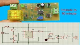
Hey guys welcome back in this video i'am going to share with you a simplest and most useful project. This project is used to protect your any electronics appliances. like mobile charger, camera charger, desktop pc much more. This circuit is based on a timer ic 555 . once you turn on this circuit this circuit will switching output supply is little delay time.
project requirements....
IC555
105j/400v capacitor
in4007 diode x 4
470 kilo resistor x 2
1 kilo resistor x 2
100 ohm resistor
12v zener diode
5mm red led
5mm green led
104 disc capacitor
10uf/16v capacitor
12v relay switch
bc547 transistor
Delay on circuit for DC supply Tutorial video • DELAY ON TIMER ⏲. USIN...
Schematic for this project
photos.app.goo...
"Thank you for watching! If you enjoyed this video, please consider subscribing to my channel for more content like this. You can also follow me on my social media channels for updates on my electronics projects and CGI videos. As a 3D animation maker, I have also uploaded my animation works on this platform.
If you have any questions or comments, feel free to reach out to me via WhatsApp at [8807649871]. Please note that I only accept messages and not calls.
Here are the links to my social media channels: 👇
[Twitter - As...]
[Instagram - ...]
Thanks again for your support! I look forward to connecting with you and sharing more of my work in the future."


Thank you. Very nice .I need circuit .
How can its delay time be increased?
May I download the video to watch it at my own pace? I already hit the thumb up :)
👍
Hello, thanks for the working circuit. Here, the bulb on's after a set time.. how to change of off after set time.. meaning.. when power on, bulb to on, then after time period set..it should off. Thanks
Possible only using microcontrollers. Like arduino
How about the ceramic capacitor?
I need it sir for my project.
Superb bro
Great and excellent work done Sir.Please Sir how many watts of load can this delay timer on handle?
Maximum AC load current: 10A @ 250/125V AC.
👌👌👌
Please share synmatic diagram of 5.1 amplifier
5.1 center voice speech filter circuit diagram making video next. Stereo Surround circuit diagram making video please😞😞😞😃
Soon as possible. Thanks for your requesting...
there is a ceramic capacitor missing in the circuit please make it clear..
Yes I know. But complete Schematic available in the description download link...
👍