Differential Amplifiers Made Easy

Вставка
- Опубліковано 10 сер 2021
- Support the channel! :)
/ theaudiophool
Differential Amplifiers are one of those circuits that can look a bit scary. But we will see today that if you look at it the right way, a diff amp is really no more complicated than the humble common-emitter amplifier!
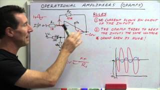
By understanding how a differential amplifier works, we will be ready to really delve deep into operational amplifiers (op-amps). The core component of an op-amp being a differential amplifier at its input! - Наука та технологія


Finally someone was able to explain it. I am not even exaggerating but i literally had tears in my eyes mid through the video because finally I am understanding the concept.❤️❤️
Your channel is a godsend. I'm in my 3rd year of EE and your content is finally linking everything I have learned with building audio electronics. Which has always been my main goal. TY!
You're explanations are incredibly clear - much more so than any other source i've found
Great walk through explanations. I’m sure at this rate I’ll have a decent synth by summer. Glad I met you mate.
God Bless.
Just found this channel, absolute treasure trove of information! Thank you!
Finally, a tutorial on Diff Amps from someone I can understand! Well done brother!
Had to watch it a couple of times but I finally got it. Eureka! Fantastic teacher.
Thanks for uploading.
thanks to your massively helpful videos along with some extra googling, i have been able to design my own tape saturation box with a discrete opamp output thank you so much.
Quite excellent insights and appraoch to explain the comparator circuit. It appears in an old power supply voltage control circuit (Coutant LQT 100) and your video is helping me digest and understand how it works to repair it.
Thank you so much. I come to watch your videos to refresh my memory since I had forgotten a lot after university. Your explanations are very clear
Hi from 12:52 and hi from me, an electrical engineering student 3 days before my exam in Electronics II. Thank you so much for this video!
Thanks for sharing your knowledge. I love the way you explain this.
Dude. I seriously appreciate your energy. This actually explained a couple circuit schematics I've seen, that I was kind of just taking on faith. Solid! You also walk a really pleasant line between approximation and reality that I find distinctly helpful.
"Walking the pleasant line between approximation and reality" should be my channel tagline or something! Love it! Haha :)
Thanks for watching!!
@@TheAudioPhool Love it, and the tutorials. This is phenominal work! I would love to see you go into some details about active loads, current mirrors and V to Current conversion.
WoW this is a GEM literally...thank you so much will never forget this bro!
Thank you very much for this video. I really appreciate your work.
Great video! Helps a lot!
thank you very much for such a great explanation! i finally got it
You are a really good teacher-- i am a guitar amp guy-- and have been looking for "long tail pair info"-- found it with your lesson thank you-
You deserve more Subs!
great work dude!
Yes ,the best way to illustrate and for people to learn something. You are genius. Another similar concept that even many experienced engineers still get confused and not understand is Gain and Phase margins. Similar illustration like it here would show it lucidly and clear the myth. Some calculation would be needed to zoom into where the frequency or the capacitive loads may cause oscillation. Many still doo not know what a signal oscillation looks lie, unfortunately. Thanks.
amazing video thanks a lot
Great video. I love it.
As promised! Nicely done. Til next time.
Very nicely explained ❤
I just subscribed this channel is awesome.
Thanks a lot Buddy!!!
This will be the first circuit experiment on my new basic research bench when I get it built. I am interested in how these magical little pieces of rock amplify signals.
Nice video, thank you for sharing it :)
Thanks for watching and leaving a comment!!
very good
Good stuff.
This is such a good explanation. Thank you!
@The AudioPhool Is there a chip simular to CA3046 but with pnp transistors? Thank you.
Hi can you make video on how one port and two port network synthesis applied practically on designing ckts like filters and amplifiers, thank you.
When you ground the base of the transistor wouldn't it be off? How does the collector of the off transistor produce signal?
The more I think about your analysis of input signals : you imply that for any two input signals of whatever shape they take, they can be decomposed into 1) sine waves in phase, same amplitude (the common mode content in the pair) and 2) sine waves 180 deg out of phase (what makes the input pair differ)...which uses the idea that any signal is a (complex) sum of sinewaves, and any phase shift is constructed from 0 and 180 phase sines with varying amplitudes? Sorry for the basic thinking here, but I find your tutorials very helpful to tease out my understanding!
Why you did not multiply the denominator by 2 in the G_common as in the G_diff ?
Excellent video! I now fully understand how these differential amplifiers work.
It only sems to you. Try to do experiment and you see that this is only illusion.
thank I understand
Thanks for the vids. very imformative! I have a question.....I have watched this video a few times, and still I am not sure I can follow what you say at 6:26. You are saying a "loop" (I assume, current) is going from the transistor on the left, through the 2 resistors, through the transistor on the right, and to ground. That's where I get stuck--I didn't think current could reverse bias through a transistor as you describe--on a NPN, the base > emitter appears to the world as a diode. But then again--I am a newbie....Do I have a fundamental misunderstanding of current flow through a transistor?
You're not wrong! The only thing missing from your understanding is the assumption that the transistors are on all the time, when the transistor is switched on we can think of the base->emitter junction as more like a very low value resistor, allowing the input to be placed 'across' both transistor's emitter resistors. When i say loop i mean a voltage loop in terms of kirchoff's voltage law. I think i mention this in my circuits 101 video :)
Key to understanding:
Remark :
Transistors are connected according to the common emitter circuit, in the OE circuit, the voltage at the emitter, roughly speaking, is always equal to the base voltage.
Since the potential at the point of connection of the emitters MUST be the same for both transistors, someone must give in ....
This small voltage difference falls directly on the PN junction of another transistor, closing it, that is, roughly speaking, if we assume that the transistor is open when the voltage across the BE is 0.7V, then with a voltage difference of 0.1V, we have a voltage drop on the other transistor on the BE 0.6V is not a completely open transition !!! This is equivalent to the fact that we stupidly applied 0.6V to the base. What will be the base current at this voltage?? Look at the CVC of the diode, the current will be almost absent, so the author talks about Eberton Moll's formula.
You can see the CVC of the diode, what current the LED will give out if its PN junction is not fully open, that is, if it is open at 2.7V, apply 2.6V to its legs and you will see that the current almost does not flow. So here, increasing the difference
Like this comment if it was useful for you so that others can see it.
So basically I could just calculate a common emitter amp and then mirror it with a matched transistor and use a ccs for Rx?
I wont lie my head is a bit spinny on that 1 mate,,love ur work tho pal,thanks.
U da man 👍
how to build differtial amplifiers without negative source ?
I remember the differential amplifier was made of tubes, called a Phil-brick Amplifier.
so where is the next video ? next week has been a month ago :D (just excited is all)
Haha! It's up now mate.
Really sorry about that, i had the video done but had to go away for a little while so i put it up on my patreon about 2/3 weeks aho but i couldn't release it fully without schematics and things!
@@TheAudioPhool dont worry, was excited and really love the videos :)
@@duality4y Loving the enthusiasm!! :)
Thanks for watching!
And you can explain it just like that.
im new to building DIY guitar FX pedals . i recently built a (Boss BD-2) Blues Driver ,it uses a discrete opamp for two stages in the circuit. i really like how the circuit sounds but i would like to understand how the discrete opamp works a bit better . im a bit confused on how the negative feedback works and how the audio signal flows through the discrete opamp ,I was wondering if you have the free time could you make a short video showing how the audio signal flows through and how the negative feedback works using the Boss BD-2 schematic . thank you for the videos i enjoy them a lot.
Are u electronic engineer
Proper english accent ... a white guy talking electronics, atlast :) ...keep it going man !
Won't it work as a stereo amplifier then?
Oh well
🤢
maths
Thank you for the videos🥲