Op Amps: Op Amp Internals

Вставка
- Опубліковано 22 лип 2024
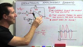
- In this video we examine the functional blocks that comprise a basic op amp.
References: Operational Amplifiers and Linear Integrated Circuits: Theory and Application; Chapter 2.
My free texts and lab manuals are available for download at my college web site www.mvcc.edu/jfiore and at my personal site www.dissidents.com
Inexpensive print and kindle copies are available at Amazon www.amazon.com/author/jimfiore
If you like my texts and videos, and would like to help defray the costs of making and maintaining them, consider making a modest donation at www.buymeacoffee.com/Professo... - Наука та технологія


Thank you. This is exactly what i was looking for. Everybody just describes what op amps do but not the internals. Would be cool to see the internals of popular op amps in their entirety
Glad you liked it. I remember thinking the same thing when I was first learning about op amps decades ago (when they weren't nearly as nice as what's available now). I never liked to learn things as a "black box". It's immediately functional, but it doesn't take you into the future.
@@ElectronicswithProfessorFiore I have almost a year of trying to learn electronics. It feels overwhelming sometimes, just soo much to learn lol.
Incredibly clear explanation! Thank you very much :)
Thank you professor! So very clearly explained!
Best explanation ever.
Great explanation. (TTL = Transistor-Transistor-Logic; I had to look that up, it means Through-The-Lens to photographers).
Thank you for the circuit diagram
Thank you for the explanation. This is the best I have ever had.
Not even studiying electrical engineering officially but now I understand all of it! Thanks! :D
I studying EE and this stuff is not easy, congrats.
Thanks professor
Hey Professor Fiore, I'm getting into making guitar pedals and I came across your video. Hope everything is well! ( I took your circuits one class back in 2018! )
Ah yes, I remember. Good to hear from you. That was the Engineering Science circuits class if I remember correctly, in the fall, right? What did you do from there?
I assume that you saw my video on guitar fuzz. If not, check this out:
ua-cam.com/video/zQcSPhM-G_U/v-deo.html
Hello! Thanks for the explanation. Just as couriosity. If the difference between the two inputs V+ an d V-, is equal to the total offset of the op-amp, in real conditions, wouldn't the output be zero ?
Yes, it would (ideally), but the trick with offsets is that you never what it is precisely. The manufacturer will give worst case and typical, but the values for any given op amp are unknown (unless you measure them).
In the real world, an op amp operating open loop (no feedback) is going to wind up in either positive or negative saturation, if you tie the two inputs to the same potential. Remember, the DC gain on one of these can be over 100k, so the slightest variation will push it one way or the other.
I understand how OpAmp amplifies AC but how it also amplifies DC voltage, its mystery. The same scheme that works for AC and DC. What is the key which forces to work the both way?
The key is that the circuit contains no lead networks (i.e., coupling capacitors). It's directly coupled, and thus, has no lower frequency limit.
Which one on the first schematic is + and - ??? Are they rechangable?
The diff amp produces an inversion as does the middle stage, thus, the lower input is in phase with the output (+). base->collector inverts, base->emitter doesn't.
@@ElectronicswithProfessorFiore Why the higher input is not in phase with the output when no signal is taken from the collector or emiter of the left part of the differential part?
@@incxxxx Because there's only a single inversion from that input to the output (via the middle stage). The opposite collector of the diff amp is in phase with the input under consideration. You might want to watch the videos covering the differential amplifier (found in the Semiconductor Devices playlist) for details. This is also covered in detail in my Semiconductor Devices text (free- see the video description for details).
At least it has a vgain option
I just never get how the class B stage "decides" how to saturate when we convert the differential input into a single current input from the first stage. The voltage gain stage in this case uses a single npn transistor, so the current will always be coming IN the base right? So haven't we lost the information of which of the two inputs was at a higher voltage? If I look at the power stage by itself, receiveing voltages as input, it's all fine but in circuits like this, I'm so completely lost. It just seems to me that as we get to the voltage gain stage we can only tell how far apart the signals are and not actually if the voltage on the inverting input was higer or viceversa.
Have you watched the diff amp videos? They might help. In any case, by the time you get to the final stages, you *don't* know which input was bigger, all you know is the difference between them. It turns out that's all you need, though.
@@ElectronicswithProfessorFiore Hey, thank you so much for the reply! I did watch the differential stage video and also have studied this circuit with an active load, darlington voltage gain stage and class AB power stage with SC and thermal runaway protections at my college. The thing that still bothers me is: if we don't know which input is bigger how is it the case that in the first numerical example it clips to a positive voltage and to the lowest in the second? If I were to swap inputs in any of these examples the difference between them would be the same, but still, I'd imagine the opamp would clip to opposite values...
@@themadnessofone9615 The magnitude would be the same but the polarity would be opposite.
@@ElectronicswithProfessorFiore That's the thing though: how is the information about the polarity carried through the system if the voltage gain stage accepts currents in one direction only? (as its input is usually the base of an npn or pnp transistor)
What do you mean "one direction only"? The input currents can be AC (and are, normally). You seem to be confusing bias currents with signal currents.
👍
I need someone to explain the base function. Like how does it gain? I'm im the second year of UNI and they just say "imagine this just magically does this" then just move on, that's when i'm fucked. I come from a hands on background. It starts off with, heres a hammer and a nail. Not Here's a hammer then a wall.
To understand what's going on inside the op amp at a deeper level, you need to go back to fundamental transistor amplifiers. Take a look at my Semiconductor Devices playlist. If you're familiar with the basic operation of transistors, you can start around "AC Model for a BJT". Otherwise, start back at "Intro to Bipolar Junction Transistors", assuming you're familiar with diode operation.
Is that class b or its ab
Class AB is just class B with a slight forward bias to reduce crossover distortion. I find it to be a subtle distinction. "Pure class B" is not really a thing. Virtually every amplifier advertised as class B is really class AB. Many people (myself included) tend to use the terms interchangeably.