Instrumentation Amplifier with Electronic Gain Control

Вставка
- Опубліковано 18 гру 2023
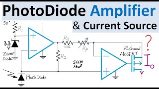
- Circuit Design and Analysis of an instrumentation amplifier with Electronic Gain Control is discussed in this example. This circuit is implemented with five operational amplifiers and two N-channel MOS Transistors also known as nMOS to realize linear electronic gain control for applications where Automatic Gain Control (AGC) requires electronic gain adjustment. For more examples see • Electrical Engineering... . The electronic gain control function can also be realized using JFET Transistors instead of MOSFET transistors. The input voltages in this precision amplifier can be the tiny voltage across an optical or thermal sensor that can't provide current. The instrumentation amplifier receives the input voltage and amplifies it to a reasonable level so that the drain of MOSFET is kept at low voltage to enforce MOSFET transistor in deep ohmic region of I-V curve. This is required so that FET transistor is effectively working as a voltage controlled resistor. The Circuit is analyzed and overall gain is computed using a combination of op amp virtual short, Kirchhoff's circuit laws including KCL and KVL and properties of FET transistor in deep linear region. Potential choices of op amps for instance from Texas instrument and Transistor from for instance TI or Nexperia are also discussed.
- Наука та технологія


Thanks for watching. For more Op Amp Circuit examples please see the list below. Note that MOSFET Transistor and Op Amp part numbers mentioned in video are only for illustration purposes and does NOT mean that they are proper choices for the specific reference voltage Vref value in this video. Depending on the chosen FET transistor, Vref needs to be adjusted to make sure transistor remains in deep ohmic region (so Vref might be required to be as low as ~0.5 volt). And for additional circuit examples see:
Op Amp Amplifier with Electronic Gain Control ua-cam.com/video/NoNgQpbj77Y/v-deo.html
VCA Electronic Gain Control (Part 1): Voltage-Controlled Attenuator Overview ua-cam.com/video/cFzYZsPEtP0/v-deo.html
Switched-Capacitor Amplifier Design: How does it work? ua-cam.com/video/n8UOTmPI4aI/v-deo.html
Op Amp Analog Computer Differential Equation Solver ua-cam.com/video/ENq39EesfPw/v-deo.html
Thermometer Circuit Design with Op Amp & BJT transistor ua-cam.com/video/55YsraFE0rg/v-deo.html
Push-Pull Power Amplifier with Darlington Transistors ua-cam.com/video/866MYibo8yE/v-deo.html
Analog Logarithm Computer ua-cam.com/video/RpKEq5WyoLg/v-deo.html
Lowpass Butterworth Filter: ua-cam.com/video/UzCjkwqy-9w/v-deo.html
Analog Computer to Raise Signal to power n ua-cam.com/video/IUTlBH1UraE/v-deo.html
Triangle Oscillator Op Amp circuit ua-cam.com/video/JF5Up_cuL9k/v-deo.html
Differential Equation Solver Analog Circuit ua-cam.com/video/R3X5AYNZGEI/v-deo.html
Complex Sinusoid Oscillator ua-cam.com/video/GXRhmwmS5Zk/v-deo.html
Sawtooth Waveform Generator design with OpAmp, JFET, BJT ua-cam.com/video/5zHXTx-Vl20/v-deo.html
op amps Circuit with feedback loops to design an analog computer that solves a second order differential equation ua-cam.com/video/HeZRtnRXpEI/v-deo.html
For more analog circuits and signal processing examples see: ua-cam.com/play/PLrwXF7N522y4c7c-8KBjrwd7IyaZfWxyt.html
I hope these Circuit design and analysis videos are interesting. 🙋♂
Hi. I've spent the afternoon watching a lot of your videos. Great stuff! Thanks. A minor issue with this one - I believe your very last expression for Vo is actually Av, since V2-V1 is absent.
Thank you for watching, your interest, detailed attention and your follow-up comment. I am glad that you like my videos. You are right, in that very last example equation around minute 34:30 I inadvertently dropped the (V2-V1) in the denominator while present the specific Av value assuming Rf=100kOhm. Thank you. For more examples please see: Op Amp Amplifier with Electronic Gain Control ua-cam.com/video/NoNgQpbj77Y/v-deo.html
Analog Logarithm Computer ua-cam.com/video/RpKEq5WyoLg/v-deo.html
Power Amplifier Design with Transformer ua-cam.com/video/gKlJrqGqeCI/v-deo.html
Op Amp Analog Computer Differential Equation Solver ua-cam.com/video/ENq39EesfPw/v-deo.html
Instrumentation Amplifier with Electronic Gain Control ua-cam.com/video/C4tghZ-q6Zs/v-deo.html
Push-Pull Power Amplifier with Darlington Transistors ua-cam.com/video/866MYibo8yE/v-deo.html
Thermometer Circuit Design with Op Amp & BJT transistor ua-cam.com/video/55YsraFE0rg/v-deo.html
I hope you also enjoy these further examples. Thanks again 🙏
Definitely brings back college circuit courses, and with additional experience it makes so much more sense. I immediately thought of this as a gain control for an audio preamp. I increasingly find the need to control preamp gains remotely and have found it difficult to do without injecting noise. As we network audio systems they become more distributed and gain controls are no longer practical to have at the location of the microphone input. Being able to adjust them remotely for system gain stage balance makes more sense, even though most manufacturers are not yet doing it. This is an excellent example of one way to do it. Thanks for the thorough derivation.
Thank you for watching and sharing your insights. Glad that this Instrumentation Amplifier Example is useful. For more examples please see ua-cam.com/play/PLrwXF7N522y4c7c-8KBjrwd7IyaZfWxyt.html
As you mentioned, Remote or Automatic Gain Control (AGC) are among the applications of this circuit. We can use this peak/RMS detector circuit ua-cam.com/video/4aG5NYX8tGo/v-deo.html and then compare its output with your desired peak/RMS level and then adjust the gain accordingly.
Thanks again for watching and your interest. 🙏🙋♂️
Some mention of the distortion that may be created by the NMOS gaine control would be VERY valuable.
Thanks for watching, sharing your thoughts and suggestions. You have a good point. I had a lot to cover in this detailed long video and packing more topics was concerning. A related example is ua-cam.com/video/NoNgQpbj77Y/v-deo.html . I will post more Amplifier examples in my Circuit Design/Analysis repository ua-cam.com/play/PLrwXF7N522y4c7c-8KBjrwd7IyaZfWxyt.html . Thanks Again 🙏
Thank you. I like your way explaining analog electronics very much. 👍
Is it always the case that MOSFETs or other electronical parts, which are siting on the same silicon chip, are matched?
Thanks for watching and your comment. Glad that you like my videos and they are useful. Answering your good question: Not necessarily, there are many forms of mismatch between electronic components. The severity of mismatch depends on the component, package and design. Having component on the same substrate in the same package helps with reducing the mismatches hopefully to a level that is acceptable for a given desired application. For more circuit examples involving matching transistors please see:
Wilson Current Mirror and Current Source Design Tutorial ua-cam.com/video/LfbfJYrovN0/v-deo.html
Thermometer Circuit Design with Op Amp and BJT transistor ua-cam.com/video/55YsraFE0rg/v-deo.html
Op Amp Amplifier with Electronic Gain Control ua-cam.com/video/NoNgQpbj77Y/v-deo.html
Anti-Log Analog Computer with Temperature Compensation ua-cam.com/video/kk2c7Gk3nW4/v-deo.html
I hope this explanation and these circuit examples are helpful and interesting.
To see more electronic amplifier videos:
1x, 10x, 100x, 1000x Switched-Gain Instrumentation Amplifier ua-cam.com/video/9-MLqyewXW8/v-deo.html
Variable Gain Instrumentation Amplifier for designing Thermometer Current Source ua-cam.com/video/Ggf0yCaTTiY/v-deo.html
Instrumentation Amplifier Explained ua-cam.com/video/Yq767et8BbY/v-deo.html
Gain & CMRR of Instrumentation Amplifier Explained ua-cam.com/video/Bw29QjHHzGo/v-deo.html
Instrumentation Amplifier design with Differential Instrumentation Amplifier with BJT transistor ua-cam.com/video/2xJpqfexsPg/v-deo.html
I hope these videos are helpful
Thank you for this fantastic, in-depth video.
When I saw this, I immediately thought of an audio compressor circuit. We could get the peak of the input signal using an ideal diode circuit in full-wave rectification. Now, the only problem is that this circuit amplifies the signal. If I wanted a damper, I would need to have an inverting second stage, with the FET as an input element.
What is your opinion? Should I use a single FET with a biased signal or two FETs in a push-pull configuration with both gates driven by your first stage? Also, crossover distortion will be problematic if I'm not biasing the input sound.
You're welcome. Thanks for watching and your follow-up comment. Glad that you like Instrumentation Amplifier Video. As you mentioned, Automatic Gain Control (AGC) is one of the applications of this circuit. We can use this peak/RMS detector circuit ua-cam.com/video/4aG5NYX8tGo/v-deo.html and then compare its output with your desired peak/RMS and then adjust the gain accordingly. While there are many methods to implement full-scale AGC circuit (much more capable than this core concept example), my suggestion is a quick scrappy work-around here (to achieve your design) by adding an additional attenuating stage at the output that by default is attenuating to lowest level that you might need. Then the matched-FET gain stage just works as a gain controlled stage that counteracts the default attenuation as much as needed to get the signal to the right level. For more circuit examples please see my Analog playlist ua-cam.com/play/PLrwXF7N522y4c7c-8KBjrwd7IyaZfWxyt.html
I hope this is helpful. 🙂
@@STEMprof Thank you again for this extensive reply. It was really helpful. This approach sounds more optimal with respect to semiconductor count, so I'll start the design this way.
You are very welcome. Thanks again for watching and your interest. Best wishes with your circuit experiment. 👍🙋♂️
Could you please also mention where is this circuit is being used in the practical circuit/ World......your videos are very good but why are we studying particular circuit that should be clear....
Thanks for watching and your comment. Glad that these circuit videos are useful. As mentioned in video, precision gain-controlled amplifier for instance for optical sensor is one application especially when Automatic Gain Control (AGC) is desired that requires Electronic gain adjustment. For more circuit examples please see my Analog playlist ua-cam.com/play/PLrwXF7N522y4c7c-8KBjrwd7IyaZfWxyt.html
I hope they are interesting and useful. Thanks again. 🙏
It can be used in the practical circuit (world)😊
@@qemmm23 Thanks for watching 🙋♂️