Tachometer (RPM Meter) || DIY or Buy || How a 3€ sensor outdoes a 29€ product!

Вставка
- Опубліковано 25 лип 2024
- $2 for 2Layer, 5pcs & $5 for 4Layer, 5pcs: jlcpcb.com
Previous video: • HACKED!: Turning an In...
uC Timer video: • Electronic Basics #30:...
Facebook: / greatscottlab
Twitter: / greatscottlab
Support me for more videos: www.patreon.com/GreatScott?ty=h
More project information (schematic, code,....) on Instructables: www.instructables.com/id/DIY-...
Parts list (affiliate links):
1x Arduino Pro Mini: s.click.aliexpress.com/e/_dTW...
1x IR Distance Sensor: s.click.aliexpress.com/e/_dXl...
1x 128x64 OLED: s.click.aliexpress.com/e/_dXO...
1x TP4056 Charge Protect Board: s.click.aliexpress.com/e/_d69...
1x LiPo Battery: s.click.aliexpress.com/e/_dUE...
1x Toggle Switch: s.click.aliexpress.com/e/_dZ1...
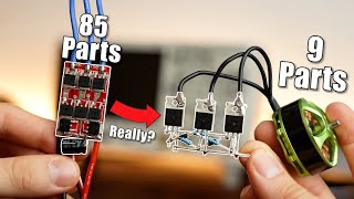
In this episode of DIY or Buy we will be having a closer look at a commercial tachometer (RPM Meter) and test it in order to find out that it is pretty much unusable. Afterwards I will show you how a 3€ IR distance sensor works and how we can use it to build a proper DIY tachometer that functions properly. Let's get started!
Thanks to JLCPCB for sponsoring this video
Visit jlcpcb.com to get professional PCBs for low prices.
Music:
2011 Lookalike by Bartlebeats
Killing Time, Kevin MacLeod
(incompetech.com) - Наука та технологія


Sadly there is a small mistake in the video. The IR photo diode is positioned the wrong way around. Just imagine the cathode and anode being flipped. Sorry. (Edit: Ok, there is a second mistake. I used the roller adapter in contact mode incorrectly. I just did another measurement the correct way and measured an RPM of 270 while the correct one would have been 230. So this way it was a bit better but still not good enough for me.)
But who knows that? I tried searching for information on that but not even the official manual of the product bothers to mention those details. I think most people would use it like I did.
Ok. I just tried it this way and the result was better. I got 270RPM with the DC Motor which actually rotates at 230RPM. So still not good enough.
@@greatscottlab Great job, love your vids man, keep it up!
@@greatscottlab Please make videos for the same project but with a new feature to turn ON a led when the speed reached 40 kmph. Awaiting...thanks in advance.
@@greatscottlab Please make videos for the same project but with a new feature to turn ON a led when the speed reached 40 kmph. Awaiting...thanks in advance.
Now you‘re just missing a 3d printed case for it and then it would be perfect 👍
Agreed but I would change the layout some to be a bit more compact.
You mean"compact"?
@@111genti yes ty new phone and it puts what it wants LoL 😂.
I thought about it but decided against it in the end to keep it simple.
@@greatscottlab Good decision to make it simple.
One of my favorite parts of your videos is watching you write. Your handwriting is impressive!
I laughed when see you're sponsored by JLCPCB but build just using perfboard.
For prototyping, why not? Want to make a batch of faulty boards? He use them often.
LMFAOOOOO
@@bryanst.martin7134 they seem fine to me, ive ordered some pretty sketchy looking boards and they still worked fine
0:52 it's kind of cheap for tachometer in comparison to others
The $16 tachometer down there:
Delievery charges ... 100$
Great video, very informative and practical.
Just a thing I noticed, because I stumbled over it not too long ago myself: The two pixel white strip to the right of the OLED (10:03) is most probably caused by a wrong display type. If you have a SSD1306 but initialize it as a SH1106, or the other way around, you get those strips.
I really like the way how great scott explain electronics without straining the time limits of his videos.
Men the diameter of the rolling thing is affecting the values , smaller more turns bigger less turns, you got to used aligned, not in besides
Yup, in contact mode, the tacho will be accurately measuring how fast the tacho's shaft was turning. To measure the speed of the shaft, push the contact rubber onto the ene of the shaft, not rolling around its side.
The user manual would have made this clear, but it was probably in impenetrable chinglish.
Edit: someone else picked up the reason why it failed with the optical - insulation tape's optic properties are horrible. It is designed to be used on the bare shaft of the motor. If you need to add anything to make a mark, try painters masking tape.
To use contact mode you must put the probe coaxial with the motor shaft not side by side like a spur gear arrangement. Great video tho!
He tried that too, wasn't accurate either. 4:12
I was looking for this comment.
What you're saying is correct, But in this case laser tachometer reading incorrect RPM value, Diameter comes into account when we measure travel distance of shaft m/min.
DIY wins
I have always loved your constructive approach to electronics and making things in general. you inspire me alot. keep up the great work Mr. Scott
Yes! DIY wins!!
I always wanted to do this project and find out how accurate these IR sensors can measure RPM. Thanks for doing it for me!
You've got the best left hand writing skill I've ever seen. You're a phenomenon !
Once, I made a tachometer using a hall sensor effect and a magnet, but this way with the IR sensor, looks much better. Great job!
A tip for expansion later: Add a graph of the rpm over time on the lovely Oled display! Would be nice to see if rpm oscillates on things as well! Very few meters can do that.
I love it when DIY wins , great work scott !
i love to see diy win . it so happy our own made product work so fine . i give joy and emotions own hand made things
That's again is a wonderfull video. I like the DIY or BUY series. Over the past few years, I more often to go DIY. Not just because it's cheaper and I learn while building, but also because I can repair easily and recycle parts if I don't need the device any longer.
Thank you for all the fresh ideas.
My actual project is a weather station that saves the weather data to an NAS. So I have the complete history available and have at the same time a better accuarcy for temperature, humidity and rain quantity than I got from standard weather station. As a side effect I can easily display abolute air humidity or dew point, which is not available at normal weather stations.
I also plan to display a recommendation for room ventilation based on comparing temperature and (absolute) humidity.
The internal (display) part might be upgrated by an air quality sensor in the near future, which will improve the ventilation recommendation.
WOW, what a hugely impressive project! I continue to me amazed by your talent, and top of portraying everything in a really great and digestible way. =]
We need more diy winners very nice video keep up the good work
Your content is about very useful tools and stuff we can diy
Keep it up:)
thanks Scott.. Video very clear, complete, complex and so on... See you next video...
@GreatScott. Thank you for including the Entire Creative Process, including misadventures and commenters input. Makes for a more interesting and interactive experience for me. I use DC motors and motor controllers in the Mobility Industry and am drawn to invasive videos such as this. Thank you and your excellent commenters. Too bad I caught this one so late. I blame UA-cam for poor notification.
One of the best videos of 2020
Nice!!! I will make it!!!!! I love this projects. Good job mate 😉
When you building meter, you have to dealing with non-linearity, error rate, accuracy, precision, and more. It's a whole study case
Thanks for this , I built it but was getting twice the rpm my scope said ! I have changed 120 in the code to 60 and now it works perfectly.
Thanks for a great project.
I am going to run it off of an 18650 a fuse instead of the charging board . On the occasions I want to use it I will put in a battery. This keeps costs down for something it will use now and again.
Really you did hard work, worthy to watch complete video . Excellent 👌
Thank you so much for this project i was looking for this thank you so much 💓😊
ganz ehrlich, jedes mal wenn ich dir bei schreiben zu gucke bin ich wieder aufs neue fasziniert wie du jedes aber auch jedesmal den selben strich triffst, eins wird sicher sein, du hast kein parkinson :D
With the contact sensor you have to multiply the reading for the "gear ratio": calling 1 the shaft to misure and 2 the roller sensor, omega_1=omega_2*Radius_2/Radius_1
(Infact in your example the radius of the shaft are circa a half, like the rpm misured)
For me the contact method (if applied correctly) is the more precise as long as don't putting too much contact force or/and if the sensor itself have a lot of friction (could be a problem for low torque or very high rpm motor)
I Just loved this project
Thanks for making it
Excellent, great with great details there is no any misleading information.
Great project with really good explanation.
Your Intro is awesome 😍
Nice job. Great project.
Im using the same sensor for al kinds of counting stuff, quite accurate if you do you coding well, well worth the effords thumbs up for the video !
Thank you. This will come in useful: I'm building a shaking water bath and needed a way to calibrate the shaking.
Thoroughly enjoyed this one :)
Super cool vid!
I like ur writing and explanation
Yeeeeeeeees next awesome video!
For contact RPM counter, it's preferable to use IR encoder for accurate measurement. In non contact Measurements many factors affect the accuracy: angle, light, stability of both (the tachometer and the rotor).
Nice video. When RPM is low switch from time per pulse to pulses per time. I once harvested IR LED pig-snout pairs (may have been just me that called them that) from VCR's for this. VCR's used them to monitor reel speed and designed more so the LEDs were hidden from each other. They seem rare these days.
I can't find the code
Thank you! I’ve been needing a better tachometer for a while but I just don’t want to spend the money on one. I already have the components you used so I can make it right now.
Even for the laser measuring part, you still messed up, you are supposed to attach a wheel to the end of the shaft and use the flat side for color differentiation (like this ◐). Doing so will give an instantaneous signal change instead of a gradual one when you tape on the round shaft.
For some reason, your tachometer didn't come with some reflective tapes, these are like the ones on the trucks and provide better contrast.
Brilliant idea. Good lateral thinking!
It's great, Scott!! Thanks a lot
I bought a similar RPM counter 10 years ago. It came without any of the accessories. ("Digital Laser Tachometer with Pouch (2.5~99999.9RPM"). When I measured a 5400 RPM hard drive platter, the display read 5399 - 5400.
old stuff what prolly much higher quality
did it cost more?
☆Awesome☆ You are a real pro!
No way scott i was making one
This will be very helpfull!!!!!!!!
Tysm
great video as always ! :D
Excellent video keep it up .
Clearly a WIN for DIY !
Timer capture peripherals are awesome. I use them extensively.
Just talk about the pens you use sometime.😂 hand writing is soooo smooth!!
Lookup stabilo pointer.
@@tokk3 Stabilo Point 88 :-)
@@greatscottlab I guessed so. Wasn't completely sure.
Quality German pens.
I use them too.
Wow Sir, Great project 👍🔥🔥
Thanks for reverse engineering the circuit of the module! I used your schematics to figure out how to add hysteresis (Schmitt trigger) to the circuit: You can easily add positive feedback to the comparator by adding a resistor between the output and the non-inverting input.
I just soldered a 20k resistor between the OUT terminal and the anode of the Photodiode on the backside of the PCB.
I did this because I had problems with false interrupt triggering on an ESP32 using this module. Apparently the ESP32 external interrupts need a quite fast rise time to trigger reliably. It would have been interesting to see how noisy the rising and falling edges of the signal in your setup are by zooming in on the DSO.
The 20k might not work for all sensitivity settings of the trimmer pot. To change the hysteresis it might be a good idea to replace the resistor with another trimmer pot.
Great video as always. Thanks
nice project dude keep it up
Back in my model airplane days some 20 years ago I used a Tower Hobbies optical tachometer to measure the prop speed of my glow engines. It could be set to read the speed of two or three-bladed props. Some of my engines could go as high as 25,000 RPM. I used to check its calibration by pointing it at a fluorescent light to read the line frequency. Seemed to be quite accurate so I never questioned the readings. The only mod I made was to fit a small flat-black painted tube made of cardboard over the sensor port to keep side-light from swamping the sensor, which only used reflected light - no laser. Oh, and I don't think I paid more than $20 for it back then.
I miss the good old days when great scott used to make prefboards with clean satisfying soldering
I wonder why didn't he choose a veroboard rather than an ordinary perfboard. I think veroboards are better for semi-prototype stuff since their traces resemble solderless breadboards...
@@rizalardiansyah4486 Nevertheless you can still get decent solder traces with prefboard too
I'm so going watch all your videos today.
Forget about Marvel or Disney....thanks for great entertainment.
I hope you read this. Please consider making a 3D printed 8th order bandpass speaker with a (hidden) 4.5 inch driver to 250-300Hz with port on same side as a 2.5 inch driver for the rest of frequency range and design a proper crossover for that design. We all learn about crossover eventually and now you can be authority and overcome previous mistake. We love your videos and your excellent efforts.
WAS WAITING FOR IT
Danke für das Video!
I used a Hall sensor to make my RPM counter it also works flawlessly
Very nice idea👍👍
Great video as always
Thanks for sharing :-)
Hey GreatScott!,
Congratulations on the project, it looks really neat and outperforms commercial equivalents! However, there is a small, 2px wide band of noise on the right side of your display. Its probably due to the display controller being a SH1106 - a "SSD1306-compatible" driver which has 132 px wide display RAM (contrary to SSD1306's 128 px). Most of the libraries and tutorials out there focus on the SSD1306. To fix it, either switch to SH1106 in the graphics library or just find the function which transmits the cursor address and add a permanent +2 term to the x coordinate. I had the same thing literally yesterday so I noticed it immediately.
MfG :)
sometimes I wish UA-cam has a like button in full screen mode on my laptop. Nice video!
Homemade products are the best, greetings from Mexico
wow, super erklärt. und diy ist schneller und preiswerter. danke mfg ralf
I think your video is great! I can tinker with Arduino. I draw with the elek. CAD and then I can order JLCPCB. Perfect! 👍😉😊
We use an adjustable stroboskope light. If the shaft seems like standing still you can calculate the rpm.
Inspector gadget awesomeness! Neat what can be measured with the audio and/or video editing software. Those methods alone might even be worth video? Excellent detail as always. Thanks for sharing!
very cool video!
So basically you're using a digital counter in front of a shift register - pretty ingenious! The output display can be stabilized more by using a rolling average of the previous three measurements.
thanks for sharing the project
I found using old IDE cables make running traces so much easier. You can make a ribbon as wide as you need. Bend it wherever you want. Lays flat.
Cool Video!
Yep...another project for me! Thank you!
use infrasound detector app from android playstore.
put IR receiver in headphone jack.
power IR emmiter by small button cell.
it works really well
Nice, I really like it
Nicely done
Just got mine to work : = )) Had to change the resistance pot some to get to start reading.
Next on DIY or Buy: The differential probe
Would be nice to see GreatScott attempt to build one :)
Pretty nice work, dude! Really well done! 😃
I'm going to build one of those for me as well!!! 😃
Anyway, stay safe and creative there! 🖖😊
use infrasound detector app from android. put IR receiver in headphone jack. power IR emmiter by small button cell.
it works really well.
Very informative video.
You are great, I will try this :)
Who else starts their Sunday morning with a cup of coffee and a slogan of " let's get started"?
Normally but I'm cranky today!! I forgot to buy coffee yesterday.
@@PerKroon coffeeless mornings is never a good thing 😭
Sorry not the age to drink coffee but soon I can taste it😁
More like coffee evenings in Germany
@@yxcvbnmmnbvcxy544realistically, it's a 24/7 affair 🤩
Gets me going at 8:00 a.m. keeps me up until 3:00 a.m. coffee coffee coffee!!!
Hi Great Scott, I have the feeling that you missed something in the measurement of the rpm by contact. Indeed, your tachometer measures the rpm of its own head, and thus you must introduce a correction coefficient as the rate between the rotor head diameter and the tachometer head. The tachometer cannot know what is the diameter of your shaft!
Read my pinned comment.
But then the IR Sensor is the better solution anyway. No need to calculate something...
@@greatscottlab There is no pinned comment :(
Exactly! The "by contact" probe should be touching the motor axis in such a way that both rotate at the same angular speed: they mustn't touch side-by-side, but tip-to-tip.
I see it. Says that it's been there for a week.
He doesn't go into detail but he said that he figured out he was doing something wrong and retested, and that it was closer but still had some error in the measurements.
If you use a bigger prescaler value in your timer or also count overflows between measurements you could get a lower minimum RPM.
Great video... 👍
I never thought that IR distance sensor was so fast and useful
cool video!!
I had once made RPM counter with telly counter & Reed switch
Learned a lot more in new video
And I just ordered mine before seeing this video... :D but it's worth to try the DIY one.
Thank you for the author's release, very practical test device, very suitable for professional technicians: electrician/car repairman/industrial...etc, I like this project, I will create and assemble a 3D shell (There is no need for any circuit board PCB, as long as the distribution line is enough), it will not be long before I will post a comment on the shell 3D printing to stl to share with everyone
Thanks for sharing!
@GreatScott! Amazing video as always :). I just have one doubt though. In your explanation, you are saying 60 / (rpmtime / 31250), whereas in the code, you are using 120 / (rpmtime / 31250).
A year ago I had a similar project. I had quite the Problem with the accurate counting, because the Arduino was too fast and produced overcounting because the interrupt was triggered several times at the edge of the tape. I had to use a delay of some us to avoid double counting of rotations. I am rather surprised that your setup worked so well for you.
Hi, i'm currently working on the same kind of tachometer (using mega8 uC, LCD, and the same IR sensor). By inaccurate counting i assume its external interrupt triggers several times while the object passes only 1 time?
while testing the IR sensor, i realized after i tried to wave my hand 1 time in front of the sensor, the interrupt count suddenly increments by 4! (and sometimes even 6 lol) this led me to assume that the output of the IR sensor itself is bouncing. (and i dont have oscilloscope to check this since i'm still a student)
this issue is solved after adding some RC network to debounce it, and the IR sensor triggers the ext interrupt now correctly (for example i waved my hand 5 times in a fast manner, and the count increments exactly 5 counts)
Hope this helps and I'm happy to accept any advice too, thanks~
@@yeyee2418 Hi Yeyee_Gabriel_S_,, seems your solutions can work with me too,, but I'm lack of information about how to connect the RC network to the IR Sensor output,, any reference or some wiring diagrams that I can accessed?
Thanks in advance,,