Andreas is the best, I just stand in his shadow - which is a very big shadow considering that he is in Switzerland and I'm in Canada! But I do thank you for the complement.
don't do yourself short! i like your videos like the ones from andreas. I'm looking forward to your connection between a pi and an arduino. I want a (double) car-detection & aid (distance to the wall 4 my wife) in my garage directed by an pi (connecting to home-assistant) and measured with an arduino. KUTGW!
@@sledgeHammerRulez That is an interesting idea. I think I will make an arduino based ultrasonic sensor for my mom that tells her when she has pulled her car alll the way forward in the garage.
I thank you for your excellent explanation of the programs you use. You go through each and every line of code in precise detail, and that's exactly what I need. So I can't thank you enough for your attention to precise detail. Also I totally agree with "I Two C". That's perfectly acceptable and how I pronounce it too. I understand that "I Squared C" is also acceptable, but like you, I actually prefer "I Two C". Because in truth, there's nothing mathematically squared about it. You are an excellent instructor far above the norm.
I truly enjoy your videos and instructional style and was pleasantly surprised to hear you mention my original favorite UA-cam teacher with the Swiss accent! The sinister part of me was waiting for you to coyly explain that the reason you decided to build a custom 4-way ultrasonic I2C sensor (unlike Mr. Spiess' 3-way sensor) is simply because 4 is clearly better than 3. Maybe zoom in to picture of two groups of puppies where 4 is clearly better than 3. No smiling, just more matter-of-fact presentation of your analysis. I'm kind of glad you didn't as I would be cleaning up a cup of coffee right now. But seriously, thank you for sharing your knowledge!
Very good video again! For everybody complaining about I2C or I square C, please start your own channel and do a better job. I wish you all the best but doubt you will succeed. Keep up the good work! Love IT!
Thank you Robert, it can be very dishearting to put the effort into making a video only to have some clown critize it for something as silly as "I squared C" vs "I two C". Especially when neither of them are technically correct - it's the Inter Integrated Circuit bus so it should probably be "IIC"! Maybe I should have just said "TWI" to avoid offending Mr. Perfection. I really appreciate your nice comment, hopefully there are others who feel the way you do. Thanks!
@@Dronebotworkshop the problem is that it is not possible to satisfy everybody. But nowaday it is so easy to BASH that you could be discouraged tot make this video's. Well I happen to love them andere learn a lot. Hope this helps to continue! Thanks
Thanks Man! I am a teenager in to come in 10th, and with your help, I've made my very own I2C Keypad 4x4 Matrix and made a smart keypad door lock with it. I am going to make a PCB for that. Thanks a lot.
Outstanding tutorial. Clear, concise and fun to watch and learn. So being that I'm from Southern California you get the "woohhhoo Awesome Dude....you made I2C gnarly" award!
This guy is fantastic! The two I2C vids are really good, best I’ve seen! Hoping he also does the other available interfaces...highly recommend this channel...
Bill - WOW! That was an amazing tutorial. I know feel confident that I could change my own sensors to be I2C items. It's like I can create a wired version of MQTT where I don't need wireless. Thank you do much for doing such a patient and well thought out tutorial.
Awesome ! I've been using an ultrasonic sensor on a servo that sweeps left to right to avoid obstacles. The noise of the servo drive me (and many others) crazy. This solution is really silent ! Much better.
Hi, Bill! I just wanted to reach out and thank you personally for covering I2C, because that first episode in particular helped me learn a huge amount on the topic! I was able to massively overhaul the hardware and software of a project I'm working on for an up coming convention. I previously had an ATMega328 running animations on about 120 neopixels, while reading buttons on a control panel and polling a potentiometer for a brightness control. Since learning about I2C and how to implement two way communication between two or more microcontrollers, I've been able to use one ATMega to run the light animations, and second ATMega running the control panel. I've also been able to swap out the potentiometer for a rotary encoder AND implement IR remote functionality using a cheap slim pocket IR remote, since I learned from your videos how to use IR control in projects :) I hope you know how much you've taught people and inspired them to try new things :D Take care of yourself :) ~Azy
Simply amazing tutorial. As the newping library is available on platformio, I'm moving to visual studio code with the platformio extension instead of the arduino interface - seems a much nicer programming environment. Thanks for sharing your excellence!
andreas, the guy with the swiss accent, did an excellent video on it last sunday! I will switch also, since visual studio code is now available as addon for home-assistant as well
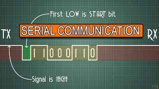
thank you! at 3:50 bit zero is mentioned, but the timing diagram shows bits one through bit N - is the diagram off-by-one - or Also it is stated "the clock signal will go high every time a data byte is sent" - perhaps sometimes you mean a single data bit?
@@vtorsi610 thanks perhaps that is what is confusing - the clock is shown clocking individual "bits", but the audio is using the word "byte" - the audio clearly shows the clock for the start "bit" - confusing use of bit and byte The wikipedia timing diagram uses the word "bit" for each clock transition - very similar image en.wikipedia.org/wiki/I%C2%B2C#Timing_diagram
The readI2C() in the video isn't waiting for 100ms, it's waiting no more than 100 ms. You will break out of the while if either there is something available or you are greater than or equal to 100 ms. You then do the read only if the elapsed time is less than 100ms. The return from readI2C() is undefined if more than 100 ms occurs between the request and the waiting for a response. It only reads and sets bval if there is less than 100ms, if it is more than 100 ms you return an indeterminate value.
Thanks for wonderful explanation and demo on I2C. Please explain on SPI compared with I2C difference, applications. Finally About UART, CAN bus as well.
Many thanks for your videos. Very informative. One topic I would be interested in a video on which continues the I2C learning is whether it is possible to use I2C within an ISR (interrupt service routine). It would be useful say if a RTC (real time clock) was able to be read in an ISR as millis() does not function. This could ideally go into detail about when and how interrupts are used in I2C comms. Geoffrey, New Zealand.
Yet another really great tutorial. I did have a question about your explanation of the protocol. As you describe the data being clocked on the SDA line, you mentioned the data as being sent in bytes. I think you really meant to say that data is sent bitwise until 8 bits are sent whereas the slave can then ack or nack the byte sent. Any number of bytes and be transferred during a transaction until a Stop or Restart is encountered. Once again, really love your videos.
When talking about sending data, you say data bytes (segment around the 4 minut mark), when I assume you mean data bits. The SDA-line can only contain one bit at a time...
Awesome content! Thanks for these videos! On a side note - during the first few minutes of the intro it looks like you have cat ears thanks to the pliers on the peg board behind you. Easter egg or not - still found it pretty neat... 👍👍
Yes, this video (as your other videos) definitely inspired me to create my own master and slave I2C project. Thank you for providing the explanation and the code. :)
I'm messed up with the theory part, what i think is the CLK signal toggles when a bit sent, not a byte. Also i expected a example communication with different sensors through I2C in the last part of the video, but it turned out to be just a combination of this and the last videos.
Like your quality tutorials. I have a question. Since you are going to send back 4 bytes of sensor data, why not just ask for 4 bytes on the master request and then have the slave just read the 4 HC-SR04's at that point of time in the order of 1, 2, 3 and 4. All the other reading between requests will not do the master any good. BillW
@@vtorsi610 he's asking why wait for 8 bytes if the slave only sends 4, if you read all 4 sensors in a defined order and pnly wait for 4 bytes instead of 8 then the communication time slave to master is halved making it possible to respond faster to sensor input.
I have some problem trying to understand how the readings from the sensors remain synchronized. How the Master can always recognise the 3rd sensor as the third?
Bill, I actually followed a lot of what you said! I got confused a bit at the beginning but as you went through the sketches I kind of got it! It amazes me how you can make things understandable to me in my current condition.. I am so thankful. One thing I do not understand is why use i2c? everything seemed work ok before you added the second arduino? I did not understand what the advantage was.. Sorry if my questions are rather childish.. But I do have such a hard tome understanding things here in my later years.. Sheesh it never used to be this way.. Well thanks for the share and carry on my friend.. oh one other thing.. I got the DroneBot workshop news letter on april 8th has thee been a new one? or is it just once a month? I have forgotten..
It's not clear here why a data-based protocol (the 255 marker) is being used instead of multiple byte reads/writes. Am I misunderstanding the I2C spec, is it an issue with the library, a robustness issue, or something else?
shouldn't the code be if(millis() - entry > 100) bval = Wire.read() instead of if(millis() - entry < 100) bval = Wire.read()? To show that the time has ellapsed
A caution regarding the HC-SR04. There is now a "p" version of this sensor (recognized by the missing xtal) that does not work in one wire mode. only in two wire mode.
Thanks for this video! How would you build a system that has upwards of 60 sensors? I2C should allow them all to be connected serially, without requiring a connection from each back to the arduino as you’ve done here, right? Would each sensor need its own microcontroller in that case?
You will definitely have a significant delay if you will use one Arduino Mega and wait for each one to measure, if you can read all of them at the same time ( assumming they will not interfer with each other ) just scale the code to acomodate all of that data, from my experience with 20 sensors and a master and slave ( 2 Megas), it was not a problem. Btw why do you need so many ?
Like all of your videos, also this one is very educational. Thanks for uploading!! But how do you approach the problem if you want to transfer 128 bytes from a slave node to a master (e.g. Arduino or Teensy)? Do you know of any link that might help me with a code fragment?
@@Dronebotworkshop And that mentality is the difference between your channel and all the other hobby electronics channels on YT, most of which are not even half as well constructed nor half as informative.
Thanks for the excellent video, I have a question though hope it is the wright spot to ask. My understanding from the video that due to address conflict we cannot connect the 4 ultrasonic sensors to the same I2C bus because all of them have the same address?
sir in my project i want to send string variable from master to salve and multiple sensor data is need to send from salve to master(master is node mcu and salve is arduino uno)
Something is wrong with i2c master sketch doesn't compile for windows says expected initializer before j token right at void set up any solutions would be greatly appreciated thanks😁
You are right. Sending back five bytes would of been better. Instead the master has to request 5 times. I don't know the library but that could mean starting and stopping the bus 5x to get the readings.
Hello @DroneBot Workshop, i am using esp32-wroom with bq24195l, but i am unable to communicate bq with esp32 via i2c. can you please tell me how i get data from BQ to ESP32 via I2C?? thank you
Very informative video, thanks Could you please tell me how I can separate the values of dht22 as temperature and humidity... If You can make a complete tutorial on it then will be very helpful. I have dht22 connected with uno and i2c with esp8266, I want to get values from uno to esp8266 and display them over blynk app. Please favor me
Hi Dronebot iam working on an MS4525DO digital airspeed sensor with I2C communication module i want it to measure velocity of air through an arduino uno,I was able to start communicating with the sensor. It does respond to changes in airflow. But I cannot get the values to come close to normal pressure reading.
Hello sir, would it work if I used an RTC module, a master arduino, and a slave arduino? I want the master to be receiving time from RTC and the slave arduino to be sending int values to the master. Then the master will take a look at values given by the rtc and slave and perform a certain operation base on those values. Example: An if else decision based on the time given by rtc and value sent by slave. If the values match the condition, the operation happens. My problem is that the rtc module is also connected in sda and scl, so how should I proceed since the master slave should also be connected via sda and scl?
Can you make tutorial for 10-bit addresses.I tried to register on yours site but it does not accept mail.They are great tutorials, it would be nice to move on with I2C.For example, how to make address 200, and how to extract bites.Thanks
With 10 bit addresses you get a nack from the slave after the first byte of the address but the i2c register should be set for 10 bit slave address mode. The master will just send the second byte of the address and this time the slave will send back an ACK and off you go. The i2c has a lot of options that can be set up if the chip has a hardware i2c. If you are using a library then it just depends how much functionality the author included in the library.
hello sir, I am an arduino beginner user ,, I want to use a pressure sensor with type xgzp6857 and will be processed by arduino, this sensor uses the i2c communication protocol, I have found the i2c sensor address is 0x6D, but this sensor does not yet have a library for arduino, how can I use this sensor so that the pressure reading can be displayed on the serial monitor? maybe you have an idea for this problem? thank you


You and "the gui with the swiss accent" ( Mr. Spiess ) a are a class of their own! Very professional! Thanks for your work! Thumbs up!!
Andreas is the best, I just stand in his shadow - which is a very big shadow considering that he is in Switzerland and I'm in Canada! But I do thank you for the complement.
@@Dronebotworkshop So - i'm sitting in the middle ( Germany ) - and i think, you are fishing for compliments ;)
don't do yourself short! i like your videos like the ones from andreas. I'm looking forward to your connection between a pi and an arduino. I want a (double) car-detection & aid (distance to the wall 4 my wife) in my garage directed by an pi (connecting to home-assistant) and measured with an arduino. KUTGW!
@@sledgeHammerRulez That is an interesting idea. I think I will make an arduino based ultrasonic sensor for my mom that tells her when she has pulled her car alll the way forward in the garage.
@@davidfarning8246 LOL! I need one for my mum that reminds her to open the garage door before trying to drive the car out.
If Mr. Rodgers worked with electronics and programming, it would be you. Love your videos
:-) Another high-quality tutorial from the best teacher on UA-cam. Thank you.
I thank you for your excellent explanation of the programs you use. You go through each and every line of code in precise detail, and that's exactly what I need. So I can't thank you enough for your attention to precise detail. Also I totally agree with "I Two C". That's perfectly acceptable and how I pronounce it too. I understand that "I Squared C" is also acceptable, but like you, I actually prefer "I Two C". Because in truth, there's nothing mathematically squared about it. You are an excellent instructor far above the norm.
I truly enjoy your videos and instructional style and was pleasantly surprised to hear you mention my original favorite UA-cam teacher with the Swiss accent! The sinister part of me was waiting for you to coyly explain that the reason you decided to build a custom 4-way ultrasonic I2C sensor (unlike Mr. Spiess' 3-way sensor) is simply because 4 is clearly better than 3. Maybe zoom in to picture of two groups of puppies where 4 is clearly better than 3. No smiling, just more matter-of-fact presentation of your analysis. I'm kind of glad you didn't as I would be cleaning up a cup of coffee right now. But seriously, thank you for sharing your knowledge!
Very good video again! For everybody complaining about I2C or I square C, please start your own channel and do a better job. I wish you all the best but doubt you will succeed.
Keep up the good work! Love IT!
Thank you Robert, it can be very dishearting to put the effort into making a video only to have some clown critize it for something as silly as "I squared C" vs "I two C". Especially when neither of them are technically correct - it's the Inter Integrated Circuit bus so it should probably be "IIC"! Maybe I should have just said "TWI" to avoid offending Mr. Perfection.
I really appreciate your nice comment, hopefully there are others who feel the way you do. Thanks!
@@Dronebotworkshop the problem is that it is not possible to satisfy everybody. But nowaday it is so easy to BASH that you could be discouraged tot make this video's. Well I happen to love them andere learn a lot. Hope this helps to continue! Thanks
Thanks Man! I am a teenager in to come in 10th, and with your help, I've made my very own I2C Keypad 4x4 Matrix and made a smart keypad door lock with it. I am going to make a PCB for that. Thanks a lot.
Your videos are nothing but flawless. Great job
Outstanding tutorial. Clear, concise and fun to watch and learn. So being that I'm from Southern California you get the "woohhhoo Awesome Dude....you made I2C gnarly" award!
Best explanation ever...we love you lots bright brain.
Thanks!
You are very welcome!
Thank you from the bottom of my heart !!!!
This guy is fantastic! The two I2C vids are really good, best I’ve seen! Hoping he also does the other available interfaces...highly recommend this channel...
Bill - WOW! That was an amazing tutorial. I know feel confident that I could change my own sensors to be I2C items. It's like I can create a wired version of MQTT where I don't need wireless. Thank you do much for doing such a patient and well thought out tutorial.
Awesome ! I've been using an ultrasonic sensor on a servo that sweeps left to right to avoid obstacles. The noise of the servo drive me (and many others) crazy. This solution is really silent ! Much better.
Your presentation so skillful and excellent that I do not have word for it. it is too good....!!!!
thank you very much i learn new things every time i watch your videos..
Hi, Bill!
I just wanted to reach out and thank you personally for covering I2C, because that first episode in particular helped me learn a huge amount on the topic! I was able to massively overhaul the hardware and software of a project I'm working on for an up coming convention.
I previously had an ATMega328 running animations on about 120 neopixels, while reading buttons on a control panel and polling a potentiometer for a brightness control. Since learning about I2C and how to implement two way communication between two or more microcontrollers, I've been able to use one ATMega to run the light animations, and second ATMega running the control panel. I've also been able to swap out the potentiometer for a rotary encoder AND implement IR remote functionality using a cheap slim pocket IR remote, since I learned from your videos how to use IR control in projects :)
I hope you know how much you've taught people and inspired them to try new things :D
Take care of yourself :)
~Azy
This channel is very helpful. Thanks so much for the time you put into it
Thank you so much for your good videos.
Thank for all. From Paris.
Simply amazing tutorial. As the newping library is available on platformio, I'm moving to visual studio code with the platformio extension instead of the arduino interface - seems a much nicer programming environment. Thanks for sharing your excellence!
andreas, the guy with the swiss accent, did an excellent video on it last sunday! I will switch also, since visual studio code is now available as addon for home-assistant as well
thank you!
at 3:50 bit zero is mentioned, but the timing diagram shows bits one through bit N - is the diagram off-by-one - or
Also it is stated "the clock signal will go high every time a data byte is sent" - perhaps sometimes you mean a single data bit?
No, his diagram shows many BYTES 0 ... - It should show many clock cycles per BYTE.
@@vtorsi610 thanks perhaps that is what is confusing - the clock is shown clocking individual "bits", but the audio is using the word "byte" - the audio clearly shows the clock for the start "bit" - confusing use of bit and byte
The wikipedia timing diagram uses the word "bit" for each clock transition - very similar image
en.wikipedia.org/wiki/I%C2%B2C#Timing_diagram
The readI2C() in the video isn't waiting for 100ms, it's waiting no more than 100 ms. You will break out of the while if either there is something available or you are greater than or equal to 100 ms. You then do the read only if the elapsed time is less than 100ms.
The return from readI2C() is undefined if more than 100 ms occurs between the request and the waiting for a response. It only reads and sets bval if there is less than 100ms, if it is more than 100 ms you return an indeterminate value.
Thx, I felt that there was something fishy in these lines, you helped me understand what was going on!
this video was very helpful! thanks
Excellent against. It's a real course. Continue your nice job.
Thank you very much!! amazing tutorial!!
Wow! This video has inspired me to develop my homemade 3x6 keyboard matrix into a I2C Device. That would be Wonderful! Thanks a lot :)))))))
forward to see one for SPI too. Thanks for sharing with us such a great quality tutorials.
Thank you for sharing your knowledge with your outstanding dedication.
Thanks for wonderful explanation and demo on I2C. Please explain on SPI compared with I2C difference, applications. Finally About UART, CAN bus as well.
Many thanks for your videos. Very informative. One topic I would be interested in a video on which continues the I2C learning is whether it is possible to use I2C within an ISR (interrupt service routine). It would be useful say if a RTC (real time clock) was able to be read in an ISR as millis() does not function. This could ideally go into detail about when and how interrupts are used in I2C comms.
Geoffrey, New Zealand.
Very useful video 👍
Great video goes a long way towards answering some questions I have about a project.
Yet another really great tutorial. I did have a question about your explanation of the protocol. As you describe the data being clocked on the SDA line, you mentioned the data as being sent in bytes. I think you really meant to say that data is sent bitwise until 8 bits are sent whereas the slave can then ack or nack the byte sent. Any number of bytes and be transferred during a transaction until a Stop or Restart is encountered. Once again, really love your videos.
You are right. There should be a clock signal (a rising edge) for every bit and not for a byte. His explanation is wrong.
When talking about sending data, you say data bytes (segment around the 4 minut mark), when I assume you mean data bits. The SDA-line can only contain one bit at a time...
thank you for making this video
Awesome content! Thanks for these videos!
On a side note - during the first few minutes of the intro it looks like you have cat ears thanks to the pliers on the peg board behind you. Easter egg or not - still found it pretty neat... 👍👍
Yes, this video (as your other videos) definitely inspired me to create my own master and slave I2C project. Thank you for providing the explanation and the code. :)
You should add thia video to your i2c playlist, thanks by the way.
Really enjoy your vids, they have helped me alot!
Thanks for your work! Greatings from Belgium.
Thanks for the great video. This looks like something I may use on my model railroad for signal control.
The "master" would be the arduino itself. Correct? Where all other devices hooked up to it via I2C would be slave?
OMG!! This is what i need!! Right on time!! Thanks Dronebot!!!
Very useful tutorial! thanks sir.
I'm messed up with the theory part, what i think is the CLK signal toggles when a bit sent, not a byte. Also i expected a example communication with different sensors through I2C in the last part of the video, but it turned out to be just a combination of this and the last videos.
Like your quality tutorials. I have a question. Since you are going to send back 4 bytes of sensor data, why not just ask for 4 bytes on the master request and then have the slave just read the 4 HC-SR04's at that point of time in the order of 1, 2, 3 and 4. All the other reading between requests will not do the master any good.
BillW
You can send all 4 bytes
@@vtorsi610 he's asking why wait for 8 bytes if the slave only sends 4, if you read all 4 sensors in a defined order and pnly wait for 4 bytes instead of 8 then the communication time slave to master is halved making it possible to respond faster to sensor input.
I have some problem trying to understand how the readings from the sensors remain synchronized.
How the Master can always recognise the 3rd sensor as the third?
Hello, while adding up those pullup resistors on the SDA and the SCL line, will it be a problem if I add pull-down ones?
Thank you very much
Wow excellent! Great explanation. Best in the world!
Great. Super videos. Thanks a lot!!!
Very good video. Thanks
Great tutorial, I've got to try this.
the drill machine in background is it for pcb drilling to mount the through hole components?
very help full tutorial respect++++
Bill, I actually followed a lot of what you said! I got confused a bit at the beginning but as you went through the sketches I kind of got it! It amazes me how you can make things understandable to me in my current condition.. I am so thankful. One thing I do not understand is why use i2c? everything seemed work ok before you added the second arduino? I did not understand what the advantage was.. Sorry if my questions are rather childish.. But I do have such a hard tome understanding things here in my later years.. Sheesh it never used to be this way.. Well thanks for the share and carry on my friend.. oh one other thing.. I got the DroneBot workshop news letter on april 8th has thee been a new one? or is it just once a month? I have forgotten..
could you do a tutorial for i2c for when the slave only sends the data once if requested by master?
Can I connect the 5V Arduino to a 3.3V ESP32 via I2C? What voltage should I connect the Pull-up resitor to?
It's not clear here why a data-based protocol (the 255 marker) is being used instead of multiple byte reads/writes. Am I misunderstanding the I2C spec, is it an issue with the library, a robustness issue, or something else?
Please Tell me How to make a I2C to LDR, and other to LM35 and read only with SDA and SCL from Arduíno UNO???
Excellent
Please share some videos for I2C interfacing using Texas Instruments micro controller.
shouldn't the code be if(millis() - entry > 100) bval = Wire.read() instead of if(millis() - entry < 100) bval = Wire.read()? To show that the time has ellapsed
Could we also replace millis() with delay(100)?
Yes, I believe, that's an error in the sketch shown in the video, as well.
Attn: @Bill
A caution regarding the HC-SR04. There is now a "p" version of this sensor (recognized by the missing xtal) that does not work in one wire mode. only in two wire mode.
Thanks for this video! How would you build a system that has upwards of 60 sensors? I2C should allow them all to be connected serially, without requiring a connection from each back to the arduino as you’ve done here, right? Would each sensor need its own microcontroller in that case?
You will definitely have a significant delay if you will use one Arduino Mega and wait for each one to measure, if you can read all of them at the same time ( assumming they will not interfer with each other ) just scale the code to acomodate all of that data, from my experience with 20 sensors and a master and slave ( 2 Megas), it was not a problem. Btw why do you need so many ?
That's good thank you
What happens if you use one of the reserve addresses?
if the pull up resistor doesnt exist, is it cause the slave does not send the data to master?
how 1 wire mode is even possible ? as I know we can't change the mode of a pin while execting a program ! so how Newping library is working ?
I wondering how to draw diagram like this 8:07. what software did you used?
Like all of your videos, also this one is very educational. Thanks for uploading!!
But how do you approach the problem if you want to transfer 128 bytes from a slave node to a master (e.g. Arduino or Teensy)?
Do you know of any link that might help me with a code fragment?
Very useful . Sir thank you very much :)
Why the hell are you making videos at 5:38 in the morning Bill? Haha very informative as always. Thanks for the video.
Actually I film most of my videos from about 4am to 7am - it's a lot quieter at that time.
@@Dronebotworkshop And that mentality is the difference between your channel and all the other hobby electronics channels on YT, most of which are not even half as well constructed nor half as informative.
Great video! Could you have powered the Arduino running the slave code from the other one?
Hi Mike - I think that might be a bit too much current for the Master Arduino to handle.
makes sense, thanks.@@Dronebotworkshop
Thanks for the excellent video, I have a question though hope it is the wright spot to ask. My understanding from the video that due to address conflict we cannot connect the 4 ultrasonic sensors to the same I2C bus because all of them have the same address?
The sensors weren't I2C capable. Those pins were "trigger" and "echo", not SCL and SDA, which is why they could be tied together in the example.
sir in my project i want to send string variable from master to salve and multiple sensor data is need to send from salve to master(master is node mcu and salve is arduino uno)
Can shelded twisted pair increase the distance between the Master /Slave units?
Possibly ...
Something is wrong with i2c master sketch doesn't compile for windows says expected initializer before j token right at void set up any solutions would be greatly appreciated thanks😁
Ótimo tutorial, espetacular !!!
I'd love if you made a video about connecting 2 ESP8266 devices over wifi. :-D
You are a MASTER! Nice video, thanks.
Why can't we read the full payload at once in place of byte by byte?
You are right. Sending back five bytes would of been better. Instead the master has to request 5 times. I don't know the library but that could mean starting and stopping the bus 5x to get the readings.
@Rohit - You can ...
HOw to use on sound sensor ...Please .......
Hello @DroneBot Workshop,
i am using esp32-wroom with bq24195l, but i am unable to communicate bq with esp32 via i2c.
can you please tell me how i get data from BQ to ESP32 via I2C??
thank you
Very informative video, thanks
Could you please tell me how I can separate the values of dht22 as temperature and humidity...
If You can make a complete tutorial on it then will be very helpful.
I have dht22 connected with uno and i2c with esp8266, I want to get values from uno to esp8266 and display them over blynk app.
Please favor me
There are finished DHT22 drivers available - just use google.
Hi Dronebot iam working on an MS4525DO digital airspeed sensor with I2C communication module i want it to measure velocity of air through an arduino uno,I was able to start communicating with the sensor. It does respond to changes in airflow.
But I cannot get the values to come close to normal pressure reading.
I will really appreciate your help with this,thank you
How can I get a consultation?
Hello sir, would it work if I used an RTC module, a master arduino, and a slave arduino? I want the master to be receiving time from RTC and the slave arduino to be sending int values to the master. Then the master will take a look at values given by the rtc and slave and perform a certain operation base on those values. Example: An if else decision based on the time given by rtc and value sent by slave. If the values match the condition, the operation happens. My problem is that the rtc module is also connected in sda and scl, so how should I proceed since the master slave should also be connected via sda and scl?
1 Master Arduino + 1 Slave Arduino @ Address xxx + 1 Slave RTC @ address yyy is OK !
Is it possible for TCS34725?
Gr8 Sir.
Can you make tutorial for 10-bit addresses.I tried to register on yours site but it does not accept mail.They are great tutorials, it would be nice to move on with I2C.For example, how to make address 200, and how to extract bites.Thanks
With 10 bit addresses you get a nack from the slave after the first byte of the address but the i2c register should be set for 10 bit slave address mode. The master will just send the second byte of the address and this time the slave will send back an ACK and off you go. The i2c has a lot of options that can be set up if the chip has a hardware i2c. If you are using a library then it just depends how much functionality the author included in the library.
Thanks @@noweare1 I solved the problem at another way. Thanks again
Did you use a library or hardware registers ?
@@noweare1 I skipped I2C.I use Serial comunication UART it was easier for me
@@aleksandarrankovic2035 Good deal ! Good luck in your projects.
hello sir, I am an arduino beginner user ,, I want to use a pressure sensor with type xgzp6857 and will be processed by arduino, this sensor uses the i2c communication protocol, I have found the i2c sensor address is 0x6D, but this sensor does not yet have a library for arduino, how can I use this sensor so that the pressure reading can be displayed on the serial monitor?
maybe you have an idea for this problem?
thank you
Get the DATASHEET and go to the Arduino Forum ...
How can i make this with 2 of this sensors en 3 arduino's 2 slaves and 1 master en de master request value of them both everytime
To subscribers: Play with 1.25 speed. Even 1.5 is not too fast.
can i get code please
?
Did you look in at the full article link? May I suggest just typing it out to get some memory practice. It's not a huge piece of work really.
greatttttttttttttttttttttttttttttttttttttt
Are you sure that your explanation of the protocol is correct? There should be one clock cycle per BIT and not per BYTE.
Correct - There are 8 Clock Cycles per byte + 1 Clock Cycle for the ACK/NAK reply. But he is showing many BYTES...
Please like to learn 2 arduino UNO, master and slave using Modbus.