BJT Voltage Divider Bias Example

Вставка
- Опубліковано 30 вер 2024
- How to calculate the DC operating point (Q-point) of a voltage divider bias circuit. I do this using an approximate method and a more precise method
Outro Song Credit: Enter the Tesla Machine by Tri-Tachyon (CC BY 4.0)
David Williams
www.elen.ca


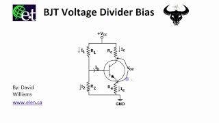


There should be 47kOhms instead of 14k in V_th. (Even thought 2.13V is all right)
The strange part is that despite that, he wrote the Vth value correctly :)
I figured that out as well. I was confused at first. Now i started looking in the comment section if someone pointed it out too. Your comment should be on top so someone doesnt go thru the confusion like me again haha.
Thanks, however I would appreciate seeing this from the design point of view. IE: Given a requirement, create a biased transistor circuit to solve it. I always feel like I've jumped into the deep end when I watch your stuff ;)
I find this with alot of stuff I want to learn about. They explain it from the wrong angle working backwards with the thing we want to know how to do already done - annoys the hell out of me.
@@RavenLuni yes you are true.. We need to know can we set this values from the begining? I need to know how to give values for R1 , R1, RC and RE
I have seen al ot of tut assume a value for ICq and VE= from 1 to 2v and make Vce= half of the VCC
Some Tut assume the value of ICq and given the value of VCC and then you get Vce = VCC/2 and calculate (re) the emiiter internal resistance of the transistor
there are so many ways to design class A CE amplifier from the begining
Please 6.25mA × 100 will give you 625mA for the Ic but you have written 0.625mA
Please I'm a little bit confused there
Keep on going no one teaches with such a patience and with that much theoretical explanation
If you have an EE background you learned Thevenin. For everyone else (hobbyists), most never took formal courses that taught Thevenin.
So although I'm in the EE camp, I taught STEM courses for 5 years at UC Santa Cruz and always sought to empower ALL students, including those who may not have had all the prerequisites for the course.
You did a fantastic job by addressing both audiences (practitioners and hobbyists) in one video, and it's fantastic to find this pro attitude about presenting STEM subjects to as broad an audience as possible, since very few authors do it.
.
Thanks -- good review/test prep for my upcoming Elec 102 final :-)
Why did you divide by (10+2.2) to find Ic(sat)?
sir in 2:45
where did you get the 1.43 v ??
So given that voltage divider we get Vth in terms of Vcc but can we also say Vth=Vb? What I don’t understand is Vb is after we subtract Ib x Rth from Vth but after the voltage divider there’s nothing else there so the voltage at that point between the two resistors isn’t really Vb?
Vth is not Vb, it's Vth - (IB)(Rth) as you suspected it might be. That thevenin circuit is just an electrical equivalent of the circuit. It is not meant to be a physical representation.
At 2:45, did you say micro Amps or Ohms?
Sir thanks simple ande nece electronics info
Thanks a lot man. Saved my ass for the exams
Well done, thanks. Method 2: what for the resistence seen f from the base node to the right is (beta +1) RE?
I think we take that from KCL (kirchov current law) where Ie=Ib+Ic and Ic=(beta)Ib and if we combite we get Ie=Ib+Ib(beta) and Ie=(beta+1)Ib
can we use voltage divider bias as a switch?
muy bueno
thanks!
gnarly
great
Thanks!
What happens with a PNP transistor ?
This is NPN
Where did 0.7V come from
Your ass, lmao
from diode . Vbe =0.7
Sir can i ask why Vth=Ib(6.24k)-0.7-Ie(2.2k) but not =Ib(6.24k)-0.7-Ib(2.2k)
Because you first take I_e * Resistance (Thats the voltage on emitter). Then you convert I_e to I_b*(1+Beta) thus getting 222.2k*I_b instead of 2.2k*I_e (You need only one unknown number to calculate that equation)