That’s a Gem if I came across something like that in an estate sale I would snatch that up in a heartbeat, even though I’m not a antique radio connoisseur I know good stuff when I see it. That’s a keeper . I would play that daily. My mom who is 80 would love it. It has big Diles nothing digital.
The instant warm up is due to the tubes having Directly Heated Cathodes. In order to allow the tube filaments to operate from AC power, an Indirectly Heated Cathode was developed. The Directly Heat Cathode places the filament in a metal sleeve to isolate the filament power from the RF or audio signal. Since the filament is electrically isolated from the Cathode sleeve, it takes the filament some time (about 20 seconds) to heat up the Cathode sleeve before enough electrons start to boil off the sleeve, enabling operation.
Thanks Rick for showing the Atwater-Kent model 10 in operation using a horn speaker (which have a narrow frequency response, barely passing voice frequencies), which was the norm in that day. This was considered a modern set in its day, prior to this model, radios were seperate circuits: RF, Audio, and Power Supply (which were batteries in that day). Since the 3 tuning dials were non-synchronized, a pad of paper was always kept next to the radio to jot down the settings of the knobs for each radio station. The list was arranged for day time and night time stations, each recorded station showed the knob settings, station call letters, and the station city name. The selector switch (upper left) was used to maximize the radio's sensitivity based upon the antenna being used. The longer the antenna, the lower the tap point on the input coil. In practice, you would change the switch position to fine the loudest signal. I was a bit surprised I did not hear one of the RF amplifiers break into oscillation while being tuned. Due to the high capacitance between the vacuum tube grid and plate in a triode, when a tuned circuit is connected to the input and output, oscillation always occurs when the tuning dials are peaked. In looking at the circuit later, I discovered Atwater-Kent inserted a grid resistor (about 600 ohms) in each tunable stage to de-que the circuit, which stops the oscillation at the expense of gain. In that day (mid 1920's), typically all of the tubes used in the radio were the same type; usually 01A tubes. A 6 volt lead-acid car battery was used to run the filaments. 22.5, 45, and 90 volt carbon-zinc batteries were used to supply the remaining voltages for the radio. The carbon-zinc batteries were expensive because they were not rechargable. A 90 volt battery consisted of 60, 1.5 volt carbon-zinc batteries in series. Lead-acid batteries were not well liked in practice, invariably some acid would spill or belch from the battery. The acid would burn holes in the carpet and rust iron and steel. So, in 1926, the breakthroughs everyone was waiting for finally came true: (1) Radios that ran off AC power and (2) Radios using a single tuning knob. At first the tuning knob dial was calibrated 0 to 100 but, it quickly was figured out to better use Frequency (in kilocycles) instead.
You may be interested in my last video on this radio. !923 Vacuum Tube, Amplitude Modulation Detector Circuit in Detail ua-cam.com/video/e0faax3Svgw/v-deo.html
Thanks for showing! This is my favorite of yours yet. My grandfather was born in 1923. He's no longer with us, but it's pretty cool to see something from that time period. I do have an Atwater Kent model 20 from 1926. I didn't buy it new. It's missing the knob on the far right.
Hope you can find the knob for your AK 20. I did tow videos of Ed Bell’s radio collection. I’m lade I did that now! Back to Ed Bell's, the good stuff! ua-cam.com/video/i3-qlAI2GM4/v-deo.html Ed Bell, Radio Collection ua-cam.com/video/CLmjFstqQus/v-deo.html
What a lovely radio and an excellent presentation and tutelage. I was always curious how one tuned early radios with all those separate variable capacitors. If only there were anything worth hearing anymore on the am band...
I almost picked up a Model 40 at an estate sale that they had $15 on last year. That was before we moved and I really didn't have the space. It was complete and in very good shape. I would had excused the missing speaker because they didn't come with one from the factory.
Working as it did the day it was made. Incredible. Could you please explain in one of your future video's the meaning of the word tank as in a tank circuit. As I am now retired i have taken an interest in vintage radio, and living in the UK it's a term I am not familiar with. I so much enjoy your and other radio videos and am learning all the time. Many thanks. Terry
Hi Terry, I'm not sure where the name "Tank Circuit" originated but, was used widely in the US when I was in school in the early 1970's. The circuit is also called a resonator, pole, L/C resonant circuit, and probably a few more names. This circuit is the heart of an L/C filter. The coil or inductor is electrically a mirror image of a capacitor. When the coil and capacitor are connected in parallel, at a certain frequency (as determined by the coil and capacitor value), the reactance of the coil will cancel out the reactance of the capacitor and vice-versa. The point of cancelation is called Resonance. When resonance occurs, the parallel connected coil and capacitor electrically become an open circuit, which allows incoming frequencies that are at the resonant frequency to pass through. So, the Tank Circuit contributed to making radio possible, so that one radio station at a time can be tuned in.
Hello from Tasmania. I see you have a Tek 465 there on your bench and I wonder if I could respectfully ask you to go along the grids and anodes of the Atwater Kent and show us the wavefirms. I realize that the impedances in these old TRF sets is very high and the 1M scope probe will probably load the grid circuits down and not give true readings but you could use x10 probe attenuation in the later stages where the signal amplitudes are greater. I would be fascinated to see what sort of eaveforms appear when the Atwater Kent is tuned into a strong local vs weak DX station. DC voltages under no signal vs strong signal on the filanments, grids and anodes would be also quite reveahling and show these at the resprctive nodes on the circuit. These old 1920’s TRF battery sets are far rarer here in Australia than they are in the United States, so it is very difficult to procure such a set locally to go over with my own scop and VTVM.
Thanks. The waveform is what the station produces, amplitude mediated signal. And a weak station is just less of it. I’l be happy to put a oscope on a 1920s radio to show these waveforms. But not the breadboard, because the TUBE ISLANDS are filled with TAR. They did that a lot in the 1920s. I have other 1920s radio that gives me much easier access to the circuits. Keep experimenting.
@@AllAmericanFiveRadio Thanks for the reply. I did not realize the bottom of the chassis was bogged up with tar but that was a popular material in the era before plastics! I have one 1920’s set here, it is a homebrew very early superhet….I believe that they were made as homebrew kits to avoid patent infringment. It is amazing just how much patent litigation held the technology back in the ‘20’s and juw the technology took off in the ‘30’s once all thet litegous hoo-ha ended! My superhet uses UV-201’s and the I.F. Transformers use bundles of iron wire as open cores….long before ferrite was adapted to this purpose. I can’t run the set because one of the tuning capacitors has a die-cast frame that has all swolenand cracked and fallen to bits. I do have a mire modern electrically equivalent capacitor I could botch into the circuit just for a test, but I will hopefully get around to recasting the frame of the original one day. What fascinates me most about these early sets is the sheer high impedances of it all…a bit too much load and your signal dissappears. I would be fascinated too see what happens if you gat a 1M resistor in series with a 10nF capacitor and connect one wnd of this to ground B- and then use the other end as a probe to probe the point in the circuit where the oscilloscope probe is hooked and see what effect the extra 1M of loading has. After decades of working on semiconductor stuff, I have developed that “low source impedance” mindset that is sometimes hard to break when going back to 1960’s valve gear….let alone 1920’s bright emitting, directly heated valve gear. I and I think thst this is an important point someone in your position and with your lifetime of understanding could be made to all us “young-uns” out here. I recall putting my finger…just near, not actually touching …the grid cap of s 6G8G duo-diode pentode detector-first AF in a 1940,s set and hearing the mains hum on my body be conducted across the few tens of fento-farads between my finger tip and the control grid cap. This is something that semiconductor guys rarely ever experience!
@@thanhhuynh272 The bread board is open on the bottom. But the grid link resistor and capacitor, The RF bypass capacitor, along with both audio transformers are all in the three tube island. The three tube island is filled with tar.
A wonderful set to own & thanks for the clear description. One thing puzzles me. I always thought that multiple tuned circuits were troubled with oscillation & I've always experienced this when constructing such radios using triodes. As I understood it, this problem was solved by 'neutrodyne' circuits & later by screen grid tubes. How did they solve the problem of oscillation in this circuit please?
Thank you. Take a look at the bread board configuration. The antenna coil is mounted on the board vertically. The middle coil is orientated North South, and the left coil is orientated West East. And the coils are fairly far apart. This is what keeps the radio from oscillating. Thanks for the question.
@@AllAmericanFiveRadio Thank you for your reply. Interesting & simple solution. I'd guess those filament rheostats have something to do with it too. They fell out of favour in UK radios when dull emitters became the norm. I've not used them in any of my experimental circuits.
Thank you. I did a more detailed video on the detector circuit, you maybe interested. !923 Vacuum Tube, Amplitude Modulation Detector Circuit in Detail ua-cam.com/video/e0faax3Svgw/v-deo.html @@user-vg9np3gw3k
Ok I watched again grid leak cap and resistor create a high impedance to make grid filament a diode if I understand it right, so the preceding tube grids would be low impedance right, it's normal for plate side of tube to be high z right?
I did a more in depth video on just the detector circuit. !923 Vacuum Tube, Amplitude Modulation Detector Circuit in Detail ua-cam.com/video/e0faax3Svgw/v-deo.html


Haven't seen you for quite a while Richard. I have your book and try to view all your videos. You're an antique radio treasure!
Thank You!
That’s a Gem if I came across something like that in an estate sale I would snatch that up in a heartbeat, even though I’m not a antique radio connoisseur I know good stuff when I see it.
That’s a keeper .
I would play that daily. My mom who is 80 would love it. It has big Diles nothing digital.
Thank you!
I'd want it to honor my dad's birth year, but there's no way I could afford one.
Rick - that radio is a national treasure. I was so surprised there was no warm up needed.. it came up right away !
Thank you. 5 Volt tube warm up quickly.
The instant warm up is due to the tubes having Directly Heated Cathodes. In order to allow the tube filaments to operate from AC power, an Indirectly Heated Cathode was developed. The Directly Heat Cathode places the filament in a metal sleeve to isolate the filament power from the RF or audio signal. Since the filament is electrically isolated from the Cathode sleeve, it takes the filament some time (about 20 seconds) to heat up the Cathode sleeve before enough electrons start to boil off the sleeve, enabling operation.
@@billharris6886 That and 0.25 AMP @ 5VDC for the filament
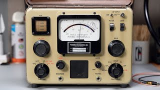
Thanks Rick for showing the Atwater-Kent model 10 in operation using a horn speaker (which have a narrow frequency response, barely passing voice frequencies), which was the norm in that day. This was considered a modern set in its day, prior to this model, radios were seperate circuits: RF, Audio, and Power Supply (which were batteries in that day). Since the 3 tuning dials were non-synchronized, a pad of paper was always kept next to the radio to jot down the settings of the knobs for each radio station. The list was arranged for day time and night time stations, each recorded station showed the knob settings, station call letters, and the station city name.
The selector switch (upper left) was used to maximize the radio's sensitivity based upon the antenna being used. The longer the antenna, the lower the tap point on the input coil. In practice, you would change the switch position to fine the loudest signal.
I was a bit surprised I did not hear one of the RF amplifiers break into oscillation while being tuned. Due to the high capacitance between the vacuum tube grid and plate in a triode, when a tuned circuit is connected to the input and output, oscillation always occurs when the tuning dials are peaked. In looking at the circuit later, I discovered Atwater-Kent inserted a grid resistor (about 600 ohms) in each tunable stage to de-que the circuit, which stops the oscillation at the expense of gain.
In that day (mid 1920's), typically all of the tubes used in the radio were the same type; usually 01A tubes. A 6 volt lead-acid car battery was used to run the filaments. 22.5, 45, and 90 volt carbon-zinc batteries were used to supply the remaining voltages for the radio. The carbon-zinc batteries were expensive because they were not rechargable. A 90 volt battery consisted of 60, 1.5 volt carbon-zinc batteries in series. Lead-acid batteries were not well liked in practice, invariably some acid would spill or belch from the battery. The acid would burn holes in the carpet and rust iron and steel. So, in 1926, the breakthroughs everyone was waiting for finally came true: (1) Radios that ran off AC power and (2) Radios using a single tuning knob. At first the tuning knob dial was calibrated 0 to 100 but, it quickly was figured out to better use Frequency (in kilocycles) instead.
You may be interested in my last video on this radio.
!923 Vacuum Tube, Amplitude Modulation Detector Circuit in Detail
ua-cam.com/video/e0faax3Svgw/v-deo.html
@@AllAmericanFiveRadio Okay thanks, I will check it out!
Thanks for showing! This is my favorite of yours yet. My grandfather was born in 1923. He's no longer with us, but it's pretty cool to see something from that time period. I do have an Atwater Kent model 20 from 1926. I didn't buy it new. It's missing the knob on the far right.
Hope you can find the knob for your AK 20.
I did tow videos of Ed Bell’s radio collection. I’m lade I did that now!
Back to Ed Bell's, the good stuff!
ua-cam.com/video/i3-qlAI2GM4/v-deo.html
Ed Bell, Radio Collection
ua-cam.com/video/CLmjFstqQus/v-deo.html
Another great one Rick!! 100 years? Just broken in.
Yes it is.THANK YOU!
Very nice AK10, Rick! Thanks for sharing! Take Care-Larry
Thank you, and your welcome.
Love those bread board radios. Thanks for sharing and educating all of us.
Thank you!
Fantastic !👍👍👍
Thank you, and your welcome.
Very cool piece of history! Thank you for sharing and demonstrating it!
Thank you, and your welcome.
Amazing, very nice explanation. Thank you
Thank you, and your welcome.
Very nteresting thaks you for showing the early tube radio . I personnaly star with AR5 BC receiver thta was mount on B29 . See you thanks !!
Thank you, and your welcome.
Cool!!!!! I've never seen how you tune one of these old non het sets. Great explanation at the end too.
Thanks.
Can you imagine the original owners 100 years ago tuning in stations at night. That had to be amazing.
Very timely as I have one partly restored. Thanks!
Thanks, hope you get your AK working. Let me know what happens.
What a lovely radio and an excellent presentation and tutelage. I was always curious how one tuned early radios with all those separate variable capacitors. If only there were anything worth hearing anymore on the am band...
Thank you. We have an oldies station 850. You did hear a little of it. Could not leave the radio on 850 because of copyright infringement.
Amazing! Really glad we don't have to tune our radios that way any more.
Thank you.
I almost picked up a Model 40 at an estate sale that they had $15 on last year. That was before we moved and I really didn't have the space. It was complete and in very good shape. I would had excused the missing speaker because they didn't come with one from the factory.
Thanks, hope you find one.
Working as it did the day it was made. Incredible. Could you please explain in one of your future video's the meaning of the word tank as in a tank circuit. As I am now retired i have taken an interest in vintage radio, and living in the UK it's a term I am not familiar with. I so much enjoy your and other radio videos and am learning all the time. Many thanks. Terry
Thanks, good idea.
Hi Terry, I'm not sure where the name "Tank Circuit" originated but, was used widely in the US when I was in school in the early 1970's. The circuit is also called a resonator, pole, L/C resonant circuit, and probably a few more names. This circuit is the heart of an L/C filter. The coil or inductor is electrically a mirror image of a capacitor. When the coil and capacitor are connected in parallel, at a certain frequency (as determined by the coil and capacitor value), the reactance of the coil will cancel out the reactance of the capacitor and vice-versa. The point of cancelation is called Resonance. When resonance occurs, the parallel connected coil and capacitor electrically become an open circuit, which allows incoming frequencies that are at the resonant frequency to pass through. So, the Tank Circuit contributed to making radio possible, so that one radio station at a time can be tuned in.
Hello from Tasmania.
I see you have a Tek 465 there on your bench and I wonder if I could respectfully ask you to go along the grids and anodes of the Atwater Kent and show us the wavefirms.
I realize that the impedances in these old TRF sets is very high and the 1M scope probe will probably load the grid circuits down and not give true readings but you could use x10 probe attenuation in the later stages where the signal amplitudes are greater.
I would be fascinated to see what sort of eaveforms appear when the Atwater Kent is tuned into a strong local vs weak DX station.
DC voltages under no signal vs strong signal on the filanments, grids and anodes would be also quite reveahling and show these at the resprctive nodes on the circuit.
These old 1920’s TRF battery sets are far rarer here in Australia than they are in the United States, so it is very difficult to procure such a set locally to go over with my own scop and VTVM.
Thanks.
The waveform is what the station produces, amplitude mediated signal. And a weak station is just less of it. I’l be happy to put a oscope on a 1920s radio to show these waveforms. But not the breadboard, because the TUBE ISLANDS are filled with TAR. They did that a lot in the 1920s. I have other 1920s radio that gives me much easier access to the circuits. Keep experimenting.
@@AllAmericanFiveRadio Thanks for the reply. I did not realize the bottom of the chassis was bogged up with tar but that was a popular material in the era before plastics! I have one 1920’s set here, it is a homebrew very early superhet….I believe that they were made as homebrew kits to avoid patent infringment. It is amazing just how much patent litigation held the technology back in the ‘20’s and juw the technology took off in the ‘30’s once all thet litegous hoo-ha ended! My superhet uses UV-201’s and the I.F. Transformers use bundles of iron wire as open cores….long before ferrite was adapted to this purpose.
I can’t run the set because one of the tuning capacitors has a die-cast frame that has all swolenand cracked and fallen to bits.
I do have a mire modern electrically equivalent capacitor I could botch into the circuit just for a test, but I will hopefully get around to recasting the frame of the original one day.
What fascinates me most about these early sets is the sheer high impedances of it all…a bit too much load and your signal dissappears. I would be fascinated too see what happens if you gat a 1M resistor in series with a 10nF capacitor and connect one wnd of this to ground B- and then use the other end as a probe to probe the point in the circuit where the oscilloscope probe is hooked and see what effect the extra 1M of loading has. After decades of working on semiconductor stuff, I have developed that “low source impedance” mindset that is sometimes hard to break when going back to 1960’s valve gear….let alone 1920’s bright emitting, directly heated valve gear. I and I think thst this is an important point someone in your position and with your lifetime of understanding could be made to all us “young-uns” out here. I recall putting my finger…just near, not actually touching …the grid cap of s 6G8G duo-diode pentode detector-first AF in a 1940,s set and hearing the mains hum on my body be conducted across the few tens of fento-farads between my finger tip and the control grid cap. This is something that semiconductor guys rarely ever experience!
@@thanhhuynh272 The bread board is open on the bottom. But the grid link resistor and capacitor, The RF bypass capacitor, along with both audio transformers are all in the three tube island. The three tube island is filled with tar.
A wonderful set to own & thanks for the clear description. One thing puzzles me. I always thought that multiple tuned circuits were troubled with oscillation & I've always experienced this when constructing such radios using triodes. As I understood it, this problem was solved by 'neutrodyne' circuits & later by screen grid tubes. How did they solve the problem of oscillation in this circuit please?
Thank you. Take a look at the bread board configuration. The antenna coil is mounted on the board vertically. The middle coil is orientated North South, and the left coil is orientated West East. And the coils are fairly far apart. This is what keeps the radio from oscillating. Thanks for the question.
@@AllAmericanFiveRadio Thank you for your reply. Interesting & simple solution. I'd guess those filament rheostats have something to do with it too. They fell out of favour in UK radios when dull emitters became the norm. I've not used them in any of my experimental circuits.
@@tiga4180 Keep experimenting!
@@AllAmericanFiveRadio Will do!
Excellent question, Paul.
❤❤❤
Thank you, and your welcome.
@@AllAmericanFiveRadio thank you for your kindness 🙏
Thank you. I did a more detailed video on the detector circuit, you maybe interested.
!923 Vacuum Tube, Amplitude Modulation Detector Circuit in Detail
ua-cam.com/video/e0faax3Svgw/v-deo.html
@@user-vg9np3gw3k
@@AllAmericanFiveRadio yes please I need also for model 12 🌹🙏
@@user-vg9np3gw3k It is the same as a model 10, but it has one more audio stage. Six tubes.
www.nostalgiaair.org/PagesByModel/384/M0039384.pdf
I'd like to understand how that detector circuit is acting like a diode between grid and filament?
Thanks, good idea.
Why does the detector tube grid filament, act as a diode, and not the preceding tubes?
Ok I watched again grid leak cap and resistor create a high impedance to make grid filament a diode if I understand it right, so the preceding tube grids would be low impedance right, it's normal for plate side of tube to be high z right?
I did a more in depth video on just the detector circuit.
!923 Vacuum Tube, Amplitude Modulation Detector Circuit in Detail
ua-cam.com/video/e0faax3Svgw/v-deo.html
How much is that set of tubes worth?
Used $19-$30 each
New NOS $70-$80 each