Nice video! This is supplemental to your website? Would like more info regarding your "Amplifier Classes: A, B, C, D, etc" page trying to understand the "Conduction Angle Θ" you have for Class AB
Thanks - glad you appreciated the video. Yes, the video channel and website are both mine. I’ll take a look at your suggestion about improving the amplifier classes page. Thanks for the suggestion. It might not happen immediately because there are a few other projects happening at the moment.
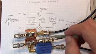
Yes, RFC stands for radio Frequency Choke. As mentioned by another it is an inductor intended to block the radio frequency signals as it is a high impedance at RF and low impedance for DC. In this circuit is allows the correct bias conditions for the amplifier while not dissipating any of the RF signal.
We only ever intended it to be a primer. The number of people who would want real in-depth technical details are relatively small and it would end up making the video too long. On top of this it would have taken more than the 10 - 15 man days it took to make the existing one. I hope that you were not too disappointed with it.


Very cool! Something like a high-speed AGC feedback loop for RF Power MOSFETs
Very cool indeed - development of the techniques was not easy, but it saves a lot of power in mobile phones and many other circuits & situations.
Thank you for taking time and making very detailed video
Glad you found it useful.
Nice video! This is supplemental to your website? Would like more info regarding your "Amplifier Classes: A, B, C, D, etc" page trying to understand the "Conduction Angle Θ" you have for Class AB
Thanks - glad you appreciated the video.
Yes, the video channel and website are both mine. I’ll take a look at your suggestion about improving the amplifier classes page. Thanks for the suggestion. It might not happen immediately because there are a few other projects happening at the moment.
Best exploration sir.... Thank you so much
Glad the video was useful. Thanks.
Thanks for this. Wonderful video.
I'm glad you found it useful.
Sorry I am a power electronics engineer and do not know RF systems! What is RFC at 0:20?
This is a dividing line
inductor coil.
Yes, RFC stands for radio Frequency Choke. As mentioned by another it is an inductor intended to block the radio frequency signals as it is a high impedance at RF and low impedance for DC. In this circuit is allows the correct bias conditions for the amplifier while not dissipating any of the RF signal.
Brilliant video, crisp and clear, thank-you!
Im really glad it was helpful!
Excellent! very clear explanation, even to a stupid guy like me
Thanks for the comment . . . and I wouldn't think you are stupid at all.
Thanks a lot!
I'm glad the video was useful.
👍
Thanks.
Ok as a primer but pretty superficial on technical details
We only ever intended it to be a primer. The number of people who would want real in-depth technical details are relatively small and it would end up making the video too long. On top of this it would have taken more than the 10 - 15 man days it took to make the existing one. I hope that you were not too disappointed with it.
@@ElectronicsNotes No it's pretty good. I don't know what the point of these comments is. Of course it's not a freaking lecture