
Вставка
- Опубліковано 7 чер 2024
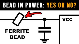
- Why? It helps with power noise filtering, easy to measure currents, circuit can be disconnected, …
Would you like to support me in what I do? It's simple:
- sign up for one of our Schematic and PCB Design online courses at www.fedevel.com/academy/
- support me through Patreon page / robertferanec
- sign up for my Udemy course, Learn to Design Your Own Boards
www.udemy.com/learn-to-design...
Or:
- send me an email and/or leave a positive comment
- watch and like the videos :)
- read my Welldone Blog at www.fedevel.com/welldoneblog/
- spread a word about FEDEVEL Academy
It is much appreciated.
- Robert


Great design tip! Please keep them coming Robert.
Great job! Great Tips!
Thank you Robert
Great tip Robert. Thanks!
great tips. thank you
Thank you for this great tip.
Hi, I think Dr. Eric Bogatin has some unique perspectives on this design, could you please invite him to talk on the bead design in power network?
very nice.. thanks master
Hopefully you’ve “gotten power delivery religion” now, based on your more recent videos, which reveal that FBs in series with power rails for digital chips in particular is a pretty bad idea. perhaps you should add an overlay message on this video saying “it’s wrong, and so are most datasheets & app notes that recommend it, and watch my newer videos on this topic to learn why!”
according to my info zero resistors are used for test purposes or to make designed pcb more flexible for future adjustments. It can not work as a filter unless it is changed to a real non zero value. we all know that the cut off frequency for low pass filters is f=1/(2xPixRC) so if R=0 >> f= infinity that means no filtering. Please correct me if I am wrong.
They have none-zero resistance and also some inductance, but I'd guess they're just there to leave space for adding a bead if needed later, or for other rework on the power line.
Thank you for the video!!! If i use sensor like bme680 or dac, adc mcp4725, mcp3425 - do I need add FERRITE ? when modul small like adafruit or sparkfun? Or i need use ferrite only for microcontroller or microprocessor. Thank you!
Usually I place ferrite bead:
- before a component / pin which may generate noise back to the power rail,
- before a component / pin which may be sensitive to noise on power rail,
- to separate main power rail from a local power plane
- on components where I would like to have option to measure or disconnect power
So to answer your question directly, usually for components like sensors, I do not use ferrite, they are usually conencted directly to the big power plane, for ADC I may use ferrite (or I use LDO regulator, depends how sensitive AD is), for DAC I may want to use it. If the module is very small, beads may not be necessary, but I would be using some kind of filtering anyway.
As I know, ferrite beads have different resistance values. What range of resistance of ferrite bead is appropriate for applications that uses lower than +3V3 as power source voltage? Is there any criteria or guide that you know to select best resistance value for ferrite beads?
Normally the simplest way is to use the same / similar bead as in reference board. Sometimes we minimize number of different beads in the design by using same beads as used in the most critical part of the schematic.
Ideally you may want to go to a bead manufacturer website and they have some recommendations or calculators - that can be specific for the circuit you are using. I am not sure if there are some really generic recommendations.
I am really full totally and completely confused about the connection between 0R and ferrite bead, ferrite beads are used to filter high frequency noise since they dissipate the high frequency signal as heat while the 0R resistor is basically supposed to be a short. What is the relationship?
Based on its construction, does 0R SMD resistors improve on noise reduction as well?
yes I am confused about this
How can resistor filter signals?
Is this still as important on battery powered applications?
Please did you ever find out
Hi robert great tip, but I have a serious doubt. I usually see microchip products use 100 to 220 ohms Impedance @100MHz specified ferrite bead. But what happens if we use a 33Ohms @ 100MHz ferrite bead? How do I choose a ferrite bead? What effects will be there? Please do answer this question. Thanks a lot
I would be now more careful about using ferrite beads. This video can be interesting for you: ua-cam.com/video/hZSOhVdzqZk/v-deo.html
I personally quite often use small 2r2 or 4r7 resistors (even with ferrite beats). Not only for the noise but also as a cheap fuse.
What should be the value or model of the farrite beads here....
I usually use the BEADs from reference schematic or I use the BEADs what we use on different projects (so we have them in stock). Important is current rating - be sure the BEAD can handle the current. If you would like to calculate BEAD values more properly, the BEAD manufacturers have some tools for it, e.g. www.murata.com/support/faqs/products/emc/emifil/use/0010
so n LC filter?
If there is no recommendations made how do we choose the values for ferrite and the caps?
ilkay C you need to take in consideration the main frequency of the noise in the power rail, if you are using fixed frequency switching for instance, you want to filter that out.
If using LDOs, most specify a maximum capacitive load, so don't over do it.
Also be careful with startup time, loading a line with too much capacitance will slow down the startup.
My general rule when in doubt, is to always place more than you need when designing your board, since you can always not mount them, while capacitor stacking is pretty much impossible in production.
thank you Xavi
Ferrite beads suppress HF noise may go into your circuit
This is also making your power plane completely unnecessary. You could use wide traces for instance and decrease amount of layers.