How Low Pass Filters Work

Вставка
- Опубліковано 2 жов 2021
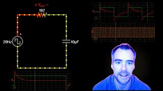
- This video gives visual demonstrations of how capacitors and low pass filters work. It shows the circuit, the equations, the time-varying inputs and outputs, and the frequency response plot.
Start with visual of capacitor and current and voltage and time
Show applied DC voltage and voltage across capacitor
Note current initially flows until capacitor 'charges up' to source voltage level
Capacitor discharge in same time
Note that increasing capacitance makes it take longer to charge
Increased capacitance corresponds to decreased impedance per the equation
Which means it's not 'impeding' as much on stopping the current from flowing through it.
Discuss connection between temporal response and cutoff frequency
Go back to 10 u
Now instead of a DC input hear let's go with a square wave with 20 Hz
This is going to cycle between 5 V to -5 V 20 times a second, so one cycle every 50 ms.
Notice the voltage across the capacitor takes a little bit of time to follow this, but it catches up and is the same as the square wave most of the time
That means this signal at a frequency of 20 Hz would 'pass'.
Now let's crank this up to 85 Hz, which happens to be the cutoff frequency of this filter.
Notice that as soon as the capacitor 'catches up' to the source voltage, it gets switched. So at this frequency, the source signal might pass, but it will be attenuated since the voltage across the capacitor is spending most of the time 'catching up' to the changing source
Now let's crank this up to 500 Hz, which is beyond the cutoff frequency.
Now you can see the capacitor voltage never has enough time to 'catch up' with the alternating source voltage. So some of the signal would pass but it would be significantly attenuated
If we crank this up even further to 5 kHz you can see there is basically no response from our output voltage. The 5 kHz input square wave is (almost) completely cutoff.
Now let's visualize what we've shown on a frequency response graph.
So here the x axis represents frequencies in a log scale, and the y axis represents how much of the source signal gets through to the ouput.
So if we go on this graph to the frequency we first showed of 20 Hz, you can see the the loss is small, and this is where our output signal was pretty close to the input signal
Then we go up to 80 hZ and you can see this curve has gone down a bit, this repsresents the -3dB where our output has lost about half the power of the input signal.
Then we go to 500 Hz and you can see it's further down,
And 5 kHz is of course further down still representing more attenuation of our source square wave
So you can see how this setup yields a low-pass filter, because it will pass the lower-frequency 20 Hz signal pretty closely, but will almost completely reject the 5 kHz squarewave.
So this is how a low pass filter works to allow lower frequencies and reject higher frequencies, and as discussed this is due to the time delay capacitors have with storing electrical energy.
If you were able to follow this, then you should have a good fundamental understanding of how capacitors and low pass RC filters work, and if you understand this, then it should be relatively straight forward to extend this understanding to how high-pass filters work, and to how filters using inductors instead of capacitors.


4 years of university study explained in a 8 minute video. Bravo sir!!
@@stefangrozdanovic4908 thanks my man
Best description ever my man
Thanks!
Im trying to understand guitar pedal circuits and this video was incredibly helpful. Thanks!
One of the best explanation.
Matthew, amazing explanation and visualization. Thank you a lot!
Thanks, my pleasure.
thank you for this demonstration
My pleasure.
Very useful visualization and walkthrough, thank you.
Thanks, my pleasure.
Best explanation so far
Really solid and pedagogical content!
thanks!
Fun and instructive.
Amazing video, thank you so much!!!
Thanks. My pleasure.
excellent explanation
very good! thanks
wow very cool
A brilliant video, thanks a lot.
Thank you, my pleasure.
Please consider making one of these for high pass filters as well
Just published one for high pass RC filters, and another for high pass RL filters.
ua-cam.com/video/H30kRgI5bi0/v-deo.html
ua-cam.com/video/nDgMSehurtQ/v-deo.html
Very informative, thank you
Glad you found it informative, my pleasure.
Wow, good job!
Thanks, my pleasure.
nice
Thanks for sharing, amazing video for explaining LPF.
Just curious, cut-off frequency should be the point at -3dB not the point at the critical point of 0dB.
In -3dB, Po/Pin = 1/2, that Vo/Vin = 0.707.
So red curve=Vo, Vo/Vin=(1 - e^(t/RC)) ramp-up to about 0.707 while being cross the green square pulse(Vin). That’s what I think of it but not pretty sure correct or not. Just for discussion, please correct me if any points I got wrong.
thank you!
My pleasure
Great explaination! Additionaly it would have been interesting to change the value of the resistor.
My question I ask myself is: which frequency should I set the filter for a DC Signal to filter out noise on the ADC input of my esp8266. Can it be too low? Ist it better to use a big resistor or a big capacitor to get a specific frequency?
Or you can have a mosfet acting as a switch right?
Hello thank you for the great information. İs it possible to learn the software that you use?
Hi, thanks for the comment. This is an online application you can use here:
www.falstad.com/circuit/e-index.html
I think the simulation I used was under the 'Passive Filters' heading on that website.
It was really useful. Can you make one using an Op-Amp too?
Thanks, can't make new videos for a while though unfortunately. Too busy with new job.
which software are you using for making circuits
falstad.com
it's great
hi Matthew, thanks for your video, I would like to know why is -3dB for cut off frequency?
Hi. -3dB is just the standard used for filter cutoff values because it is the 'half power' point. It corresponds to a sqrt(2)/2 or, .707 decrease in voltage, but power is proportional to voltage squared. So if you square .707 you get 0.5. So for example, let's assume R is a constant 1 Ω.
Lets say you have a signal at 5 V, its power would then be (5 V)^2 / (1 Ω) = 25 W
.
Now if it went through a filter at the -3dB cutoff frequency, the output voltage would be , (5V⋅(2√2)) = 3.54 V
And the power would be , (3.54 V)^2/ (1 Ω)= 12.5 W, which is half of the signal power of 25 W. Does that make sense?
I'm pretty sure 3dB or half power was picked arbitrarily as a nice round number which allowed for comparison between filters.
Why does the 24VDC power supply act as a low-pass filter circuit?
Hi Ali, not sure what you are referring to by the 24 V DC power supply. Here I used a 5 V AC power supply.
What happens to the filter if you increase the capacitance?
Good question! Increasing the capacitance will slow down the output voltage response as shown around the 2 minute mark. The decreased response time will decrease the cutoff frequency of the low pass filter. So the filter will then cause more attenuation to the signals at higher frequencies.
Why didn’t you use 10 µF? I thought that was the value of C. Instead you wrote 10 x 10^-6 s/n
I don’t get how you got that from 10 µF
I should have mentioned that, but one Farad is equivalent to 1 second/Ohm. I used the s/Ohm to show that the Ohms would cancel out in the equation.
How capacitor is discharged when low inputs we provide
I'm not sure what you mean. At the start of the video you can see how the capacitor is discharged when connected to a circuit with just a resistor.
I think you demo would be better illustrated using a sine wave instead of a square wave. WIthout the extra high frequency content of the square wave, your 20Hz signal would pretty much match, which I think would be more intuitive.
You're correct a sine wave would match better at 20 Hz. Personally the square wave is more intuitive for me though because it shows there is still some imperfection in response based on how the RC voltage and current flow.
I found an old printer next to the trash and I wanted to open it and remove the circuit elements... When it was time for the capacitor, all of a sudden there was an electric shock and it really hurt me 🤣. Make sure the capacitors are completely discharged when removing elements from the circuit board.😉
Yikes. But yeah that makes sense if the capacitor had a charge stored on it then your hand completed the circuit the current discharged through.
Why does a power supply act as a low capacitor?
An ideal power supply itself doesn't act as a capacitor, it just supplies the voltage or current.
smart people should ask this in low pass filter in order to understand why his explantion is wrong* :
1. the capcitor is fully charged when the input frequency is low like 20hz, ok and simple to understand, nothing complex...
then
2. when frequency input is very high like 500hz then the capcitor just dont fully charged but way less because of the speed of the input frequency...mean the capacitor start to charge him self and suddnely the source go off state, hence not fully charged, in different words....
which mean according to his explantion in the first situation the capcitor is fully charged and in the second example the capcitor is just dont fully charged lets say half.....ok up to this point everything is simple to understand...here the problem comes....
then someone smart ask but hi, the frequency stay the same its just the capcitor dont charged fully and the output of the capcitor also the same charge he charged...
then how the hell its filter high frequencies ??????
low pass filter mean this...for example the input is 1000 hertz(1khz) mean 1000 cycles per second and after it pass the circut its 200 hertz, mean 200 cycles per second, mean less cycles per second...which mean ......that the capcitor dont charged every time but miss alot of the cycles and hence the output its lower frequency...other wise according to his explantion you dont filter out frequencies...but just output half the input, but frequency is the same
Attenuate 🤡👉🏽💨
Not sure what you are referring to.
Why does the power supply act as a low-pass filter circuit?
An ideal power supply itself doesn't act as a low-pass filter, it just supplies the voltage or current.
Does current stop passing after capacitor gets fully charged?