The 555 Timer In Monostable Mode Brought to you by Solderstick wire connectors

Вставка
- Опубліковано 4 жов 2024
- The 555 Timer In Monostable Mode Brought to you by Solderstick wire connectors
Get solderstick at 20% OFF with discount code "LE20" at www.solderstic...
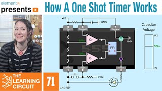
In this video we look at one of the ways in which a 555 timer may be configured. This method is known as the "monostable" or "one-shot" mode. The 555 will output a pulse for a specific time determined by the R and C components. The formula for determining the pulse length is 1.1*R*C. - Наука та технологія


this circuit became a great night light, with a few simple changes to it, to run a 1w warm white LED via mosfet. 50k pot and 3300uf cap for the timing and 2200uf cap to provide a nice fade out when it turns off. Stays on for up to an hour.
Cool.
Thank you, for the best explanations of the 555 I’ve seen
Glad it was helpful!
Well, that was interesting. I always have timing issues/needs and always solve it with code, never knew that solution for timing things.
Although I have inventory of the old school 555's, and 5556's... including the mistaken misprint of the 5557's, but none the less, my question.. A few years ago, about 10 to 12 years, I read or somebody told me, that the 555 series was discontinued, due to nobody wanting them, and or, a newer version that was a better design replaced it... How true is this... And, what is this "NEW MODEL" of the 555 series 8 pin.. The 4 or 5 models I have found, all seem to have an additional feature that can actually get in my way from some of the projects that the study 555 series would just simply deal with.. Any help would be fantastic from anybody in the chat or the channel owner... Anyhow, another great video.
I'm no expert, but the 555 is quite abundant on the internet.
@@Larry-AK0Z oh yes, I can agree with that. Was just wondering if there was actually a factual moratorium on that series is all...
@@drubradley8821 Is 555 timer still used?
In 1972, the company Signetics announced the NE555 timer IC (integrated circuit). 50 years later, it is still used and is consistently sold in its billions every year.
Good job!
Thanks!
PAUL, can you explain in another video about the formula T= 1.1 x R x C , where does the 1.1 come from?
It's just a constant, like 2562 for measuring running micro farads of capacitors.
Help, i have built this circuit. But when i touch the contacts the lights glows but never turns off😢
Does the timing cap need to be in a certain way because it is polarized? Thank you.
Yes. Stripe to ground.
Is their a way to do it so when it’s power is applied and stays on it runs for x then turns off until the power goes off and comes back on again?
T=1.1… What is 1.1?
It's a coefficient value to help calculate the approximate time of the pulse or cycle. I'm not sure exactly how that number is derived, but it could have something to do with charging times and supply voltages.
It's there because charging occurs between 1/3 and 2/3 Vcc.
Thank you for the question and answer.
It's derived from the discharge of the capacitor C through the resistor R. The voltage difference across the capacitor (which is charged at Vcc at the beginning) is (t=time) V(t)= Vcc * exp(-t/(RC)). When V falls to 1/3 of Vcc the comparator inside the 555 will trigger (then output=0). So you solve for t Vcc* exp(-T/(RC)) = Vcc/3 exp(T/(RC)) = 3 T/(RC) = ln(3) ~1.0986 thus T ~ 1.1 RC.
Oh..no..! Seeing those environmental splices is giving me NALCOMIS flashbacks...😭
Flyboy huh?
1000 micro farad