How a Switching Power Supply Works and How to Make One

Вставка
- Опубліковано 14 жов 2024
- Circuit Link:
electrobuff.bl...
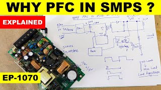
In today's video I'll be showing you how to make a Switching Power Supply with a detailed description about the working of a practical Circuit. It's a simple yet very capable Self-Oscillating Flyback Switch Mode Power Supply which has a Regulated output of 12Volts and a Current capacity of up to 10Amps.
As always, thank you for your time. Don't forget to Like, Share with your friends, check some of my other videos and SUBSCRIBE for more!
#Power Supply #SMPS #electronics
Website:
electrobuff.blogspot.com


Nice video am from Nigeria good morning and good work u did I love it
Good Video explaining everything. Design can be improved. You have R2 = 1K gate drive resistor (make it 10 Ohms) Gate drive is very slow so slow switching wave forms so FET gets HOT so you need to use a HUGE MOSFET IRFP460. The primary current is 0.7/0.22 = 3.2 Amps pk. and the transistor is capable of 20 Amps. Perhaps other improvements but I leave that to you.
I tried your suggestion of making the gate resistor to around 100R. The MOSFET gets burnt. I think you can go as low as 2K to be safe, and not lower.
can u please tell me how the switching frequency and the duty cycle is calculated from the feedback R2 and C6??
@@MrAk962 can u please tell me how the switching frequency and the duty cycle is calculated from the feedback R2 and C6??
@@RanaRao_Chandrachur
No body have actually answered that question since I started asking for the formula for switching frequency and duty cycle. It is sad!
I know many people have been wondering if the circuit works or not. The simple answer is that in its current form "NO" or maybe if you buy a damn powerful mosfet with literal cooling and also way too big transformer for the purpose. But the circuit can work with various modifications and indeed with an EI33 Core if it is balanced at both ends. I have built a working 16V flyback converter inspired by this circuit. If there is anyone who wants to build a 16V AC/DC converter, I can recommend the rebuilt version so you don't have to buy 10 pcs. mosfet which you will otherwise burn.
I wish you could dub the audio again, the audio quality is very poor, your viewers cannot understand what you're talking.
I cannot really follow this video because of bad audio together with talking too fast.
Thank you brother foe this educative video.
Excellent project
wire calibre to use for Tranformer ??
can u please tell me how to calculate the switching frequency and the duty cycle from the feedback R2 and C6??
hallo brother how the MOSFET get the switching frequency can you give me the answer plase
nosotros los hispanoas quedamos gringos amigo,gracias x el video
hi . how to calculate frequency of this circuit?thanks
What changes need for out put 48v 5Amp.
This project is very good!
I know you had the best of intentions but without good audio quality, this is all for nothing. If you could also speak a bit slower it would be very helpful. This was very difficult to comprehend.
ua-cam.com/video/cX4q0e124C4/v-deo.html&ab_channel=DiodeGoneWild
there you go
Yes, not only is he speaking fast and having a strong accent, he was also away from the microphone which was picking up the room echo/reverberation, and made it even worse by saving the audio in a crappy audio compression format at low bitrate settings which made it at least twice as bad and very hard to comprehend. The background music didn't help either, it would have been slightly better and easier to understand without it, but not by much.
At least he tried, so A for effort. What I can't stand is english titles but the video is in a completely different language without subtitles.
You have 12.7V and a 12V zener; the Vf of the ired led inside the opto is 1.2v to 1.4v (?) does it work like that, i guess not
If you wanted to make this adjustable voltage by controlling the pwm, which resistor should you replace with a potentiometer?
On the secodary side you could use TL431 IC or a lower voltage zener instead of D9 (that would be the lowest voltage you could set it to) and use a potentiometer (like 2K value) across the output, with its middle leg (slider) connected to the top (cathode) of the zener. You could also bypass zener in that case and get an even lower voltage (PC817 opto-coupler LED would act as a zener), but I can't guarantee a very stable voltage.
Can you please talk about feasibilty of the circuits you analyzing. Because most of them are not practical and actually not working.
what changes need to be done if we want an output of 36V, 5A.
Plz reply ElectoBUFF
How much frequency for operate this device
bjr S V P je peux avoir les references du transformateur ( 15T/15T/3T &7T ), merci
Very Very helpful 👏 👌 video
hi sir
it's a good work
I want the exact components of this circuit and the process explained by text
Can anyone tell me the range of frequency to drive the MOSFET in the supply
The music needs to go away...i don't understand why there is music.. And the icon at the bottom flashing. Is another distraction... Can't hear your explanation...
Transformer wire size??
can you tell me that which simulation software you used??
Proteus
What is the Frequency of this Diagram
Хорошая схема, сохраню ! Боагодарность
Very good!.
Thank you for your work!
Could you share me the transferfunction of this circuit
Can we charge the battery it.
Jakież szczegóły jak nawinąć transformatory średnica uzwojeń itp itd
what is diameter of transformer wires and core size ?
Por favor si es tan amable si puede presentar un diagrama de una máquina de soldar inverter
Merhaba
Diy 14.4v li ion bms pwm charger make....input and output same connecter ..only 1 in and out pin
Your voice is reverberating and is soft and background music is louder and making it difficult to understand what you are saying, so thumbs down to the back ground music
What is the purpose of c6
Don't mind you are not mentioned transformer Or wir diameters
Please add 50w/36v led driver circuit with ldr facility
what is the need for banckground music in tutorial video. Audio quality is poor
I had a terrible mic
12 v 100 amp please
pdf please to make a pcb?
There is no GDT (not separate), but that's OK
I think optocouplet ic polarity is wrong 🤔
What is the use of C 6
It's part of the positive feedback that goes back to the gate of Q2 through R2.
@@stm3252 can u please tell me how the switching frequency and the duty cycle is calculated from the feedback R2 and C6??
excelente video pero seria bueno que lo subtitularas al español
si señor pero ya esta para los que lo necesiten en español
Make quality audio and speak clearly
Speaking speed is very fast. Unable to understand fully, otherwise good presentation.
Keep playback speed .75X
Please make Indonesian translation because I don't understand English
Its a Diode Gone Wild design!
There's tons of such a Circuit online. I personally tested this on a PCB and it works fine.
Ferrite core number
Not worked because No information about trans is mentioned
don't use background music
audio too poor and fast like train good stuff but not understandable
Your voice is not clear at all, you have a good content, but the audio quality is poor, furthermore, can you speak a little slowly please!
can't understand what you say
Wtf, i try this scematic it's doesnt start, fc
@Sixin3cm naap k can you shar your build pcb photo and data plase
Good but very very poor audio
Pichay jo sound lga rakhi hai usay to band kr lo or Hindi mai he bna lo video to syd jada acha hoga
I cannot really follow this video because of bad audio together with talking too fast.
background music is annoying
Circuit not worked
@Amit Kewat thanks for replying bhai jee
@Sixin3cm naap k brother transformer konsa use kiya hai "ee25 " ?? ya koi dusra or transformer or transformer kha se bnaya
this circuit is not practical, as the power in R1 and R2 is 65W. calculating the power in R1 and R2: (311V ÷ 1470R) × 311v = 75.79W.
Try 471k equivalent resistance
Dislike for the background music & the way you talking😐
terrible sound quality