If anyone is curious, he is using the capacitor to maitain a voltage level on the gate to put the mosfet into semi conductance mode. The biggest problem with this is it will dissipate a huge amount of heat depending on the load and will probably burn out with larger loads. The charge level will also drain away and will not be "constant", so this is just a basic hack using the near infinite resistance of a mosfet gate.
@@UserUser-ww2nj Larger electrolytic caps usually lose charge over time by themselves. And using them won't change linear mode of operation of the mosfet. Meaning it will keep overheating. Note that with the last LED on the video you can't see a transistor. Probably because it is a different one and/or with a big radiator.
You're right, when you say that *...the charge level will also drain away and will not be "constant"* !... But the charge level will be kept longer if you use (instead of a 1 μF / 250 V polyester capacitor) a 4.7 μF / 25 V eletrolytic capacitor. But be careful with its polarity (don't forget it's a polarity-sensitive capacitor) !...
The problem is when both keys are pressed. A short circuit occurs, the keys burn out. Be sure to add 100 ohms to the row of keys. First resistor from + to first button. Second resistor from - to second key.
And there is an other solution for the problem of burning out the keys: instead of using one single 1MΩ (one mega ohm) resistor for both microswitches, you'd better use two 1MΩ (one mega ohm) resistors (one for each switch), both connected to the MOSFET's gate.
Pressing both switches simultaneously creates a short circuit between Vcc to Ground. An alternative is to put an additional limiting resistor (at least 1K) in one of the switches although this would slightly slow down either the capacitor charge or the discharge (depending on which switch is chosen High or Low). A symmetric response protected circuit could be made with two 1M resistors, each connected to the respective switch and then both to the capacitor.
A little tip... When bending the wires on a component, hold the wire with the pliers, and to bend the wire, hold the wire, not the component. This way, you don't put any pressure on the wire entering the component. If you bend the component against the pliers then you risk breaking the connection between the wire and the component. Hope this helps.
If you build this, DON'T PUSH BOTH BUTTTONS AT THE SAME TIME. I think you'll short circuit your unprotected Li-Ion cells, and maybe cause a fire. Better use 2 seperate resistors, one for charging and one for discharging the capacitor, then if both buttons are pressed instead current will run harmlessly through 2 resistors... and you'll even add another feature to "set 50% brightness" when both buttons are held. (Because in this case the capacitor will discharge/charge towards half of the supply voltage.)
I didn't really care what you were making because it's miles above my head. I was just fascinated with HOW you were making it. It gives me hope that, maybe, one day I'll be able to solder two wires together without needing to call the fire department. :) Thank you for the inspiration.
Good night friend. congratulations for your work. The circuit does not allow to activate the two switches simultaneously as it would short the source. As a suggestion it would be better to connect a 1M resistor after each switch and connect them to the MOSFET gate.
Powering a higher power load and using the fet in the linear region, the fet is going to get hot, possibly very hot, you need to add a heatsink to the fet. One other thing, show us what happens when you press both buttons at the same time,,,,,,,,battery, switch, wiring check, one of the three will fail and maybe smoke. Thanks for the schematic.
Very nice "freestyle" soldering skills. It's one thing to solder a board together where the parts are more or less captive, it's another thing to align parts in space and get good results.
Just discovered your channel with this video, As a retired twelve year high school electronics teacher just love your techniques. I could have used this video to teach my students a ton of techniques in assembly and electronics in a few minutes. I started out life in professional video production. Your production values and timing are awesome. This is some of the best tutorial video I have ever seen. Thank you
In future projects with these small 4-pin push button switches, you might consider leaving TWO connections attached on the rigid wire supports for additional strength. That would provide two separate solder connections instead of just the one on a physical button that gets repeatedly mechanically stressed. It would reduce potential for failure of the switch electrically and mechanically. These 4-pin push buttons usually allow you to connect two pins together for a single connection#1 and the other 2 pins together for connection#2, which increases button sensing reliability (assuming proper debouncing circutry used for mechanical switch). In this particular case you probably also could connect the switch's 4th pin to the flexible wire, if desired. Again, it adds a bit of physical strength and reliability to an electrical connection that is exposed to mechanical forces.
Actually it's not all that bad. It's called "dead bug" construction... And with the exception of the nippy clip joints (yes that is cringe lol), the rest are fine for the construct method.
Soldering temp is too high. Maybe for removing the component but you shouldn't need 400C for lead-based solder. Even lead-free should be around 200C. This is also a poor design for dimming as it can cause early failures in LEDs due to inaccuracies between the LEDs as you can see from the LED array (the 30W LED) their forward voltage varies so much that just dimming using current isn't sufficient. The correct way to dim LEDs is via PWM. That said, this circuit would be better suited to an incandescent bulb. The reason the soldering looks bad is because the initial board for the voltage regulator was dirty, the connections look clean and I don't see any cold solder joints so I see no issue with the later soldering.
A transistor out of an old welding circuit A 1megaohm resistor and a 250pf telephone socket capacitor button switches LEDs and crocodile clips. And maybe two 9v batteries in series.
Great projects for school level children entry level, and to inculcate interest in electronics. My suggestion as a senior in the field (senior citizen also), instead of digchik, digchik music explain the characteristic function of each component. This would help the child build an analytic thinking and design some thing on his own, rather than spoon feeding.
Thank you for showing the soldering techniques from start to finish . Many people forget that beginners don’t have this skill set and I know from experience that this can be very frustrating if you don’t know the little tricks that make things stick 😉. Great video
sooo, buttons are for charging and discharging that capacitor that feed the gate, more power to gate more power to drain and brighter leds, if you let it longer without press button for more power leds will go off. correct me if i am wrong :D
This is a great project, I just implemented a similar circuit when my wife's cigarette roller stopped working (some machine oil dropped onto the circuit board and fried it). It was being driven with a simple 5v DC motor, but they chose to use a 9v power supply supply (there were no resistors or MOSFETs on the original circuit board, it was just a barrel jack, a push button, and the motor). By implementing this kind of circuit and an LED indicator, it allows her to control how much current is flowing to the motor, and will hopefully help the motor last longer.
What happens if you press both buttons at once? (walks away whistling quietly). I'd put a 10k or so resistor between them to mitigate the result of that.
When you soldered the first leg of the capacitor I thought, that isn't a very good joint but then you soldered the other leg and came back to the first to make a good joint. Nice technique!
Bro... i ran the circut for 2hrs and the full brightness led got dimmed now It seems like the self discharge rate of this small capacitor is too much i recommend decreasing the resistor value and increasing capacitor to somthing like 4,700uf
But this is the capacitor which was available to me this time. I tested for 1 hr this circuit this works great. Check the push buttons buddy even while making the video i have so long head push buttons which I was going to use in this but while testing the circuit. I got the same issue like you. Thia is because small current was flowing through the push button even after not pressing the switch. If you know about MOSFETs characteristics then you will find the mosfets gete remains charged after giving voltage to the gate. So, for discharging the gate we have to use a discharge resistor fron gate to gnd. Now your circuit's led brightness is going low because your switch has some linkage. So it is grounding the gate current. One major flow of the circuit is that you can not press the 2 buttons same time. Then the circuit will be short-circuited. This is the main flow. Hope this helps 🙂
@@Creativecreator Woops... my capacitor was water damaged that was letting ** Very Small ** current to flow and discharge it... Replaceing the capacitor helped And i will test this night to see what happnes
Ok, this is legit garbage from components to the way you soldered it, but I'm gonna sub. This thing is hilarious and I've never seen something this wrong, but actually working.
Push-button increase and decrease of LED intensity with only one MOSFET? That is interesting EDIT: how long does this circuit hold the last dimming position? And I suppose the MOSFET acts as a resistor when it lowers the power to the load.
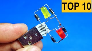
not what was shown in the thumbnail. don't understand why you scraped off the tinning on the wire. it's easier to solder to tinned wire than copper wire.
Interesting choice of battery pack. Never seen that type of battery before - at least not on its own, although I imagine it may be used inside of a rechargeable battery pack (at least in the USA, it's not one you'd buy at a typical store).
Можно бесконечно долго смотреть как течет вода, горит огонь и как работают другие. Смысл ролика в продвижении продукции какой-то организации, торгующей платами. Пайка получается красивая, но 400 градусов !!! Стоит чуть передержать жало на детали, и можно всё испортить. Припой с активным флюсом конечно удобен, сразу залуживает и паяет. Если пайку не промыть спиртом, то это одноразовая конструкция. Через некоторе время все детали отвалятся от коррозии.
Yes bro This is the only issue of the circuit. Later I will share a Schematics where I will show how to solve this issue with one more 10k resistor connecting with the vcc and the + switch
@@Creativecreator Just uses a single ON/OFF/ON toggle switch instead of push buttons. Then you will never be able to short circuit it. Your design is quite dangerous as you can short circuit the 3 li-ion cells directly by pressing both buttons simultaneously and risk the cells exploding and causing a fire or damaging your eyes.
Несколько замечаний: Почему бы не показать схему устройства ? И такой ‘ монтаж ‘ хоть выглядит красиво - но не эргономично и не удобно. ( так для демонстрации работы в школу )
PRetty neat video, leave off the music, and by the way, 3, 18650 batteries give you a rated 11.1VDC, not 12.6. Yeah fully charged they are around 4.2/12.6 but that drops off really quick.
@@darkagelo1 Okay, so who are you claiming are using discharged batteries? Especially since Li-ion automatically shut off before they are "discharged"? And nominal is 3.7VDC ie that is their rated voltage, which would give you 11.1 volts, just as I posted.
@@Rem1061 i dont claim that in this video were used discharged batteries but if you use Li-ion at 3.7 volts yeah you use discharged batteries, an remember one thing this is a LED circuit not a vape build, if you put thos batteries at 4.2 in a vape you are drawing 60W, 100W or even up to 300W this circuit use 5w max with the tiny LEDs so the bateries dont drop that easily
@@darkagelo1 How can you claim a battery that is rated for 3.7vdc is "Discharged" when it is at 3.7VDC? that makes no sense at all. A 18650 battery is supposed to put out 3.7V when it is FULLY charged. They do go over, just like the 12v battery in your car gets up to around 12.5
@@НурланЕмбергенов, вся мощность, что не доходит до светодиодов выделяется на транзисторе. Но, я не пойму что-то как это через кнопку работает? Кнопки ведь разрывают цепь!
30w in 12v so 2.5A max i think but the MOSFET is rated for 50A+ no issue at all. Full cool condition buddy. Otherwise I would showed to attach with the heatsink. BTW if you want to connect 100W led then you will defenately need a heatsink. 😃
@@viermidebutura @viermidebutura I am with you here, the circuit could be quite energy inefficient when the MOSFET is operating in the linear region and heat will be produced as a result. One must be careful when designing with MOSFET. However for a small LED application and the TO220 package with the metal back in this case probably is sufficient enough to dissipate the wasted heat. I wouldn't connect a 30W LED in dim for a long period of time without a heatsink.
Thank you good clear and simplified applications. I want to participate in the 2 push button connection correction. When two are working at the same time, a short circuit will occur in the power supply unit, which may cause burns and losses to batteries with relatively high current, in addition to losing part of the circuit, not all novice amateurs in particular, have sufficient knowledge of this science and the risks of errors , They only apply what is seen and this can be avoided, for example, by adding a two-way plastic slide that passes each time over the SW to make it independent of one another. Sorry - cool, keep going
That's a nice & simple voltage controller. I like your construction methods Thanks for sharing. ... Could be used to make a variable power supply, Motor speed controller, LED driver, etc. .... so what amount of current (maximum) can it handle? Can it handle a couple of amps?
@@Михаил-ц7о2о это сопротивление полностью открытого канала (ключевой режим) - спору нет. Здесь предлагается регулировать яркость уровнем потенциала частично заряженного конденсатора в затворе транзистора, и следовательно - с помощью сопротивления частично открытого канала - линейный режим (я именно о нём и писал). Далее закон Ома - в зависимости от сопротивления приоткрытого канала появляется падение напряжения на транзисторе сток-исток, далее умножаем на протекающий ток - вот и мощность, которая будет греть транзистор. Поэтому не зря правильная схема плавного регулятора выполняется на основе ШИМ-регулятора (широтно-импульсная модуляция). Яркость изменяется за счёт скважности - разности времени состояния полного открытия и полного закрытия транзистора. Полевик работает в ключевом режиме и в принципе не греется. А если нужна простая схема просто включения и выключения в цепи постоянного тока без регулировки - то проще использовать тиристор... :-)
@@АлександрВладимирович-й3ц светодиод 3 Вт. аккумулятор 4.2В - транзистор без радиатора не не сильно греется при пониженной яркости. Для миниатюрного фонарика подойдет. (светодиод на радиаторе).
@@Михаил-ц7о2о Опуская вопрос целесообразности регулировки яркости в миниатюрном фонарике....???... перехожу к главному. Автор использует АКБ банки 18650 напряжением 3,7-4,2 В каждая, и того в сумме 12 В. Это и подтверждается подключением светодиодного модуля (10:50). В таких корпусах распространённые светодиоды 10 - 100 W. В 100 Вт модуле используются 100 кристаллов 1 Вт светодиодов, соединённых в гирлянду по 10 шт, и таких гирлянд в параллель -10. Питание 100 Вт модуля 33 В 3А. При меньшей мощности - кристаллов меньше и поэтому их количество в гирлянде и самих гирлянд разное (бывают кристаллы 0,5 Вт). Могут быть и на 16 В. Автор похоже использует 20W, но не менее 10W модуль с напряжением источника 12 В. Ну а это совершенно другие мощности на разогрев...
Two errors in Design: (1) You don't need a 250v cap, 16V will do since the supply input is only 12V. (2) What would happen if both switches are pressed at the same time?? (This will create a Short Circuit across the 12V supply .. SMOKE ! ! ! ).

![[NEW] Simple Electronics Project](http://i.ytimg.com/vi/Q0egyvceEtQ/mqdefault.jpg)
![[NEW] Simple Electronics Project](/img/tr.png)


![[NEW] Simple Electronics Project](/img/n.gif)
A Bit Long video but I hope you will like it :)
Schematics at the end of the video.
For more Info Visit: bit.ly/34uWV3c
Nice👍 bro.
@Android Solve thank you 😊
You brings always new inovative projects. :)
@@ankurchauhan1966 haha thanks again 😁
@@Creativecreator some people like me already know this project and how this works
If anyone is curious, he is using the capacitor to maitain a voltage level on the gate to put the mosfet into semi conductance mode. The biggest problem with this is it will dissipate a huge amount of heat depending on the load and will probably burn out with larger loads. The charge level will also drain away and will not be "constant", so this is just a basic hack using the near infinite resistance of a mosfet gate.
Thanks for the info . How about a bigger capacitor ??
@@UserUser-ww2nj ,,?
@@UserUser-ww2nj Larger electrolytic caps usually lose charge over time by themselves. And using them won't change linear mode of operation of the mosfet. Meaning it will keep overheating. Note that with the last LED on the video you can't see a transistor. Probably because it is a different one and/or with a big radiator.
You're right, when you say that *...the charge level will also drain away and will not be "constant"* !... But the charge level will be kept longer if you use (instead of a 1 μF / 250 V polyester capacitor) a 4.7 μF / 25 V eletrolytic capacitor. But be careful with its polarity (don't forget it's a polarity-sensitive capacitor) !...
Gracia 👍
The problem is when both keys are pressed.
A short circuit occurs, the keys burn out.
Be sure to add 100 ohms to the row of keys.
First resistor from + to first button.
Second resistor from - to second key.
And there is an other solution for the problem of burning out the keys: instead of using one single 1MΩ (one mega ohm) resistor for both microswitches, you'd better use two 1MΩ (one mega ohm) resistors (one for each switch), both connected to the MOSFET's gate.
Pressing both switches simultaneously creates a short circuit between Vcc to Ground. An alternative is to put an additional limiting resistor (at least 1K) in one of the switches although this would slightly slow down either the capacitor charge or the discharge (depending on which switch is chosen High or Low).
A symmetric response protected circuit could be made with two 1M resistors, each connected to the respective switch and then both to the capacitor.
ua-cam.com/video/RAA42bzYnGk/v-deo.html
ua-cam.com/video/xXmgRCfeMro/v-deo.html
A little tip... When bending the wires on a component, hold the wire with the pliers, and to bend the wire, hold the wire, not the component. This way, you don't put any pressure on the wire entering the component. If you bend the component against the pliers then you risk breaking the connection between the wire and the component.
Hope this helps.
Thank you 😊
I always try to hear from you guy and try to improve.
If you build this, DON'T PUSH BOTH BUTTTONS AT THE SAME TIME. I think you'll short circuit your unprotected Li-Ion cells, and maybe cause a fire.
Better use 2 seperate resistors, one for charging and one for discharging the capacitor, then if both buttons are pressed instead current will run harmlessly through 2 resistors... and you'll even add another feature to "set 50% brightness" when both buttons are held. (Because in this case the capacitor will discharge/charge towards half of the supply voltage.)
Those wire strippers are Top 10 buys over the pandemic. Sometimes I just cut the ends of wires for fun.. I am not ashamed.
i love these videos, simple and practical way to understand basic electronics
I like the thought "what the hell is this guy building", followed aaaaaahs and oooooohs 😁
Very interesting, thank you!
Welcome 😁
I didn't really care what you were making because it's miles above my head. I was just fascinated with HOW you were making it. It gives me hope that, maybe, one day I'll be able to solder two wires together without needing to call the fire department. :) Thank you for the inspiration.
You will buddy.
Just Learn Create and repeat 🙂
"Very helpful video, thanks! I'll try the same approach for another project I'm working on."
Good night friend. congratulations for your work. The circuit does not allow to activate the two switches simultaneously as it would short the source.
As a suggestion it would be better to connect a 1M resistor after each switch and connect them to the MOSFET gate.
Yes 😊
You are right ☺️
Powering a higher power load and using the fet in the linear region, the fet is going to get hot, possibly very hot, you need to add a heatsink to the fet. One other thing, show us what happens when you press both buttons at the same time,,,,,,,,battery, switch, wiring check, one of the three will fail and maybe smoke. Thanks for the schematic.
I like your pre-solder technique, excellent video.
👍🏼
Very nice "freestyle" soldering skills. It's one thing to solder a board together where the parts are more or less captive, it's another thing to align parts in space and get good results.
Very true
Just discovered your channel with this video, As a retired twelve year high school electronics teacher just love your techniques. I could have used this video to teach my students a ton of techniques in assembly and electronics in a few minutes. I started out life in professional video production. Your production values and timing are awesome. This is some of the best tutorial video I have ever seen. Thank you
ua-cam.com/video/RAA42bzYnGk/v-deo.html
In future projects with these small 4-pin push button switches, you might consider leaving TWO connections attached on the rigid wire supports for additional strength. That would provide two separate solder connections instead of just the one on a physical button that gets repeatedly mechanically stressed. It would reduce potential for failure of the switch electrically and mechanically.
These 4-pin push buttons usually allow you to connect two pins together for a single connection#1 and the other 2 pins together for connection#2, which increases button sensing reliability (assuming proper debouncing circutry used for mechanical switch). In this particular case you probably also could connect the switch's 4th pin to the flexible wire, if desired. Again, it adds a bit of physical strength and reliability to an electrical connection that is exposed to mechanical forces.
I doubt homeboy is going to be using this in any appreciable sense.
Everything from your soldering to your end product triggered me on so many levels.
Actually it's not all that bad. It's called "dead bug" construction... And with the exception of the nippy clip joints (yes that is cringe lol), the rest are fine for the construct method.
You can be triggered as you wish, but this guys soldering skills are actually quite good.
@@upravytdi thank you so much 🙂
@@upravytdi i cant imagine how bad your soldering skills are.
Soldering temp is too high. Maybe for removing the component but you shouldn't need 400C for lead-based solder. Even lead-free should be around 200C.
This is also a poor design for dimming as it can cause early failures in LEDs due to inaccuracies between the LEDs as you can see from the LED array (the 30W LED) their forward voltage varies so much that just dimming using current isn't sufficient. The correct way to dim LEDs is via PWM. That said, this circuit would be better suited to an incandescent bulb.
The reason the soldering looks bad is because the initial board for the voltage regulator was dirty, the connections look clean and I don't see any cold solder joints so I see no issue with the later soldering.
A transistor out of an old welding circuit
A 1megaohm resistor and a 250pf telephone socket capacitor button switches LEDs and crocodile clips. And maybe two 9v batteries in series.
I tried this it is working great. I used old SMPS components. Thank you so much for sharing this trick as well as the Schematics.
Glad it helped
ua-cam.com/video/RAA42bzYnGk/v-deo.html
Dobry pomysł. Krokodyl w kurczliwym rękawie
Ja mam rtęciowe oświetlenie biurka na moim kanale, elektronikę również uwielbiam;)
Don't push both button switches at once! You shortcircuit the battery.
I mentioned that to the given link in the description 😁
Two resistors could be used in order not to short circuit.
@@WISELORD Don't even need 2, just one.
At last a tutorial video with soldering that doesn't drive me insane. Great work
Haha thanks 🙂
Схема требует доработки.Если случайно нажать обе кнопки будет короткое замыкание.Между минусовой шиной и кнопкой добавить резистор.
Ok
Диод а не ристор
Great projects for school level children entry level, and to inculcate interest in electronics.
My suggestion as a senior in the field (senior citizen also), instead of digchik, digchik music explain the characteristic function of each component. This would help the child build an analytic thinking and design some thing on his own, rather than spoon feeding.
Wish you explained a little more what you are doing each step so I could learn. The visual part is perfect just needs a little narration.
Check this: getvid.cc/12v-led-dimmer-with-irf3205-mosfet-and-1uf-ac-capacitor/
exactly
I think it’s more fun just watching and then researching what’s going on afterwards.
he just made a changing light from low to high probably one of the easiest things to do. imo
@@xWarPlays everything is easy when you know what you're doing...
Thank you for showing the soldering techniques from start to finish . Many people forget that beginners don’t have this skill set and I know from experience that this can be very frustrating if you don’t know the little tricks that make things stick 😉. Great video
ua-cam.com/video/xXmgRCfeMro/v-deo.html
Хорошо провёл 12 минут, спасибо, залип на просмотре!
Sangat bermanfaat terimakasih ilmunya
Thanks for sharing, but the music makes me want to put a fork in my ear😂
ua-cam.com/video/Kzwpb9TD3wg/v-deo.html
sooo, buttons are for charging and discharging that capacitor that feed the gate, more power to gate more power to drain and brighter leds, if you let it longer without press button for more power leds will go off. correct me if i am wrong :D
sponsor: nextpcb
project: no pcb
Nice circuit! It’s nice to see a simple analog design that doesn’t use a microcontroller or Raspberry Pi...
This is a great project, I just implemented a similar circuit when my wife's cigarette roller stopped working (some machine oil dropped onto the circuit board and fried it). It was being driven with a simple 5v DC motor, but they chose to use a 9v power supply supply (there were no resistors or MOSFETs on the original circuit board, it was just a barrel jack, a push button, and the motor). By implementing this kind of circuit and an LED indicator, it allows her to control how much current is flowing to the motor, and will hopefully help the motor last longer.
What happens if you press both buttons at once? (walks away whistling quietly). I'd put a 10k or so resistor between them to mitigate the result of that.
I really want to know
@@thengspjo4716 Press both at once, you short the battery.
@@ian12262 ok thanks, I was actually going to build it just to push both buttons at the same time
I really like your soldering technique it looks really good
Thank you so much!!
When you soldered the first leg of the capacitor I thought, that isn't a very good joint but then you soldered the other leg and came back to the first to make a good joint. Nice technique!
Thank you. 😄😄
Good job my friend keep it up ❤❤❤❤❤❤
Just realized how mosfet working with simple video, thank you
I spent a whole semester trying to understand this lmao
@@walkerspier7751 lmaoooooo
Great project my friend. Great jobs
Bro... i ran the circut for 2hrs and the full brightness led got dimmed now
It seems like the self discharge rate of this small capacitor is too much
i recommend decreasing the resistor value and increasing capacitor to somthing like 4,700uf
But this is the capacitor which was available to me this time. I tested for 1 hr this circuit this works great.
Check the push buttons buddy even while making the video i have so long head push buttons which I was going to use in this but while testing the circuit. I got the same issue like you.
Thia is because small current was flowing through the push button even after not pressing the switch.
If you know about MOSFETs characteristics then you will find the mosfets gete remains charged after giving voltage to the gate. So, for discharging the gate we have to use a discharge resistor fron gate to gnd.
Now your circuit's led brightness is going low because your switch has some linkage. So it is grounding the gate current.
One major flow of the circuit is that you can not press the 2 buttons same time. Then the circuit will be short-circuited.
This is the main flow.
Hope this helps 🙂
@@Creativecreator Woops... my capacitor was water damaged that was letting ** Very Small ** current to flow and discharge it...
Replaceing the capacitor helped
And i will test this night to see what happnes
Am also creating electronic videos if u like then Subscribe
👍✌️👌
@@Experiment_Club ok so you and @D P Are promoting there channels (fine with me) @The Experiment Club How many subs do you have
Molto belle queste piccole e geniali invenzioni bravo
Friend your work is unbelievable. Congratulations!
A hug from Rio de Janeiro (January River) - Brazil
Thank you so much 😀
3205 transistor is very good. Working. Nice
Brother I watch your video every day💓
Thank you 😊
Oh my God. Such a simple circuit and still useful. Thank you so much
@Raul okay, how are you doing ..?
ua-cam.com/play/PLGcef26PS_0h67KqQExWjM7iPCwdtZs9_.html
@Raul kindly text me on my number 9132865115
Good and wonderful work. I wish you success in your careers. Thank you for this beautiful dimension/
nice video! I don’t think I’ve ever heard of that kind of terminal classification: Middle regulator leg is “drain” LOL
irf 3205 regulator?
components101.com/mosfets/irf3205-pinout-datasheet
@@ashishsaxena4054 I’m just messing around lol
Very slick dimmer circuit, nice job. Never realized it was that simple!
You: How you keeping busy during this lockdown?
Me:
What is happening here? Are you changing the charge of the capacitor?
excellent clean soldering and overall work!
ua-cam.com/video/RAA42bzYnGk/v-deo.html
Cool project! Только в сток-затворе полевика заряд конденсатора бдет со временем снижаться и яркость подключенных LED уплывать, так схема любопытная!
Use 0.1F super capacitor. 0.5 dollars. Capacitor discharge takes days.
Isn't it a bad idea to make a virtual ground for the LEDs?
Ok, this is legit garbage from components to the way you soldered it, but I'm gonna sub. This thing is hilarious and I've never seen something this wrong, but actually working.
You are such a genius bro🙏..
Thank you so much 😀
👏👍✌️
@@thearchetype9829 ua-cam.com/video/bxkCUfSzNv8/v-deo.html
Dear Creativ...please make a video to explain how you decide
1. Which component to use, and
2. Where to place it
Thank you
Simple project, yet very functional... I like it.
Thank you
Push-button increase and decrease of LED intensity with only one MOSFET? That is interesting
EDIT: how long does this circuit hold the last dimming position?
And I suppose the MOSFET acts as a resistor when it lowers the power to the load.
Good idea, thanks....
You are welcome
👍✌️👌
not what was shown in the thumbnail. don't understand why you scraped off the tinning on the wire. it's easier to solder to tinned wire than copper wire.
Over 1.3 million views in just 1 week, amazing dude👏
Interesting choice of battery pack. Never seen that type of battery before - at least not on its own, although I imagine it may be used inside of a rechargeable battery pack (at least in the USA, it's not one you'd buy at a typical store).
And if you want to have nice smoke, press both buttons at the same time. ;) (Just jokeing, don't do this, this shorts out the 12 V)
@Arghadip I would rather add a second 1M Resistor. A Resistor after each switch. The star point then to the Capacitor.
Press two buttons simultaneiusly leads to buttons and wires from battery holder to burn
Wow i love it you are genius bro and the other video I tried it and it was working 😃
Promise guys try it it was working
@janrey roblox I love it , how are you..?
@@Its_JanreyPLAYSROBLOX I I n ben U.K. I
Where is the schematic diagram of that lighting control?
Harika bir filmdi ve harika bir icattı.
Who's the music from?!? Came for the video, stayed for the music!
Stayed for the baby fingers
Lmao
spring gang feat. LaKesha Nugent - You Left Behind
ua-cam.com/video/o2HUEu56ks4/v-deo.html
3 yeas ago but still amazing . Thanks bro 🙏
Без полезный просмотр, проще по схеме собрать, для чего я это смотрел 11 минут?
Можно бесконечно долго смотреть как течет вода, горит огонь и как работают другие.
Смысл ролика в продвижении продукции какой-то организации, торгующей платами.
Пайка получается красивая, но 400 градусов !!! Стоит чуть передержать жало на детали, и можно всё испортить. Припой с активным флюсом конечно удобен, сразу залуживает и паяет. Если пайку не промыть спиртом, то это одноразовая конструкция. Через некоторе время все детали отвалятся от коррозии.
И пайка в стык, когда можно было сделать петлю вокруг проводника непонятна...
You must have forgotten to increase the speed in settiings. I was impatient to see what he was making. A schematic would be helpful.
Hi buddy , you amazing , ❤🙋♂️
Very cool. Also I find this video oddly relaxing hahaha. Good work!
I think this guy owns a electric components shop
Hello there! I like all your videos. If you press two buttons at once, will there be a short circuit?
Yes bro
This is the only issue of the circuit.
Later I will share a Schematics where I will show how to solve this issue with one more 10k resistor connecting with the vcc and the + switch
@@Creativecreator Just uses a single ON/OFF/ON toggle switch instead of push buttons. Then you will never be able to short circuit it. Your design is quite dangerous as you can short circuit the 3 li-ion cells directly by pressing both buttons simultaneously and risk the cells exploding and causing a fire or damaging your eyes.
Несколько замечаний: Почему бы не показать схему устройства ? И такой ‘ монтаж ‘ хоть выглядит красиво - но не эргономично и не удобно. ( так для демонстрации работы в школу )
Forget the resume. You're hired.
Haha Nice one :)
👍✌️👌
Very good regulated power thanks sir
Make 3.7v to 5v boost converter circut
Ya I know you want to make a power bank 😏😏😏
You explaining what you are doing and why beats music everyday of the week
6:48 that double strip 😎
7:57 not ready for that😂
Plus the fet will get hot in its linear region and will need a heatsink for the bigger led
PRetty neat video, leave off the music, and by the way, 3, 18650 batteries give you a rated 11.1VDC, not 12.6. Yeah fully charged they are around 4.2/12.6 but that drops off really quick.
I charged them before using lol 😁
Nominal voltage is 3.6V but if you're simply a dumb if you use discharged batteries
@@darkagelo1 Okay, so who are you claiming are using discharged batteries? Especially since Li-ion automatically shut off before they are "discharged"? And nominal is 3.7VDC ie that is their rated voltage, which would give you 11.1 volts, just as I posted.
@@Rem1061 i dont claim that in this video were used discharged batteries but if you use Li-ion at 3.7 volts yeah you use discharged batteries, an remember one thing this is a LED circuit not a vape build, if you put thos batteries at 4.2 in a vape you are drawing 60W, 100W or even up to 300W this circuit use 5w max with the tiny LEDs so the bateries dont drop that easily
@@darkagelo1 How can you claim a battery that is rated for 3.7vdc is "Discharged" when it is at 3.7VDC? that makes no sense at all. A 18650 battery is supposed to put out 3.7V when it is FULLY charged. They do go over, just like the 12v battery in your car gets up to around 12.5
Simple and effective project. Also give some digital simple project too.thanks a lot.
Транзистор в линейном режиме?
Получи печку в подарок. Только для маломощных светиков.
Как это понять? Типа в линейном режиме он греется?
@@НурланЕмбергенов Транзистор будить греться.
@@НурланЕмбергенов, вся мощность, что не доходит до светодиодов выделяется на транзисторе. Но, я не пойму что-то как это через кнопку работает? Кнопки ведь разрывают цепь!
شكرا لك.هذا ماابحث عنه.بالتوفيق.
That was a cool circuit
Thank you 😊
Yea, realy.
This is the contrary of cool, cause it doesnt use something like pulse width modulation, so the power MOSFET is getting very hot!
Nice project. -but is it worth the components? -no...
Amazing
Thanks
what is your video camera
Спасибо, очень понравилось. подписка :)
hey that will heat up the mosfet quite a lot when you turn on the bigger led on half of the full brightness.
30w in 12v so 2.5A max i think but the MOSFET is rated for 50A+ no issue at all. Full cool condition buddy. Otherwise I would showed to attach with the heatsink.
BTW if you want to connect 100W led then you will defenately need a heatsink.
😃
@@Creativecreator yeah
@@Creativecreator the MOSFET is rated for 50A+ when fully ON not when it operates in the liner region
@@viermidebutura @viermidebutura I am with you here, the circuit could be quite energy inefficient when the MOSFET is operating in the linear region and heat will be produced as a result. One must be careful when designing with MOSFET. However for a small LED application and the TO220 package with the metal back in this case probably is sufficient enough to dissipate the wasted heat. I wouldn't connect a 30W LED in dim for a long period of time without a heatsink.
Thank you good clear and simplified applications. I want to participate in the 2 push button connection correction. When two are working at the same time, a short circuit will occur in the power supply unit, which may cause burns and losses to batteries with relatively high current, in addition to losing part of the circuit, not all novice amateurs in particular, have sufficient knowledge of this science and the risks of errors , They only apply what is seen and this can be avoided, for example, by adding a two-way plastic slide that passes each time over the SW to make it independent of one another. Sorry - cool, keep going
Nice idea i will be adding a next version of the circuit where you can press both switches and there will not be any short circuit.
чувак, тебе тока взорватся за аллаха
That's a nice & simple voltage controller. I like your construction methods Thanks for sharing.
... Could be used to make a variable power supply, Motor speed controller, LED driver, etc.
.... so what amount of current (maximum) can it handle? Can it handle a couple of amps?
Yes it can but I suggest you to use a heatsink for higher amps. As it is a linear circuit.
dang, I Thought you were.making some trash with lights, and you just made a voltage regulator kinda thing out of that ckt well done man.
Means alot 🙂
@@Creativecreator massage therapy
Всё гениальное - просто! Высший бал.
Полевой транзистор в линейном режиме да ещё с мощным светодиодом быстро задымится
@@АлександрВладимирович-й3ц сопротивление канала должно быть 0,008 Ом. - LR7843 меньше падение напряжения сток исток - меньше потерь на нагрев.
@@Михаил-ц7о2о это сопротивление полностью открытого канала (ключевой режим) - спору нет. Здесь предлагается регулировать яркость уровнем потенциала частично заряженного конденсатора в затворе транзистора, и следовательно - с помощью сопротивления частично открытого канала - линейный режим (я именно о нём и писал). Далее закон Ома - в зависимости от сопротивления приоткрытого канала появляется падение напряжения на транзисторе сток-исток, далее умножаем на протекающий ток - вот и мощность, которая будет греть транзистор. Поэтому не зря правильная схема плавного регулятора выполняется на основе ШИМ-регулятора (широтно-импульсная модуляция). Яркость изменяется за счёт скважности - разности времени состояния полного открытия и полного закрытия транзистора. Полевик работает в ключевом режиме и в принципе не греется.
А если нужна простая схема просто включения и выключения в цепи постоянного тока без регулировки - то проще использовать тиристор... :-)
@@АлександрВладимирович-й3ц светодиод 3 Вт. аккумулятор 4.2В - транзистор без радиатора не не сильно греется при пониженной яркости. Для миниатюрного фонарика подойдет. (светодиод на радиаторе).
@@Михаил-ц7о2о Опуская вопрос целесообразности регулировки яркости в миниатюрном фонарике....???... перехожу к главному. Автор использует АКБ банки 18650 напряжением 3,7-4,2 В каждая, и того в сумме 12 В. Это и подтверждается подключением светодиодного модуля (10:50). В таких корпусах распространённые светодиоды 10 - 100 W. В 100 Вт модуле используются 100 кристаллов 1 Вт светодиодов, соединённых в гирлянду по 10 шт, и таких гирлянд в параллель -10. Питание 100 Вт модуля 33 В 3А. При меньшей мощности - кристаллов меньше и поэтому их количество в гирлянде и самих гирлянд разное (бывают кристаллы 0,5 Вт). Могут быть и на 16 В. Автор похоже использует 20W, но не менее 10W модуль с напряжением источника 12 В. Ну а это совершенно другие мощности на разогрев...
Thank you. Also, I enjoyed the music.
👍👍👍👍👍👍
Vai fica TOP nas minhas MINIATURAS
man esqueceu que o cara é do estados unidos
Two errors in Design:
(1) You don't need a 250v cap, 16V will do since the supply input is only 12V.
(2) What would happen if both switches are pressed at the same time?? (This will create a Short Circuit across the 12V supply .. SMOKE ! ! ! ).
Nice I subbed
Creative video, thanks for sharing it :)
Не знал что чтобы отпаять один транзистор, нужно сначала отрезать кусок платы