Hall Effect Sensors

Вставка
- Опубліковано 9 лют 2025
- PCBWay, the best custom PCB prototype service, visit www.pcbway.com... and claim your $10 coupon using the code "ludic" (valid for first 100 clients). Free shipping for PCB Assembly orders may 2 - june 2.
Hall sensors, what are they, hoy they work and how to use them.
Support Ludic Science on Patreon:
/ ludicscience
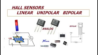
Hall Effect sensors come in two basic types:
1. Threshold (alternatively called digital, or on-off), which produce a constant hall voltage when the field strength reaches a certain amplitude and/or polarity. There are many different threshold device configurations such as latching devices which turn on when a positive field strength reaches the threshold but only turn off under a negative field of the same strength, or devices which turn on when only a positive field reaches a certain threshold and are off otherwise, or devices which turn on when either a positive or negative field reaches the threshold and are off otherwise, etc. Certain devices even have programmable thresholds.
2. Linear, (analog output sensor) which produced a hall voltage proportional to the strength of the magnetic field around it. The orientation of the surrounding magnetic field determines the polarity of the voltage swing. Linear devices are more often used in musical applications, when expressive gestures must be sensed as tiny changes in position.


The simplicity of your setup and the wonderfully clear explanation is always worth the time to absorb. Best explanation of a Hall effect sensor.
Thank you for providing an alternative view, which often explains it better than most others.
Well done, you are a great help to those whom are learning.
Thanks!!!!
Ludic Science
No need to thank me, this also applies to all your work I’ve had the pleasure of viewing.
Please keep doing what you are doing.
@@deangreenhough3479 This was the 1st vid I've watch from LS. Your comment was right on, "alternative view, which explains better that most others", so, I subscribed, thank you.
Images and real life situations worth thousands of words and theories
If the magnet is meant to be directly above the plate of material at 0:48, I believe the Lorentz force will tend to push the electrons in the direction opposite to the one shown (electrons have a negative charge). The magnetic field lines are pointing upwards, while the motion of particles is from right to left.
In fact, this property means that both positive and negative charge carriers would be pushed towards the same side of the material even with the same direction of conventional current, allowing the first demonstration that electrons (negative) were the charge carriers.
Shut up, go and study, what is cause and what is effect then argue.
@LudicScience I think this is correct, is it not? The electrons will move to the opposite direction you have shown in your video. However, the holes do not actually move as holes are just the positive ions in its fixed position. So as the free electrons move to the other side, the original side has less electrons which is why it is positively charged. Please correct me if I am wrong. Thank you
I love this channel! You explain things clearly and give good examples of usecases. Great job!
LS, no doubt the informations you give in the video is highly commendable.
Brilliant explanation, love the practical circuit! Thank you for posting this. I was trying to explain Hall Sensors to my 13 year old.
Your demonstrations are superb in their clarity and your explanations are so well delivered! I really appreciate all of your excellent videos! Thank you for your efforts. You are making a difference!
Very nice ❤️❤️❤️...
One of my favourite channel....
Thank you sir
Best explanation of a Hall effect sensor.
Thank you so much for such a concise explanation. You managed in 6 minutes what my dithering lecturer couldn't manage in over a boring hour. You are a STAR-
As usual Ludic, this is a very clear and helpful video. Thank You.
Very beautifully explained
Great explanation in very simple to understanding manner!
Great video, exactly what I needed to know to rebuild my fan blower a new controller. This consists of 4 coils series wounds with obviously a hall sensor for a magnetic switch 😁
Another great and useful circuit with a very well explained example. I wish more people would see the knowledge you share with the world.
Excellent video. Really shown in a very simple way the hall sensor principles. Thanks a lot!
That was an excellent explanation! I totally get it! Please be careful when pointing to a live circuit (I know yours was off) with a pencil. The graphite center will carry current to the eraser end and can jump to the metal holding the eraser. 💢💥
You probably know this, I just wanted to tell everyone that may read this. Use a non conducting pointer that is all wood or plastic.
You can even make one out of a chopstick! 😃 Be safe, My Friends!
Thanks!
Very informative. Thank you.
Nice circuit &good explanation.
So its kinda a Solid State reed switch, Cool!i've also seen "Analog" version where you can read the strength of the magnet, the stronger, the bigger the current.
You make great videos
thank you very much. That's video is wonderful. Right now I understand this how it works
Very clear expalining
Excellent video. Thanks for sharing!
Your way of presentation hits directly to the brain 💉😸
I will try to implement that in my next class
Very clear explanation. Thank you
thank you sir, simple explanation easy to understand.
Will that output be the same voltage value as the original value that we supplied to the hall sensor?
Excellent information
Very good explanation. Thank you and well done.
Thanks very much, very easy to understand !
You are very amazing , thank you ♥️
Thanks bro electric scooter Technicians very useful this circuit . many many thanks for you
nice video and clear explanation
superb video sir...... thanks for sharing.
Excellent instruction - as usual.
👍
😊
Thanks very much for giving $10
very clear how to use the hall effect as a switch on mains voltages
Thank u so much for this wonderful video
I really understood well
Greatly explained mate! Thanks! what type of Hall sensor are you using in this video pls?
Hello Ludic Science, what are you using the A3144 or the Y3144 ?
Thanks a lot for the knowledge.
Super thanks.
What force you said moves the electrons, deflects them?
I have a question, I notice that the light came on when you put the magnet near the sensor, and only went off when you reversed the magnet... when switched on, how long does the light stay on? Is there a length of time or does it stay on until you expose the sensor to the magnet again (reverse the magnetic field)?
The reason I'm asking is I am trying to design a hall effect rotary encoder for a cnc machine I intend to build.
This encoder would tell the speed, direction, and distance if I can get it working...
I think this transistor is more sophiscicate that basic principle he explained in the beginning of vidio. It has memory effect.
VERY interesting. I think I need to know how my flashlight that works using a magnet in the on/off switch. Light goes on/off by moving the magnet but not switching the poles.
Nicely explained
wow amazing thanks
I want to trigger a 2n3055 from a Hall effect sensor BUT the out put from the Hall Effect sensor is negative but the base of the non transistor needs a positive signal ....Please, anyone how do I get round this problem ?
I'm sorry, I have to ask. What kind of relays and sensors are used on this experiment?
I remember with hub motors for electric bike when you have a brushless motor you have two types. Sensorless and with hall sensor. With hall sensor you apparently can start from a full stop and with sensorless you can't but sensorless is much more energy effective. Not sure about this though?
I´ve heard that sensorless motors are more efficient at high speeds
Saudações LS Science. Saudações a todos. Interessante. Não sabia que era assim que os sensores hall funcionavam. Um pólo magnético desliga e o outro liga e vice- versa. Muito bom. Parabéns. Tudo de bom.
sir u r so great u explained excellently thanks
Love it. Thanks.
i was very confused when you introduced resistors and relays and resistors, no idea how those are meant to work in there.
Loved the video. Very simple and clear explanation.....very well presented. Thanks you! I subbed.
Thanks
una excelente explicacion de los sensores magneticos o hall effect sensor y me parece muy interesante gracias
I'm confused as to why the lamp stays ON or OFF.
Does the hall effect sensor keep the polarisation? or is this happening on the transistor side somehow?
Great video as usual. Thanks. Can I connect a 48v battery to the hall sensor like in the diagram in the video?
I made the same first circuit but when i put the magnet in front of the sensor the led just light up and when i remove the magnet it lights down
How do you make latch?I don't get it.
Good explanation, however you never mention that this is a LATCHING hall effect sensor. There are other types that do not act as a bipolar switch as this circuit. A unipolar Hall Effect switch will close, or output a digital High when a magnetic field is present and then open again when the field is removed. There are also linear output Hall sensors that output a current that's proportional to the magnetic field strength....
Ah. That explains what kind of sensor my flashlight has.
the sensors i bought off of ebay normally have no output and when i approach it with north pole it shorts the output and ground. other sensors i have seen on the internet give nothing or + on the output. every model uses different kind of outputs and i havent seen a "most common one". all hall sensors are the same, the question is what opamp or other current amplification circuit the manufacturer has integrated in the package
Refer to datasheet, pins and specs could be different.
*most probably different. that is my point
very nyc...u did an awesome job.
Is this type of sensor that acts like switch the one present on the throttle of Ebikes?
How is the LED grounded?
Respetuosamente quiero comentarle que pareciera que conecta o desconecta la parte que va al negativo.
Usted sugiere que es como un interruptor entre el positivo y la salida.
Cordial saludo
very interesting thank u
can it detect an AC EMF ?
Naive question: why is it necessary to add the 220 ohm resistor before the BC556
transistor?
GOOD JOB
Very nice sir
as always it was great
I clicked on this vid because this how my instructor taught us in our circuits 1 class.
please tell me the no of hall effect transistor
I remember finding a circuit that changed the frequency of an oscillation based on a magnet moving. Any idea how that could work?
what kind of oscillator?
Ludic Science I never really saw it long enough and it was far enough back that I don't exactly remember
+Ninja, you could change oscillation(if it is a simple LC tank circuit) by moving a core(magnetic, iron, ferrite..etc.) inside the coil, since this changes L, to much higher value, see this experiment with LC meters and ferrite rods.
ua-cam.com/video/_7of69KW-JM/v-deo.html
ua-cam.com/video/nmrNVhUJKfw/v-deo.htmlm48s
and watch this ua-cam.com/video/V9JoygnVr6o/v-deo.html
yours video is esay to understand,keep make something like it
Thank you.
Can you tell me how to detect only the presence of magnetic field(not the polarity) using hall sensor??
For that you need a reed switch
Can it be done without Reed switch??
Anindya Mitra, Get a regular compass, put it at the desired place, so the needle directs to North.
Use 1 LED or laser LED (from cheap laser pointer) and 1 LDR, put one of them above and the other below. So, the needle covers light.
You might wanna put the LDR inside a small cut of a straw and paint it black so it reaches just below the needle.
make a hole in the lower part of the needle to pass light.
Bring a magnet close to the needle, it moves towards that magnet, then light passes from LED/laser to LDR.
You can make several holes (6,9..etc.) below the compass case then cover them with black tape and only use the needed one. and same for compass case cover, make several holes(if needed, maybe it is transparent so you do not have to make holes).
You get the idea, then carry on from there.
i.stack.imgur.com/tpnL9.jpg
You could use an LED instead of LDR to detect light.
ua-cam.com/video/laDC2LtL4xE/v-deo.html
makezine.com/projects/make-36-boards/how-to-use-leds-to-detect-light
Remember, cover the sides of the light detector/receiver(LDR, LED...etc.) with a small straw same size and black tape, or paint the straw black with marker/black pen/paint...etc.
LDR provide change in resistance while LED provides voltage.
White LED could be best as receiver of light.
just use 2 sensors off of ebay/ electronics store and physically put them back to back, or get a sensor from some electronic device like floppy drive (the rpm and rotor position detection sensor) and hook it to an opamp
John Scarce,thanks
What is Sensor model
put the magnet on a motor and spin it by the sensor!
Trasister name please
Super sir
Nice
awesome
We want show your face in the next videos
😎
Good
Why Hall Sensors Are damaged sir
What is the sensor code ?
Us1881kua
If your school got Arduino stuff, then use the Hall Effect Sensor
duckduckgo.com/?q=Arduino+Hall+Effect+Sensor&iar=images&iax=images&ia=images
You're Top
Sir trasister name
Saoot and noort😂😅like nice video
Muito bom!
Why 9 people disliked this?
Because they are ass
Boa explicação...
Obrigado
Do any of these videos talk in english?
fun
Now you can use your magnetic implants to interact with shit.
Bad English pronunciation..don't even understand 👎
very nyc...u did an awesome job.